Challenge

Week-6 Challenge: EV Drivetrain

1)POWER CONVERTERS USED IN HEV & EV VECHICLES

  1. By using power converter we can varry the output with minimum losses and high stability with better control.
  2. Without the help of power converters the HEV&EV cannot the operated.
  3. With the help of power converts are used to
    • Stabilizes the input power (AC to AC converters).
    • Charging the battery from the power source (AC to DC converters).
    • And controlling the other controllers in case of both step up and step down(DC to DC converters).
    • Powering the induction motor (DC to AC convertres).

Generally used power converters are listed below

AC-AC CONVERTERS

  • These converters are used for stabilizing the input AC supply (from the grid) in the case of controlling/varrying both voltage and frequency of the supply before entering to the rectifing unit.
  • This is done by the help of inverters,auto transformers etc.
  • By the help of Auto transformer we can only varry/control the voltage we cannot varry/control the frequency of the supply.
  • By the help of inverter we can control/varry both the frequency and the voltage of the supply.
  • This fig represents the basic circuit diagram of the inverter.

AC-DC CONVERTERS

  • These converter are used to converting AC-DC source for charging the battery and to operate the other control units which are present in the vechicle like speakers,dashboard and othe control unit like battery management system,Motor speed controller etc.
  • These operation is done by the help of rectification unit.
  • In this we can control the output voltage & current.
  • It consists of both controlled (using diodes) and uncontrolled (using thyrist) converters
  • There are different type of converters used are
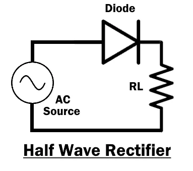
    • Half wave rectifier
      • In half-wave rectification of a single-phase supply, either the positive or negative half of the AC wave is passed, while the other half is blocked.
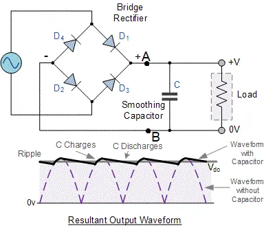
    • Full wave rectifier
      • A full-wave rectifier converts the whole of the input waveform (AC supply) to one of constant polarity (positive or negative) at its output.

DC-DC CONVERTERS

  • These converter plays an vital role in HEV and EV vechicle.
  • These converters are also known as SMPS (switched mode power supply).
  • By the help of these converters we can varry the output voltage in both step up and step down .
  • Here if the output voltage is stepped up the output current is decreased and vise versa.
  • The different types are
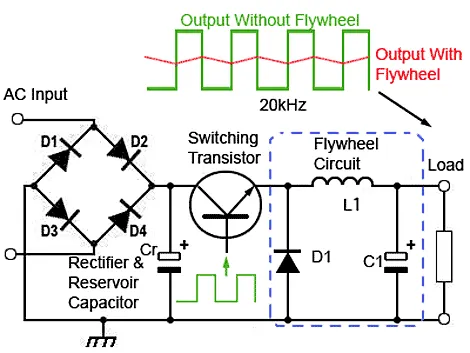
    • Buck converter
      • This converter will step down the output voltage by varrying the duty cycle ratio.
      • Here the 'OFF' period is long comparing to 'ON' period .
      • The output voltage is lower than input voltage (Vin > Vout).
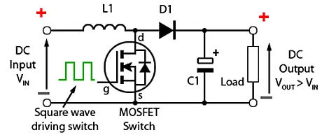
    • Boost converter
      • This converter will step up the output voltage by varrying the duty cycle ratio.
      • Here the 'ON' period is long comparing to 'OFF' period.
      • The output voltage is higher than input voltage (Vin < Vout).
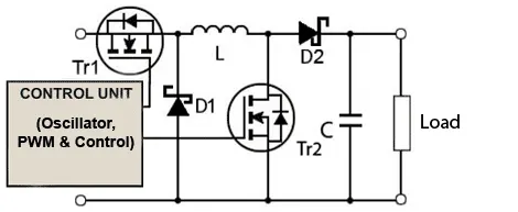
    • Buck-Boost converter
      • It is a combination of both buck and boost conveter.
      • It consists of two transistors T1 & T2 .
      • It works on both DC and AC supply as input.
      • It can produce output voltage in terms of
        • Same as the input voltage (Vin = Vout).
        • Lower than input voltage (Vin > Vout).
        • Higher than input voltage (Vin < Vout).

DC-AC CONVERTERS

  • This is also known as inverter.
  • The inverter is an electronic device used to convert Direct Current (DC) into Alternating current(AC). The Alternating Current is a current that consistently changes its magnitude with respect to time.
  • In EV the inverters are used for powering the induction motor.

2)TO FIND THE STAEDY STATE SPEED IF DUTY CYCLE IS 70%

Given:

Va= 72 V

Ia = 400 A

Ra = 0.5 Ω

Kφ = 0.7

Fc= 400 Hz

D = 70% = 0.7

Tv = 24.7+(0.0051)w2 -------------->①

Solution:

Vavg = Va * D = 72 * 0.7

Vavg = 50.4 V

The average voltage is 50.4 V

W.K.T

T = ((V* Kφ)/ Ra) - (( w* Kφ2)/ Ra)

T = ((50.4 * 0.7) / 0.5) – (w * 0.72) / 0.5)

T = 70.56 – (0.98) w ---------->②

Comparing equ ① & ②

24.7+(0.0051)w2 = 70.56 – (0.98) w

(0.0051)w2 + (0.98) w - 45.86 = 0

This equation represents the quadratic equation

w = -b ± 0√(b^2-4a*c)/(2*a)

w = - 0.98±√((0.98)^2-(4* 0.0051*(-45.86)))/((2*0.0051))

w =(- 0.98 ± 1.377)/0.0102

From solving the above equation, we got

W = 38.9149 rad/sec and W = -231.07184 rad/sec

By considering the forward direction of the motor we consider only the positive steady state speed of the motor by we neglect the negative value

W = 38.9149 rad/sec

3) TO DEVELOP A MATHEMATICAL MODEL OF THE DC MACHINE FOR THE GIVEN EQUATION

GIVEN

ω">ω= V/Kϕ">ϕ -Ra/Kϕ">ϕ^2 .T

MODEL
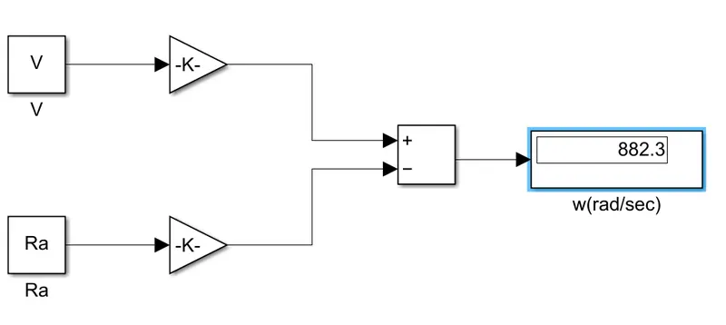
This is the mathematical model for the given equatio n

Where the values of voltage , armature resistance ,motor konstant are feeded into the workspace

4)INDUCTION VS DC BRUSHLESS MOTORS BY WALLY RIPPEL,TESLA

  • From the author perspective he compares the Induction and Brushless motor over the time period .
  • There is no perticular winner between Induction Vs DC brushless Dc motor because each having its loyal proponents and religious detractors.
  • COMBUSTION ENGINE
    • He starts with the gas powered engine vechicles , Those engines are not alike in all vechicle.
    • According to the performance and price the vechicle those engine are selected .
    • And there is no best engine (having low effienciey).
  • ELECTRIC MACHINE
    • In his young period there is only lead acid batteries,lead acid batteries.
    • Nowadays Lead has been replaced by lithium and DC by either DC brushless or induction.
    • After the inverter modules are developed the brushless DC motor and Induction motor become used in EV ,Each will have its loyal proponents and religious detractors.
  • A Closer Look
INDUCTION MOTOR DC BRUSHLESS MOTOR RESULT
CONSTRUCTION
  • It has no permant magnent in rotor
  • It has just stacked steel laminations.
  • It has three sets of “distributed windings” that are inserted within the stator core.
  • The rotor consists of permanent magnet.
  • The stator consists of a core made up of thin, stacked laminations.
  • It has three sets of “distributed windings” that are inserted within the stator core.
  • The stators for the 3-phase induction motor and the DC brushless motor are virtually identical.
  • The essential difference between the two machines is with the rotor.
WORKING
  • The magnetic field enters the stator core and interacts with currents flowing within the windings to produce a torque interaction between the rotor and stator.
  • As the rotor rotates, it is necessary that the magnitude and polarity of the stator currents be continuously varied – and in just the right way - such that the torque remains constant
  • And the conversion of electrical to mechanical energy is optimally efficient.
  • The device that provides this current control is called an inverter.
  • Currents flowing in the stator windings produce a rotating magnetic field that enters the rotor.
  • In turn, the frequency of this magnetic field as “seen” by the rotor is equal to the difference between the applied electrical frequency and the rotational “frequency” of the rotor itself.
  • An induced voltage exists across the shorted structure that is proportionate to this speed difference between the rotor and electrical frequency.
  • Finally, these currents interact with the original magnetic field to produce forces – a component of which is the desired rotor torque.
  • Without inverter, brushless motors are useless motors.
  • No inverter is needed for 3-phase induction motor.
LIMITATIONS
  • Induction machines are more difficult to control.
  • The control laws are more complex and difficult to understand.
  • Achieving stability over the entire torque-speed range and over temperature is more difficult with induction than with DC brushless.
  • They cannot operate from DC; AC is a must.
  • Shaft speed is proportionate to line frequency.
  • Hence, when used with utility power, they are constant speed machines.
  • Finally, when operated from utility power, they have limited starting torque and somewhat limited running peak torque capabilities.
  • Power factor for the induction drive is about 85 percent.
  • DC brushless drives require an absolute position sensor, while induction drives require only a speed sensor; these differences are relatively small.
  • Unfortunately, there is no easy way of changing B with permanent magnets.
  • Permanent magnets are expensive – something like $50 per kilogram. Permanent magnet (PM) rotors are also difficult to handle due to very large forces that come into play when anything ferromagnetic gets close to them.
  • With DC brushless, as machine size grows, the magnetic losses increase proportionately and part load efficiency drops.
  • Induction motor control is complex comparing to DC brushless motor.
  • In BLDC motor we cannot change the B because of the presence of permanent magnet.
  • Induction motor cannot operate at unity power factor.
  • In BLDC motor the size increase the magnetic losses also increases.
ADVANTAGE
  • Induction motors will likely retain a cost advantage over PM machines.
  • Also, due to the field weakening capabilities of induction machines, inverter ratings and costs appear to be lower, especially for high performance drives.
  • Since spinning induction machines produce little or no voltage when de-excited, they are easier to protect.
  • Induction machines have no magnets and B fields are “adjustable,” since B is proportionate to V/f (voltage to frequency).
  • This means that at light loads the inverter can reduce voltage such that magnetic losses are reduced and efficiency is maximized.
  • Thus, the induction machine when operated with a smart inverter has an advantage over a DC brushless machine – magnetic and conduction losses can be traded such that efficiency is optimized.
  • With induction, as machine size grows, losses do not necessarily grow.
  • Induction drives may be the favored approach where high-performance is desired
  • One of the main differences is that much less rotor heat is generated with the DC brushless drive.
  • Rotor cooling is easier and peak point efficiency is generally higher for this drive.
  • The DC brushless drive can also operate at unity power factor, whereas the best
  • This means that the peak point energy efficiency for a DC brushless drive will typically be a few percentage points higher than for an induction drive.
  • In an ideal brushless drive, the strength of the magnetic field produced by the permanent magnets would be adjustable.
  • When maximum torque is required, especially at low speeds, the magnetic field strength (B) should be maximum – so that inverter and motor currents are maintained at their lowest possible values.
  • This minimizes the I² R losses and thereby optimizes efficiency.
  • By the help of closed loop smart inverter we can varry the B where B is proportionate to V/f .
  • BLDC motor cooling is easily done comparing to Induction motor.
  • BLDC motor has high effiency comparing to Induction motor.
  • For the case of higher perpormance induction motor is best.
  • In case of effiency drive BLDC can be choosed.
CONCLUSION
  • Induction drives will likely maintain dominance for the high-performance pure electrics.
  • DC brushless drives will likely continue to dominate in the hybrid and coming plug-in hybrid markets
  • We will see that induction and DC brushless live and work side by side during the coming golden era of hybrid and electric vehicles.
  • There is still no winner
Your portfolio, next

Ship work like this
in your own course.

Talk to a career counsellor

Free 20-minute call. We'll map the right course to where you want to work.

By submitting you agree to our Terms and Privacy Policy.

Talk to a career counsellor

Free 20-minute call. We'll map the right course to where you want to work.

By submitting you agree to our Terms and Privacy Policy.