Week-6 Challenge: EV Drivetrain
1. AIM: Explore A EV Drivetrain Questions-Answers.
2 .OBJECTCIVES OF THE PROJECT:
Give the answer to the below questions to complete the challenge.
- Which types of power converter circuits are employed in electric and hybrid electric vehicles?
- An Electric Vehicle's powertrain with 72V battery pack is shown in the diagram below. The duty ratio for acceleration operation is 'd1' and for the braking operation the duty ratio is 'd2'.
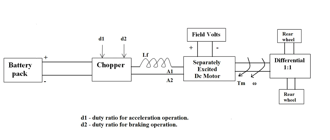
The other parameters of the electric vehicle is given below,
Motor and Controller Parameters:
Rated Armature voltage= 72 V
Rated armature current= 400 A
Ra= 0.5Ω, KΦ= 0.7 Volt second
Chopper Switching frequency= 400 Hz
The vehicle speed-torque characteristics are given by the below equation

What is EV steady state speed if the duty cycle is 70%?
C. Develop a mathematical model of a DC Motor for the below equation using Simulink.
`omega = frac{V_t}{kphi} - frac{Ra}{kphi^2}*T`
D. Refer to the blog on below topic:
Induction Versus DC brushless motors by Wally Rippel, Tesla
Explain briefly about the author's perspective.
3.GOVERNING EQUATIONS IF ANY:
- DC motor equation : `omega_m = frac{V_t}{kphi} - frac{R_a}{kphi^2}*T_m`
4. BODY OF THE CONTENT:
_____Answers of the Questions:
_____Ans. A:
Power electronics is the application of electronics to the control and conversion of electric power. The power semiconductor devices that constitute the power converter exhibit switching characteristics to shape the input power of one form to an output power of some other form. Power Electronics is a field which combines Power (electric power), Electronics and Control systems. Power engineering deals with the static and rotating power equipment for the generation, transmission and distribution of electric power. Electronics deals with the study of solid state semiconductor power devices and circuits for Power conversion to meet the desired control objectives (to control the output voltage and output power). Power Electronics refers to the process of controlling the flow of current and voltage and converting it to a form that is suitable for user loads. The most desirable power electronic system is one whose efficiency and reliability is 100%.
Take a look at the following block diagram. It shows the components of a Power Electronic system and how they are interlinked.
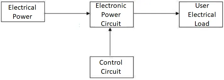
A power electronic system converts electrical energy from one form to another and ensures the following is achieved −
- Maximum efficiency
- Maximum reliability
- Maximum availability
- Minimum cost
- Least weight
- Small size
Applications of Power Electronics are mainly classified into two types − Static Applications and Drive Applications.
Static Applications: This utilizes moving and/or rotating mechanical parts such as welding, heating, cooling, and electroplating and DC power.
Drive Applications: Drive applications have rotating parts such as motors. (including compressors, pumps, conveyer belts and air conditioning systems)
In other area also,
Commercial applications: Heating Systems Ventilating, Air Conditioners, Central Refrigeration, Lighting, Computers and Office equipments, Uninterruptible Power Supplies (UPS), Elevators, and Emergency Lamps
Domestic applications: Cooking Equipments, Lighting, Heating, Air Conditioners, Refrigerators & Freezers, Personal Computers, Entertainment Equipments, UPS
Industrial applications: Pumps, compressors, blowers and fans Machine tools, arc furnaces, induction furnaces, lighting control circuits, industrial lasers, induction heating, welding equipments
Aerospace applications: Space shuttle power supply systems, satellite power systems, aircraft power systems.
Telecommunications: Battery chargers, power supplies (DC and UPS), mobile cell phone battery chargers
Transportation: Traction control of electric vehicles, battery chargers for electric vehicles, electric locomotives, street cars, trolley buses, automobile electronics including engine controls.
Utility systems: High voltage DC transmission (HVDC), static VAR compensation (SVC), Alternative energy sources (wind, photovoltaic), fuel cells, energy storage systems, induced draft fans and boiler feed water pumps
The classification of power converters & brief Introduction that are mostly/sometimes use in EVs as follows:
- AC to DC Converters (Rectifiers)
- DC to AC Converters (Inverters)
- AC to AC Converters (cycloconverter or a matrix converter)
- DC to DC Converters (chopper converter or a switch-mode converter)
1. AC to DC Converters (Rectifiers)
The process of electrical rectification is where current from an ac supply is converted to an unidirectional form before being supplied to a load. The ac supply current remains bidirectional, while the load current is unidirectional.
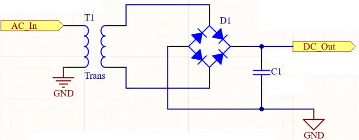
AC to DC Converters (Rectifiers) Block Diagram
2. DC to AC Converters (Inverters)
The process of transferring power from a direct current (dc) supply to an Alternating current (ac) supply is called a process of inversion and the necessary form of converter is usually known as an inverter The operation takes place by the controlled switching of the semiconductor. switching devices. Can see it's basic principle diagram below.
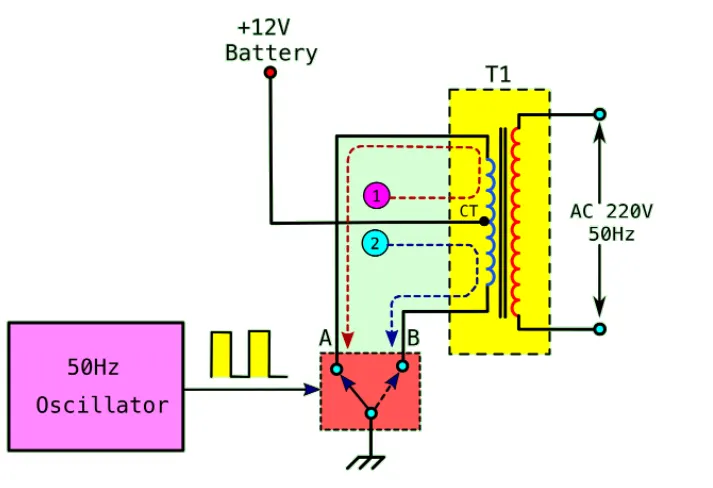
Inverter basic principle diagram
3. AC to AC Converters (cycloconverter or a matrix converter)
A cycloconverter is a static frequency changer that converts an ac supply of fixed input frequency to an ac output of adjustable but lower frequency. The converter consists of an array of back-to-back or inverse-parallel connected switches, usually silicon controlled rectifiers (SCRs). By the controlled opening and closing of the switches it is possible to fabricate output voltage waveforms having a fundamental component of the desired output frequency.
4. DC to DC Converters (chopper converter or a switch-mode converter)
DC–DC converters are used to convert an unregulated dc input to a regulated dc output at a required voltage level. They achieve the voltage regulation by varying the on–off or time duty ratio of the switching element.
_____Ans. B:
From the DC motor equation : `omega_m = frac{V_t}{kphi} - frac{R_a}{kphi^2}*T_m ........1`
`:. omega_m = frac{V_t*kphi - R_a*T_m}{kphi^2}`
`:. T_m = frac{kphi(V_t - omega_m * kphi)}{R_a}`
as per the Motor and Controller Parameters:
`V_t = `Rated Armature voltage= 72 V
`I_t = ` Rated armature current= 400 A
`R_a = `0.5 Ω
`kphi = `0.7 Volt second
Chopper Switching frequency= 400 Hz
duty cycle = 70% = 0.7
` T_v = 24.7 + (0.0051)*omega^2 ...............2`
Now, putting all parameters in equation (1),
`:. T_m = frac{0.7(50.4-omega_m*0.7)}{0.5}`
`:. T_m = 70.56 - 0.98 omega_m ...................3`
at the steady state speed, matching each other, So from eq (2) (3),
`70.56 - 0.98 omega_m = 24.7 + (0.0051)*omega^2`
`:. 0.0051 omega^2 + 0.98 omega - 45.86 = 0` `(because omega = omega_m)`
by solving quadratic equation,
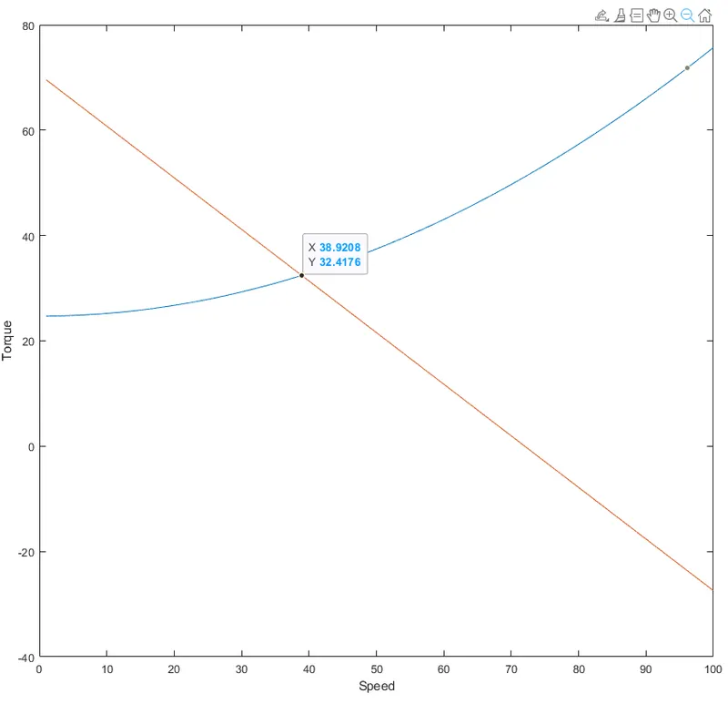
Getting, `omega = 39.02 (rad)/sec` .........4
So, EV speed as duty cycle 70% is 39.02 (rad/sec).
In below graph we can see how, motor speed vs torque & vehicle speed vs torque are intersect at .steady state point'.
_____Ans. C: Develop A mathematical model of a DC Motor for the `omega = frac{V_t}{kphi} - frac{Ra}{kphi^2}*T` equation using Simulink as below.
Assuming Input parameter as below:
`V_t` = 72 (V) Voltage terminal
`kphi` = 0.7 motor constant
`R_a` = 0.5 (ohm) Armature resistance
`T` = increment 1 to 100 (N.m) Torque
`omega` = ___ (RPM)
#MATLAB CODE FOR VARIABLES
%% Variables of mathematical model of DC motor


close all
clc

V_t = 72; % Terminal voltage or Battery voltage (V)
kphi = 0.7; % motor constant
R_a = 0.5; % Armature resistance (ohm)
T = linspace(1,100,100);  % Torque (N.m)

% w_m = (V_t/kphi) - ((R_a/(kphi^2))*T); equation of mathematical model for DC motor
% plot(T,w_m)
#BLOCK ARRANGEMENTS IN SIMULINK
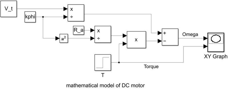
In the above block we can see for some constant values (V_t, kphi, R_a) 'constant block used And for T that value increases with respect to time 1 to 100 'step block' used. To plot in one graph 'XY graph block used'. we can see output as below. where X-axis (Torque), Y-axis(Speed).
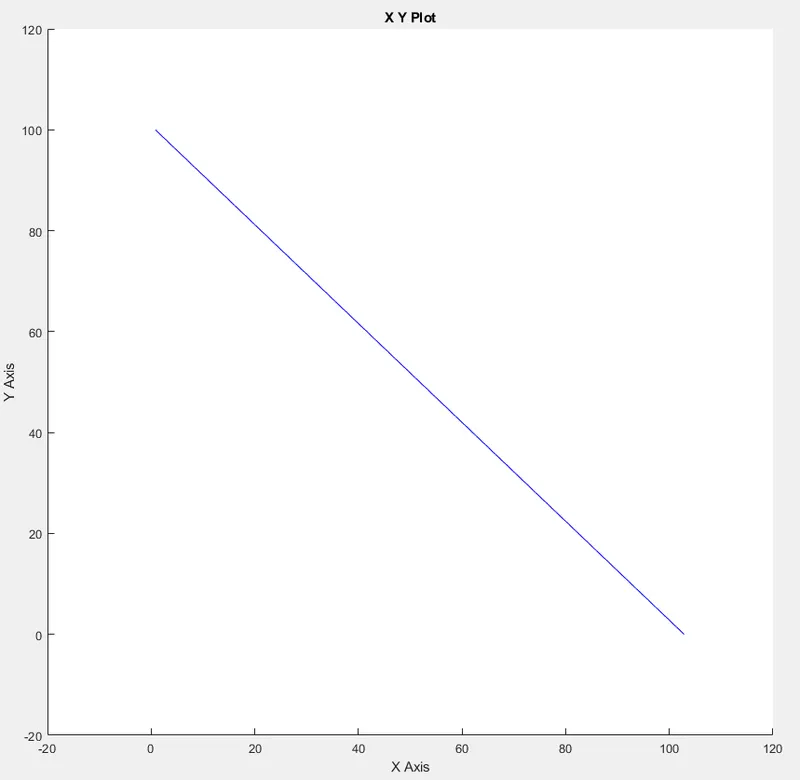
Torque vs Speed
_____Ans. D: Brief about Wally Rippel’s perspective for the blog " Induction Versus DC brushless motors".
In Blog Wally Rippel says "One Size Dose Not Fit All", as engines have many types for their uses and requirements. Not one engine fits for all. The same thing applies in Hybrid and Electric vehicles. Here the engine is replaced with a motor or combine. Then he explains the difference between DC brushless & Induction motors that are mostly used in vehicles. He also explains which is best in which area, how much it costs, what's initial cost, maintenance cost, performance etc. At the end of the blog he written its conclusion.
Finally, after reading the whole blog, the perspective of the blog as per author is, trying to explain how fast the technology is changing in the field of HEVs-EVs. How the DC brushless & Induction motor are trying to dominate in the market. By explaining its characteristics, the motor is trying to say which is bestest. But Still he has No decision on which will be the first. And lastly by asking questions to he increasing curiosity of readers about EVs and saying the vast possibility in the coming golden era of HEVs.