Week-6 Challenge: EV Drivetrain
WEEK – 6
EV POWERTRAIN
Questions
- Which types of power converter circuits are employed in electric and hybrid electric vehicle?
Answer:
POWER CONVERTER:
A power converter is an electrical or electro mechanical device for converting electrical energy.
A power converter can convert alternating current (AC) into direct current (DC) and vice versa. Change the voltage or frequency of the current or do some combination of these.
TYPES OF POWER CONVERTERS:
- AC to DC – Rectifier
- DC to AC – Inverter
- DC to DC – Chopper
- AC to AC – Cyclo converter
Power converter with electric and hybrid electric vehicle employed are,
There 3 types of power converters used in hybrid and electric vehicle. AC to DC, DC to AC and DC to DC. In AC to DC is used to the EV charging, DC to AC is Used to EV motor drive and DC to DC is used for Voltage Step up or Step down the purpose.
-
An Electric Vehicle's powertrain with 72V battery pack in shown in the diagram below. The duty ratio for acceleration operation is 'd1' and for the braking operation the duty ratio is 'd2'.
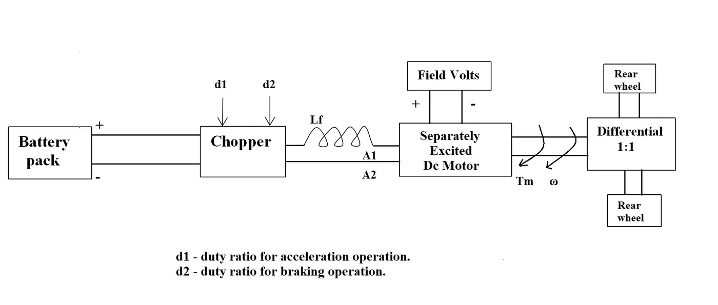
The other parameters of the electric vehicle is given below,
Motor and Controller Parameters:
Rated Armature voltage= 72 V
Rated armature current= 400 A
Ra= 0.5Ω, KΦ= 0.7 Volt second
Chopper Switching frequency= 400 Hz
The vehicle speed-torque characteristics are given by the below equation

What is EV steady state speed if duty cycle is 70%?
Given data:
Rated Armature voltage Va = 72 V
Rated armature current Ia = 400 A
Ra = 0.5Ω,
KΦ = 0.7 Volt second
Chopper Switching frequency Fc = 400 Hz
duty cycle = 70%
Find:
Steady state speed = ?
Formula used:
w = V/KΦ - Ra/KΦ2 .T
V = D * Vin
Solutions:
Motor speed - torque equations,
w = V/KΦ - Ra/KΦ2 .T --------------------------------------------------------------------(1)
V = D*Vin
= 0.7 * 72
V = 50.4volt
Subsitute the 'V' value in equation 1
w = (50.4/0.7) - (0.5/0.72) * T
w = 72 - 1.02T
1.02T = 72 - w
T = 72 - w / 1.02
T = 70.588 - 0.98w ----------------------------------------------------------------------(2)
In steady state speed,
T = Tv
70.588 - 0.98w = 24.7 + 0.0051w2
0.0051w2 + 0.98w - 45.88 = 0 -------------------------------------------------------(3)
in above equation solve the quadratic function,
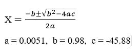
x = 38.92 , x = -231.07
so, the w value is 38.92 rad/sec
Subsitute the w value in equattion 2,
T = 70.588 - 0.98w
T = 70.588 - 0.98(38.92)
T = 32.4 N.m
Result :
Steady state speed is 38.92 rad/sec
- Develop a Mathematical model of a DC motor for the below equation using Simulink.
w = V/KΦ - Ra/KΦ2 .T
SIMULINK MODEL:
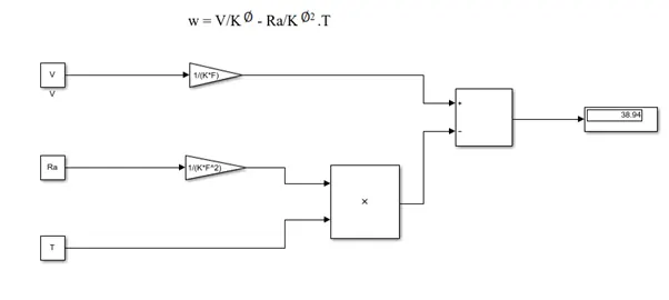
Script Model:
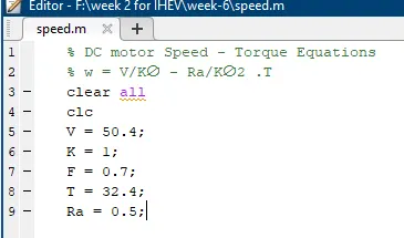
- Induction versus DC brushless motor:
Brushless Motor:
A brushless DC motor (also known as a BLDC motor or BL motor) is an electronically commuted DC motor which does not have brushes. The controller provides pulses of current to the motor windings which control the speed and torque of the synchronous motor. These types of motors are highly efficient in producing a large amount of torque over a vast speed range. In brushless motors, permanent magnets rotate around a fixed armature and overcome the problem of connecting current to the armature. Commutation with electronics has a large scope of capabilities and flexibility. They are known for smooth operation and holding torque when stationary.
Brushless DC motor has only two basic parts: rotor and the stator. The rotor is the rotating part and has rotor magnets whereas stator is the stationary part and contains stator windings. In BLDC permanent magnets are attached in the rotor and move the electromagnets to the stator. The high power transistors are used to activate electromagnets for the shaft turns. The controller performs power distribution by using a solid-state circuit.
INDUCTION MOTOR:
An induction motor (also known as an asynchronous motor) is a commonly used AC electric motor. In an induction motor, the electric current in the rotor needed to produce torque is obtained via electromagnetic induction from the rotating magnetic field of the stator winding. The rotor of an induction motor can be a squirrel cage rotor or wound type rotor.
We need to give double excitation to make a DC motor to rotate. In the DC motor, we give one supply to the stator and another to the rotor through brush arrangement. But in induction motor, we give only one supply, so it is interesting to know how an induction motor works. It is simple, from the name itself we can understand that here, the induction process is involved. When we give the supply to the stator winding, a magnetic flux gets produced in the stator due to the flow of current in the coil. The rotor winding is so arranged that each coil becomes short-circuited. The flux from the stator cuts the short-circuited coil in the rotor. As the rotor coils are short-circuited, according to Faraday’s law of electromagnetic induction, the current will start flowing through the coil of the rotor. When the current through the rotor coils flows, another flux gets generated in the rotor.
Now there are two fluxes, one is stator flux, and another is rotor flux. The rotor flux will be lagging with respect to the stator flux. Because of that, the rotor will feel a torque which will make the rotor to rotate in the direction of the rotating magnetic field. This is the working principle of both single and three-phase induction motors.
Author’s Perspective
- Wally Ripple is joining Tesla Motors, he was engineer at Aerovironment.
- He helped develop the EV1 for General Motors and also worked for the Jet propulsion laboratory on electric vehicle battery research and other projects in 1968.
- He as a under graduate student in Caltech. He built an electric car and won the great transcontinental electric car race against MIT.
- Brushless machines, the rotor includes two or more permanent magnets that generate a DC magnetic field. In turn, this magnetic field enters the stator core (a core made up of thin, stacked laminations) and interacts with currents flowing within the windings to produce a torque interaction between the rotor and stator.
- As the rotor rotates, it is necessary that the magnitude and polarity of the stator currents be continuously varied and in just the right way such that the torque remains constant and the conversion of electrical to mechanical energy is optimally efficient.
- The device that provides this current control is called an inverter. Without it, brushless motors are useless motors.
- Let’s move on to induction motor drives. A forerunner of the 3-phase inductionmotor was invented by Nikola Tesla sometime before 1889. Curiously, the stators for the 3-phase induction motor and the DC brushless motor are virtually identical. Both have three sets of “distributed windings” that are inserted within the stator core. The essential difference between the two machines is with the rotor.
- Unlike the DC brushless rotor, the induction rotor has no magnets just stacked steel laminations with buried peripheral conductors that form a “shorted structure.”
- Currents flowing in the stator windings produce a rotating magnetic field that enters the rotor. In turn, the frequency of this magnetic field as “seen” by the rotor is equal to the difference between the applied electrical frequency and the rotational “frequency” of the rotor itself.
- Accordingly, an induced voltage exists across the shorted structure that is proportionate to this speed difference between the rotor and electrical frequency.
- In response to this voltage, currents are produced within the rotor conductors that are approximately proportionate to the voltage, hence the speed difference.
- Finally, these currents interact with the original magnetic field to produce forces a component of which is the desired rotor torque.
Difference between Induction and Brushless:
|
Induction Motor |
Brushless Motor |
|
No inverter needed |
Inverter needed for phase maintained. |
|
Rotor has No magnet |
Two or more magnets included in rotor. |
|
When a 3-phase induction motor is connected to utility type 3-phase power, torque is produced at the outset |
Brushless DC motor produces no starting torque when directly connected to fixed frequency utility power. |
|
Three phase modulating inverter used. |
Three phase modulating inverter used. |
|
induction drives require only a speed sensor |
DC brushless drives require an absolute position sensor. |
|
Rotor cooling is easier and peak point efficiency is generally higher for this drive. |
Much less rotor heat is generated with the DC brushless drive. |
|
The best power factor for the induction drive is about 85 percent. |
The DC brushless drive can also operate at unity power factor. |
|
Induction, as machine size grows, losses do not necessarily grow. |
DC brushless as machine size grows, the magnetic losses increase proportionately and part load efficiency drops. |
|
Induction motors will likely retain a cost advantage over PM machines |
Permanent magnets are expensive Something like $50 per kilogram. |
Conclusion:
- The Brushless drives will likely continue to dominate in the hybrid and coming plug in hybrid markets.
- The induction drives will likely maintain dominance for the high performance pure electrics.
- Both drives hardware is common that mean live and work side by side during the coming hybrid and electric vehicles.