Week -2
Week 2 Challenges
QUESTIONS
1.Make a Simulink model of doorbell using solenoid blocks with the following details:
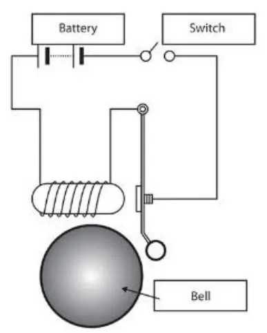
in the above arrangement, when the switch is closed the electromagnet receives electrical power from the battery and pulls the metal arm to hit the bell producing sound.
Create a situation where the switch is closed for 2seconds and then relaxed. Observe the physical movement of the plunger.
- Use a thermistor to sense the temperature of a heater & turn on or turn off the fan as per below conditions:
Temperature source: 200C from 0 to 10sec,270C from 10 to 30sec,230C from 30 to 50sec.
Fan conditions: ON if the temperature above 250C,off otherwise
ANSWERS
1.DOORBELL
AIM: To Make a Simulink model of doorbell using solenoid blocks.
Requiremets:
Solenoid
Battery
Switch
Ideal translational motion sensor
Pulse generator
Simulink -PS converter
PS-simulink converter
Electrical reference
Mechanical translational reference
Solver configuration
scope
OBJECTIVE:
when the switch is closed the electromagnet receives electrical power from the battery and pulls the metal arm to hit the bell producing sound.
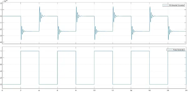
Create a situation where the switch is closed for 2seconds and then relaxed. Observe the physical movement of the plunger
How it is work?
Assume the switch is closed the solenoid is an electromagnet with wire winding small metal piston inside it. When electric current flows through the wire, electromagnetic field is generated which pulls the metal piston towards it. the metal piston hits the tone bar located on both the sides of the arrangement. When the doorbell button is released the spring snaps the piston back to its original position and the piston hits the tone bar on the other side of the arrangement. The two tone bars are made and arranged in such a way that the hitting action produces a ding-dong sound.
Simulink model of doorbell
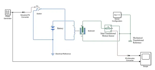
BLOCK EXPLANATIONS:
- PULSE GENERATOR
The pulse generator block generates square wave pulse at regular intervals. The block waveform parameters, amplitude, pulse width, period and phase delay, determine the shape of the output waveform.
The pulse generator block can emit scaler, vector, or matrix signals of any real data type.
The block output can be generated in Time-based or Sample based modes, determined by the pulse type parameter.
- Simulink – PS Converter
The Simulink-PS Converter block converts the input Simulink® signal into a physical signal. Use this block to connect Simulink sources or other Simulink blocks to the inputs of a Physical Network diagram. To convey signal conversion while taking up minimal canvas space, the block icon changes dynamically based on whether it is connected to other blocks.
- Switch
The block represents a switch controlled by an external physical signal. If the external physical signal PS is greater than the threshold, then the switch is closed, otherwise the switch is open. The closed resistance is defined by parameter R_closed, and the open conductance is defined by parameter G_open. Both parameters must be greater than zero.
- Battery
This block models a battery. If you select Infinite for the Battery charge capacity parameter, the block models the battery as a series internal resistance and a constant voltage source. If you select Finite for the Battery charge capacity parameter, the block models the battery as a series internal resistance plus a charge-dependent voltage source defined by:
V = Vnom*SOC/(1-beta*(1-SOC))
where SOC is the state of charge and Vnom is the nominal voltage. Coefficient beta is calculated to satisfy a user-defined data point [AH1,V1].
- Solenoid
This block implements the electrical and mechanical characteristics of a solenoid. Parameterization is in terms of two points [X1,F1] and [X2,F2] on its force-stroke curve for a 100 percent duty cycle at Rated voltage Vdc and Rated current Idc where X2>X1>0 are stroke values and F1>F2>0 are corresponding forces. The plunger fully in (i.e. air gap closed) corresponds to X=0, and pull-in force is assumed to decrease quadratically with the magnitude of X. To ensure the force remains finite, the following condition should hold: X2/X1>sqrt(F1/F2).
The plunger Maximum stroke is implemented as a hard stop, the dynamics of which are set by the Contact stiffness and Contact damping parameters. The same parameters are used to model the contact dynamics when the plunger pulls fully in. The Spring constant parameter is used to implement a spring force that pulls the plunger out, and can be set to zero.
- Ideal translational motion sensor
This block measures velocity or displacement in a mechanical translational network. The sensor is ideal since it does not account for inertia, friction, delays, energy consumption, and so on.
The physical signal ports V and P report the velocity and position, respectively, of port R relative to port C. The measured velocity is positive when the velocity at port R is greater than the velocity at port C.
- PS-Simulink converter
Converts the input Physical Signal to a Simulink output signal.
The unit expression in 'Output signal unit' parameter must match or be commensurate with the unit of the Physical Signal and determines the conversion from the Physical Signal to the Simulink output signal.
- Solver configuration
Each physical network represented by a connected Simscape™ block diagram requires solver settings information for simulation. The Solver Configuration block specifies the solver parameters that your model needs before you can begin simulation.
Each topologically distinct Simscape block diagram requires exactly one Solver Configuration block to be connected to it.
- Reference (Electrical and mechanical)
The all reference must be connected to the ground.
OUTPUT
The Output of the graph is switch is closed for 2sec and then released. So the solenoid which receives electrical current is electromagnetism and battery power to the electromagnet pulls the metal arm to hitting the actions, producing a sound.
RESULTS
Thus the Simulink model of doorbell using solenoid blocks was plotted.
2) Temperature control of a fan
AIM:
To Use a thermistor to sense the temperature of a heater & turn on or turn off the fan.
Requirements
signal builder
Simulink-PS Converter
Controlled temperature source
Thermistor
Battery
Voltage sensor
Resistor (load)
PS-simulink converter
Constant
Switch
Scope
Reference
Simulink model
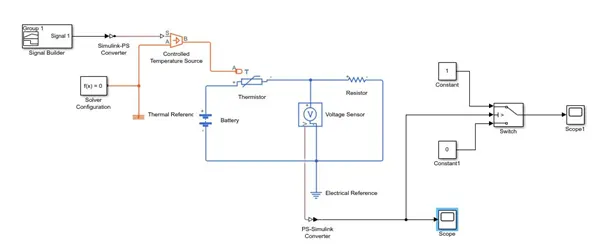
Circuit explanations:
The signal builder the useful to the plot a temperature and time. The output of the signal builder first order filtering signal then connects to the Simulink-PS converter. Thermistor series connect to the battery the receives electrical power. The voltage senor connect a one end of thermistor negative and another end connect a battery negative terminal. the voltage sensor output connected to the fan. i.e. switch. All the output connect to a scope and solver configuration is used to a all system is equal to zero.
VOLTAGE SENSOR
The block represents an ideal voltage sensor, that is, a device that converts voltage measured between any electrical connections into a physical signal proportional to the voltage.
Connections + and - are conserving electrical ports through which the sensor is connected to the circuit. Connection V is a physical signal port that outputs voltage value.
CONDTIONS:
To set a temperature signals by given below
Temperature source: 200C from 0 to 10sec,
270C from 10 to 30sec,
230C from 30 to 50sec.
Fan conditions: ON if the temperature above 250C,off otherwise
OUTPUT WAVEFORM
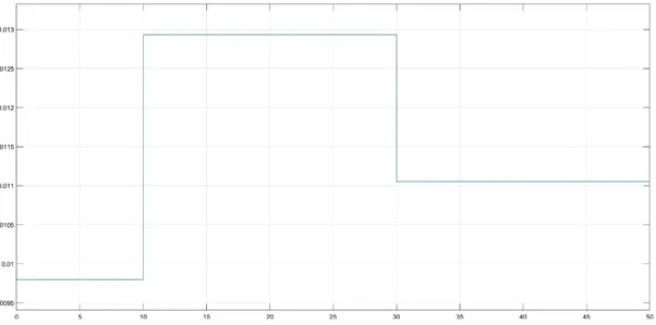
The above of the wave form plot a voltage and time. this graph the fan condition 250c is turn ON and otherwise turn OFF. The 250c fan voltage is 0.0127v is achieved.
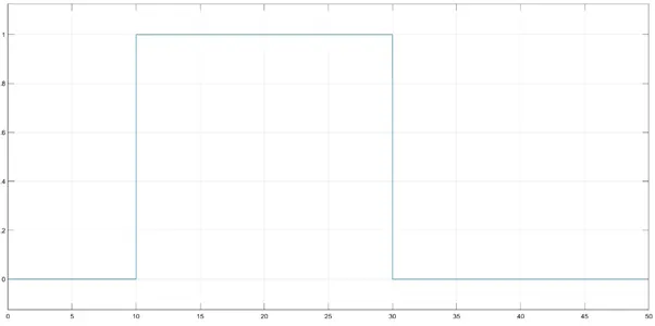
The above wave form is a switch condition output. The switch operated on the logical states. 1 is ON condition and otherwise OFF condition.
REULTS
Thus the thermistor to sense the temperature of a heater & turn on or turn off the fan was satisfied.
Fan turn ON 25oC and otherwise OFF.