Project
PROJECT IN SIMULINK FOR MECHANICAL ENGINEERS AND ELECTRICAL ENGINEERS
AIM:
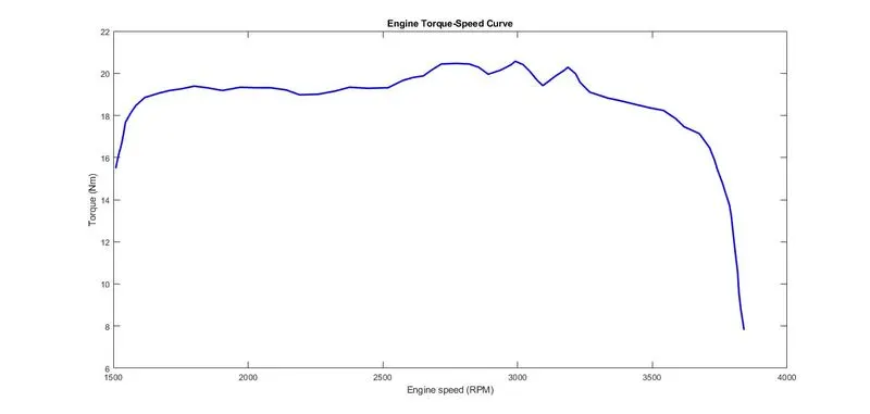
To analysis and designing for an BAJA ATV model with Continuously Variable Transmission(CVT) and plot a curve between Engine Speed (RPM) Vs Torque curve by using simulink model.
INTRODUCTION :
Transmission system for any vehicle is basically meant to transmit the power supplied by the
engines to the wheels, to thereby propel the vehicle. Using the transmission system we can
vary the torque and speed as per the vehicle requirements. Automobile transmission systems
have seen a numerous changes over the years.
Types of Transmission systems:
Based on the gear shifting mechanism transmission system may be classified as:
• Manual Transmission
• Automatic Transmission
Manual Transmission
In a manual transmission system the gear ratios shifting is done manually with the help of
lever. Use of a clutch assembly is mandatory in such case to cut down the power from the
engine during shifting.
Automatic Transmission
It is a type of transmission system in which the shifting of gear ratios is achieved
automatically freeing the driver from shifting the gears manually. It provides with a wide
range of ratios.
Based on the layout, the transmission system may be classified as
• Front Wheel Drive
• Rear Wheel Drive
• All-Wheel Drive
Front Wheel Drive
If the drive from the engine is given to the front wheels of the vehicle then the system is said
to be front wheel drive.
Rear Wheel Drive
If the drive from the engine is given to the rear wheels of the vehicle then the system is said to
be rear wheel drive.
All-Wheel Drive
If the drive from the engine is given to all the four wheels of the vehicle then the system is
said to be all-wheel drive.
For an all-terrain vehicle as the vehicle is said to run on different terrains, either all-wheel
drive or rear wheel drives are suitable. For the purpose of reducing complexity and weight
rear wheel has been chosen.
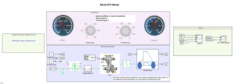
SIMULINK MODEL DIAGRAM FOR BAJA ATV MODEL :
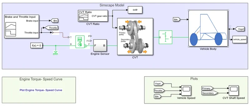
BLOCK EXPLANATIONS :
1. BRAKE & THROTTLE INPUT :
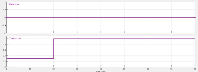
In this project, The brake & throttle input is fed to the signal builder.the signal builder consists of 2 signal. one is brake and anothe one is throttle. the brake signal always zero.an throttle signal is requirements to the input and corresponding output.
2. ENGINE :
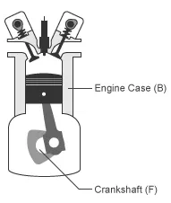
in this project, generic engine used and The Generic Engine block represents a general internal combustion engine. This block is a suitable generic engine for spark-ignition and diesel. Speed-power and speed-torque parameterizations are provided. A throttle physical signal input specifies the normalized engine torque. Optional dynamic parameters include crankshaft inertia and response time lag. A physical signal port outputs the engine fuel consumption rate based on the fuel consumption model that you choose. Optional speed and redline controllers prevent engine stall and enable cruise control.
Engine Speed, Throttle, Power, and Torque
By default, the Generic Engine block uses a programmed relationship between torque and speed that is modulated by the throttle signal.
The block evaluates engine power demand as a function of engine speed, g(Ω). The function provides the maximum power available for a given engine speed, Ω. The block parameters—Maximum power,Speed at maximum power,and Maximum speed— normalize this function to physical maximum torque and speed values.
The normalized throttle input signal T specifies the actual engine power. The power is delivered as a fraction of the maximum power possible in a steady state at a fixed engine speed. It modulates the actual power delivered, P, from the engine: P(Ω,T) = T·g(Ω). The engine torque is τ = P/Ω.
WORKING :
in this project, generic engine input to the throttle and output of the continuous variable transmission(cvt).the engine block also connect the engine sensor.which sense the signal to the cvt secondary pulley.
3. CONTINUOUS VARIABLE TRANSMISSION ( CVT ) :
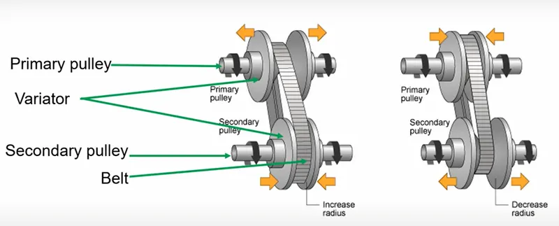
This automatic transmission, instead of an automated gearbox, uses two pulleys of variable diameter connected by a belt. One pulley is turned by the engine, while the other is connected to the differential to run the wheels.
Smooth And Comfortable
CVT uses two pulleys having variable diameters that help the transmission achieve infinite gear ratios. Thanks to this, the flow of power from the engine to wheels is continuous and uninterrupted. With no mechanical gears & shafts, the speed transition is smooth while accelerating or de-accelerating. All of this means an effortless driving experience with a lot of comfort.
Superb Performance
In the CVT technology, there is a Transmission Engine Controller Unit in place to operate this hydraulic system. The function of this hydraulic system is to control the motion of one pulley to achieve the required speed ratio. The change of speed is managed by the cone-pulley position change which is gradual and smooth.An easy visualisation is a set of two diametrically opposed cones, where the belt is always moving between the thick end and narrow end of the two cones to keep the engine in its optimum operating RPM (revolutions per minute). This gives the desired acceleration and power whenever you need it. Hence, you get both superior performance and matchless comfort.
Fuel Efficiency
In effect, a CVT has an unlimited number of gear ratios. This means that the engine will always be running at the most efficient RPM, for any given speed. And since the engine is allowed to operate in the highest possible efficiency band, it delivers enhanced fuel efficiency in different driving conditions.
SIMULINK DIAGRAM FOR CVT :
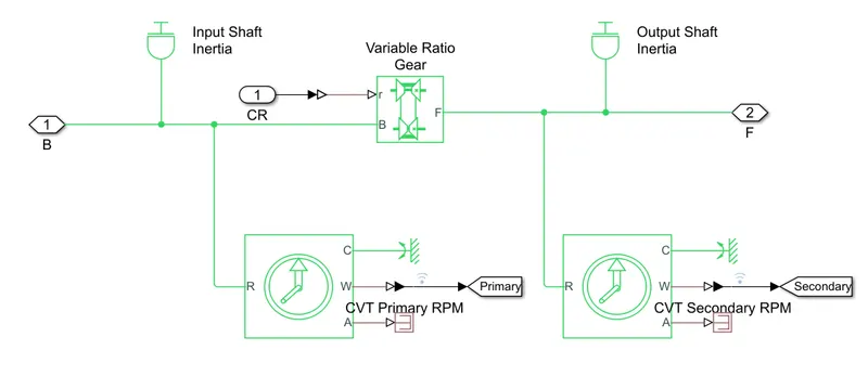
The cvt consists of a two pulleys are primary and secondary pulleys. primary pulley connect to the gear ratio and seconary pulley connect with engine output.While those two transmission types work on the same basic principle, CVTs are different in that they don’t have any gears. The most common type uses two pulleys connected with a belt or chain. One pulley is attached to the engine crankshaft, called the driving pulley. Powered by the engine, it uses the belt to turn the second one, called the driven pulley, which sends that power to the wheels. Each pulley is made up of two pieces, which can move closer together or farther apart. As they do, the pulley’s diameter changes, with each pulley becoming progressively larger or smaller to offset the other and keep the belt tight.
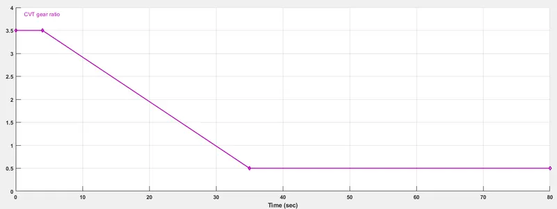
The gear ratio input is used to the signal builder.the below diagram for cvt gear ratio,
4. GEAR :
A CVT gearbox has a relatively simple arrangement of two cone-shaped pulleys with a V-shaped drive belt connecting them. One pulley is attached to the engine, while the other is joined to the wheels. When you press the accelerator, the engine revs and the cone moves according to the amount of power asked for. The other cone adjusts accordingly so that the drive belt maintains the same tension, and this is what determines how the car accelerates.
As the two cones move independently, that means there are no set gear ratios as you would find in a conventional auto or manual, so a CVT is, in effect, a single-speed unit with infinite gear ratios available. That also explains why CVT-equipped cars have a familiar high-revving character, because engine revs aren't related to wheel speed.
5. VEHICLE BODY :
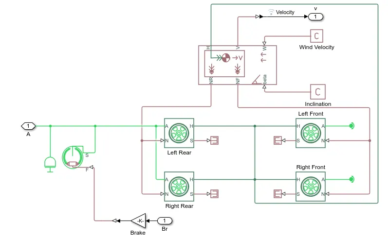
The Vehicle Body block represents a two-axle vehicle body in longitudinal motion. The vehicle can have the same or a different number of wheels on each axle. For example, two wheels on the front axle and one wheel on the rear axle. The vehicle wheels are assumed identical in size. The vehicle can also have a center of gravity (CG) that is at or below the plane of travel.
The block accounts for body mass, aerodynamic drag, road incline, and weight distribution between axles due to acceleration and road profile. Optionally include pitch and suspension dynamics. The vehicle does not move vertically relative to the ground.
The block has an option to include an externally-defined mass and an externally-defined inertia. The mass, inertia, and center of gravity of the vehicle body can vary over the course of simulation in response to system changes.
Model
The vehicle axles are parallel and form a plane. The longitudinal, x, direction lies in this plane and perpendicular to the axles. If the vehicle is traveling on an incline slope, β, the normal, z, direction is not parallel to gravity but is always perpendicular to the axle-longitudinal plane.
This figure and table define the vehicle motion model variables.
Vehicle Dynamics and Motion
Vehicle Model Variables
| Symbol | Description |
|---|---|
| g | Gravitational acceleration |
| β | Incline angle |
| m | Mass of the vehicle |
| h | Height of vehicle center of gravity (CG) above the ground |
| a, b | Distance of front and rear axles, respectively, from the normal projection point of vehicle CG onto the common axle plane |
| Vx | Velocity of the vehicle. When Vx > 0, the vehicle moves forward. When Vx < 0, the vehicle moves backward. |
| Vw | Wind speed. When Vw > 0, the wind is headwind. When Vw < 0, the wind is tailwind. |
| n | Number of wheels on each axle |
| Fxf, Fxr | Longitudinal forces on each wheel at the front and rear ground contact points, respectively |
| Fzf, Fzr | Normal load forces on each wheel at the front and rear ground contact points, respectively |
| A | Effective frontal vehicle cross-sectional area |
| Cd | Aerodynamic drag coefficient |
| ρ | Mass density of air |
| Fd | Aerodynamic drag force |
ALL TERRAIN VEHICLE ( ATV ) :
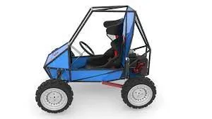 The term ATV stands for All Terrain Vehicle. It is also known as a quad or quadricycle type vehicle. An All-Terrain motor vehicle could have three, four or even six wheels. Unlike a motorcycle, generally, the ATVs have more than two wheels. This vehicle runs on low-pressure tires. However, it has handlebars instead of wheel for controlling the steering.
Most earlier generation ATVs had large balloon tires instead of a mechanical suspension. However, by the early 1980s, manufacturers introduced All Terrain Vehicles with better components like suspension, racks and lower-profile tires. In the late 1980s, due to safety issues with three-wheel ATVs, manufacturers upgraded them to four-wheel models. Later, manufacturers like Polaris designed & developed the ATVs with six wheels for specialised operations such as military.
Modern ATVs employ advance features such as liquid-cooled engine and Twin spark-plugs. Some also offer independent suspension, automatic transmission, and a 4-wheel drive system etc. Manufacturers categorize modern ATVs in the following catogaries.:
- Utility
- Sport
- Children's
- Side-by-Side or SxS
- 50cc Gas
Honda, Suzuki, Yamaha and Kawasaki are some of the ATV manufacturers in the world. CFMOTO, Tracker Offroad, and Polaris are some of the American ATV manufacturers.
SIMULINK RESULTS OR GRAPHS :
1. ENGINE TORQUE AND SPEED CURVE
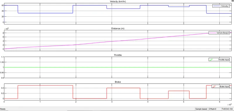
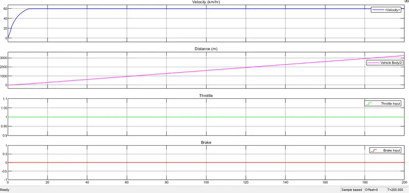
2. OUTPUT FOR VELOCITY,DISTANCE,THROTTLE AND BRAKE :
In this graph of throttle input is 1 and Brake is 0.
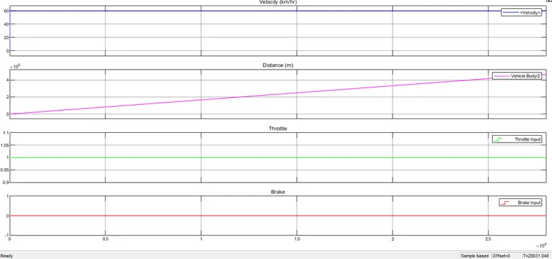
Therefore the velocity is 60 km/hr and 5 meter distance. suppose we take an brake is applied to corresponding time so the speed is reduced and velocity also decreased.
3. CVT SHAFT SPEED CURVE :
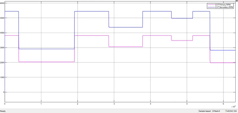
cvt shaft speed curve for cvt primary and secodary speed. this is variable for the corresponding changing to the throttle and brake.below figure for throttle is 1 and brake is 0.
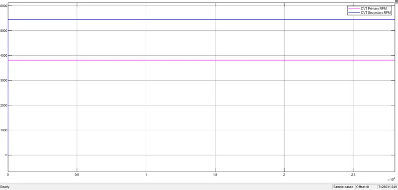
Therefore the primary speed of cvt 3800rpm and secondary speed of cvt 5500rpm depends upon the gear ratio.suppose we take an applied for brake so cvt of speeds also changes.
we take an stop time 200sec and throttle is 1 also brake is 0. so the output of velocity is 60km/hr constant and distance moving to the 3000m above.
so the the over all output for the resulted and brake is applied corresponding parameter to be changed.
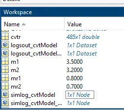
WORKSPACE :
Results :
Thus the BAJA ATV model with Continuously Variable Transmission(CVT) was analyzed and also graph between engine torque and speed were plotted.