Week-6 Challenge: EV Drivetrain
Week 6 Challenge : EV Drivetrain
Q1.Which types of power converter circuits are employed in electric and hybrid electric vehicle?
Soln:
Power converters are devices that can convert electrical energy from one form and level to another optimized form
and level for specific loads. In the Hybrid and Electric Vehicles , 3 types of power converters are used , they are -
1. DC-AC converter : These converters are used to convert DC power to Ac power. They are also known as inverter. They are used in
case of AC motor drives in HEV and EV. The power from battery pack comes to inverter and it is converted to AC power.
This power is then fed to the AC tractive motor (generally induction motor) to run the vehicle.
2. AC-DC converter : They are also known as Rectifier. It converts the AC supply into DC power. They can be of 3 types—half wave, full wave
and bridge rectifier. The rectifier is employed in the battery charging circuit of hybrid and fully electric vehicles.
3. DC-DC converter : It convert Dc source voltage to another level of dc voltage. They are also known as choppers. The dc-dc converter in HEV
and Ev‘s are used to change the high voltage from the battery pack to a lower voltage (12 V or 48 V) , that powers the headlamps,
interior lights, windows, side mirrors, wipers and other auxiliary systems.
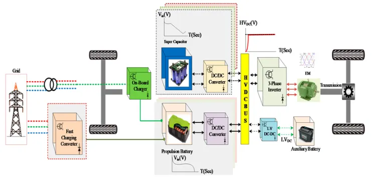
Q2. An Electric Vehicle's powertrain with 72V battery pack in shown in the diagram below. The duty ratio for acceleration operation is 'd1'
and for the braking operation the duty ratio is 'd2'. The other parameters of the electric vehicle is given below,
Motor and Controller Parameters:
Rated Armature voltage= 72 V
Rated armature current= 400 A
Ra= 0.5Ω, KΦ= 0.7 Volt second
Chopper Switching frequency= 400 Hz
The vehicle speed-torque characteristics are given by the below equation

What is EV steady state speed if duty cycle is 70% ?
Soln:
Given block diagram arrangement-
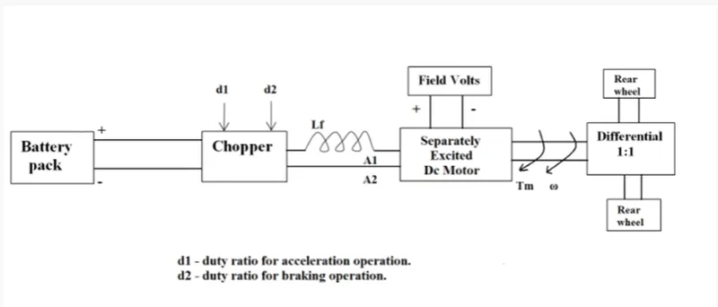
Given parameters are-
Rated voltage of the battery pack = 72 V
Rated Armature voltage= 72 V
Rated armature current= 400 A
Armature resistance, Ra= 0.5Ω,
KΦ= 0.7 Volt second
Chopper Switching frequency= 400 Hz
Duty Cycle = 70% =0.7
The vehicle speed-torque characteristics are given by the below equation-
Tv=24.7 + 0.0051 ω2
Now, with 70% duty cycle the average voltage during the cycle will be,
V = Rated Voltage * 70%
=> V =72 * 0.7 =50.4 V
The speed of dc motor can be expressed as –
ω = V/KΦ – (Ra/( KΦ)^2)*T
putting the motor parameters in the above equation we get-
ω = 50.4/0.7 – (0.5/0.7^2)*T
=> ω = 72 - 1.0204 T
=> T = 70.56 - 0.98 ω
Putting this value of torque in the vehicle speed torque characteristics equation , ωe achieve
70.56 - 0.98 ω = 24.7 + 0.0051 ω2
=> 0.0051 ω2 + 0.98 ω – 45.86 = 0
Solving the above quadratic equation for ω, we get ,
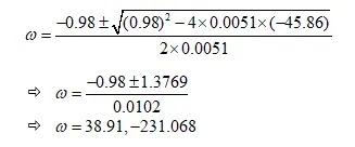
Considering the forward movement of the vehicle, the value of ω cannot be negative.Hence, the steady state speed
of the motor during duty cycle will be, ω = 38.91 rad/s
Q3. Develop a mathematical model of a DC Motor for the below equation using Simulink.
ω">ω= V/Kϕ">ϕ -Ra/Kϕ">ϕ^2 .T
Soln:
The given equation of speed is-
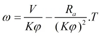
The equation is modeled in Simulink as follows-
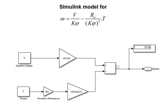
The input values such as Voltage , Torque, armature resistance, K and Φ , are fetched from the workspace. The model is simulated and results are taken.
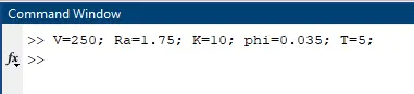
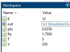
fig. input from matlab main window
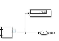
fig. display output
Q4. Refer to the blog on below topic:
Induction Versus DC brushless motors by Wally Rippel, Tesla
Explain in brief about author’s perspective.
Soln:
In the blog post Induction vs Dc brushless motor , the author Willey describes about technology changes in the automotive industry. He starts by asking a fairly common question that which is the best engine as various types are available. But it is all down to personal requirements like price and performance , so no engine is best. In the blog, he widely talked about induction motors and DC brushless motor in the context of Fully Electric and Hybrid Electric vehicles. He shed light in the fact that previously used Pb-acid batteries, dc motors and contactors are nowadays got replaced by better and efficient Li-ion batteries, dc brushless motors and induction motors.
The author then digs into the constructional details of the two motor drives. The Dc Brushless motor, uses permanent magnets in the rotor to generate magnetic field. The stator is made up of thin , stacked laminations. The magnetic fields enter the stator and produces the required torque by interacting with current flow in the winding. It can maintain constant torque and the conversion of electrical energy to mechanical energy is optimally efficient.
Both the Induction motor and dc brushless motor share the same stator construction, but they differ in the rotor. In the induction motor, the stator has 3 sets of distributed windings for 3-phases. While rotor is laminated core with conductors on its outer periphery which are short-circuited. The rotor derives its voltage and currents from the energized stator through electromagnetic induction of a rotating a magnetic field. There’s a difference between the applied electric frequency and rotational frequency of the rotor as it tries follow the original magnetic field. This difference helps to produce the required torque.
The induction motor can be started from 3 phase ac outlet easily and cannot operate from DC. On the other hand the DC Brushless motor requires dc supply and also needs inverter to connected for starting. The Induction motor is essentially a constant speed motor. Also peak torque is less compared to DC type machines.
Rippel states that in 90’s all the electric vehicles except one were powered by DC brushless drives , but nowadays all the Hybrids use DC brushless drives. The induction drives were implemented on the GM EV-1; the AC Propulsion vehicles, including the tzero; and the Tesla Roadster. The DC Brushless and induction drives are different only in rotor and inverter controls. The DC Brushless requires an absolute position sensor and induction drive needs a speed sensor.
The rotor in Dc brushless generates less heat than the induction drives. They also operate at unity power factor that allows dc brushless drives to have higher peak point efficiency. On the other hand induction drive can best upto 85% power factor, making them less efficient in peak point. However, Dc brushless drives suffer more losses in the form I2R losses , eddy and hysteresis losses as it cannot adjust the magnetic flux density B because of permanent magnets. Since Induction motor have no magnets, B can be adjusted as per load requirement. Hence in the long run the average efficiency of induction machine in higher than the brushless counterpart.
Author states that although induction machines are cheap to make and takes up less losses than dc brushless of same size, they are hard to control. Control is simpler in DC brushless machines. Achieving stability over the entire torque-speed range and over temperature is a much difficult task with induction than with DC brushless machine.
Rippel concludes by saying that he got no winners. The Brushless drives will rule the HEV and PHEV sectors, while induction drives likely to excel for the high performance EVs. As there are so many similarities in hardware level of both drives , it is possible to that we will observe them working in synergy in the coming times.