Week-6 Challenge: EV Drivetrain
EV DRIVETRAIN
AIM:
- To identify the Power Converters employed in EV and HEV
- To calculate the Steady State Speed of EV
- To develop a Mathematical Model of DC Motor using Simulink
- To brief about the Author’s Perspective in the Article
SOLUTION:
- Which types of power converter circuits are employed in electric and hybrid electric vehicle?
Power Converters:
Power electronic technology deals with processing and controlling the flow of electrical energy in order to supply voltages and currents in a form that optimally suited for end user’s requirements.
A power electronic converter uses power electronic components such as SCRs, TRIACs, IGBTs, etc. to control and convert the electric power. The main aim of the converter is to produce conditioning power with respect to a certain application.
Depending on the type of function performed, power electronic converters are categorized into following types.
- AC to DC = Rectifier: It converts AC to unipolar (DC) current
- DC to AC = Inverter: It converts DC to AC of desired frequency and voltage
- DC to DC = Chopper: It converts constant to variable DC or variable DC to constant DC
- AC to AC = Cycloconverter, Matrix converter: It converts AC of desired frequency and/or desired voltage magnitude from a line AC supply.
Power Converters in EV:
- AC to DC Converters:
AC to DC Converters is used in EV Battery Chargers. The AC Power Supply from Grid is converted into DC Supply to Charge battery
- DC to AC Converters:
For EV using Induction Motors, DC to AC Converter is used to convert DC Power Supply from the Battery into AC Power Supply as required by the Induction Motor.
- DC to DC Converters:
In EV with High Voltage Rating Batteries, To give Power Supply to Sub-components, sensors and control modules, The High Voltage DC is stepped down to Low Voltage by using DC to DC Converters. Also used as DC Drive, to Control DC Motors.
2.An Electric Vehicle's powertrain with 72V battery pack in shown in the diagram below. The duty ratio for acceleration operation is 'd1' and for the braking operation the duty ratio is 'd2'.
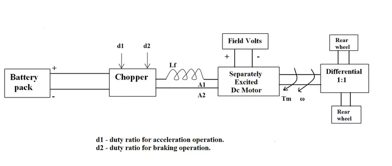
The other parameters of the electric vehicle are given below,
Motor and Controller Parameters:
Rated Armature voltage= 72 V
Rated armature current= 400 A
Ra= 0.5Ω, KΦ= 0.7 Volt second
Chopper Switching frequency= 400 Hz
The vehicle speed-torque characteristics are given by the below equation

What is EV steady state speed if duty cycle is 70%?
Given:
Battery Pack Rated Voltage = 72V
Duty Cycle = 70% = 0.7 KΦ
Armature Resistance Ra = 0.5Ω
Chopper Switching Frequency = 400Hz
Motor Constant KΦ = 0.7 Volt Second
Vehicle Speed Torque Characteristics è T = 24.7+(0.0051) ω2
Solution:
Applied Terminal Voltage of Motor = Battery Voltage*Duty Cycle = 72*0.7=50.4V
General Torque Equation of a DC Motor is
Substituting Values T = = 70.56 – 0.98ω
Equating with the Given Torque Equation
24.7+(0.0051) ω2 = 70.56 – 0.98ω
0.0051 ω2 + 0.98ω – 45.86 = 0
Solving the Quadratic Equation gives
ω = 38.915 or -231.0718
As the Speed cannot be negative, ω = 38.915 rad sec-1 = 371.8 RPM
3.Develop a mathematical model of a DC Motor for the below equation using Simulink.
ω= V/Kϕ - Ra/Kϕ^2 .T
Simulink Model:
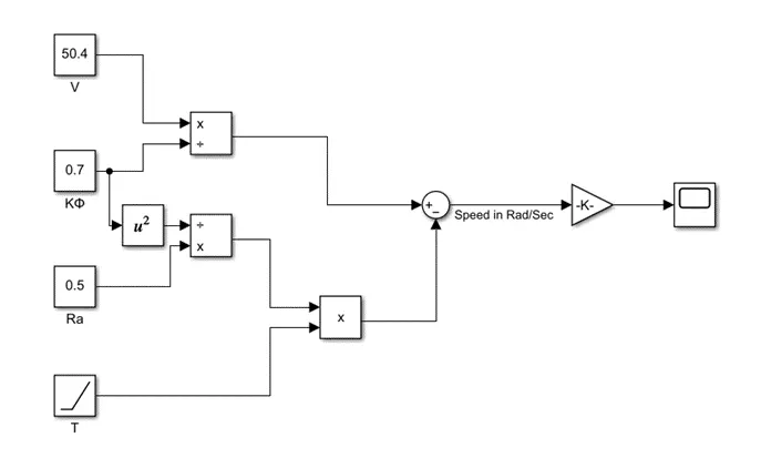
Description of Simulink Model:
The Simulink Model is modelled to execute the Given Equation which is the Mathematical Model of DC Motor
V, Kϕ, Ra values are assigned through Constant Blocks.
Torque value is given as a Ramp Signal.
The Resultant Speed value obtained after execution of the equation is in Radian per Second. It is converted into RPM by multiplying (Gain Block) by 9.55
Output:
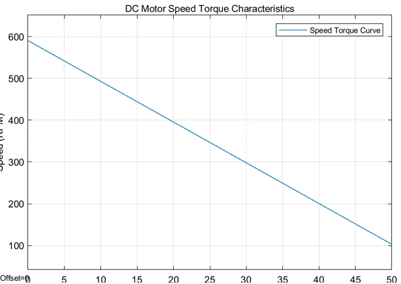
The Output Curve is a line with negative slope which means as the Torque increase Speed decreases.
4.Refer to the blog on below topic: Induction Versus DC brushless motors by Wally Rippel, Tesla . Explain in brief about author’s perspective.
Author’s Perspective:
In this Article, Author compares Induction Motor and DC Brushless Motor – its characteristics, advantages, disadvantages and their future in EV Application.
As the New technologies evolve, Old Technologies get outdated and gets left behind. But Author still hopes that Induction Motors and Brushless Machines will continue to exist for many more years.
Induction Motors can be operated without drives. When Run on Utility Power Starting Torque and Peak Torque are limited and speed is constant as it is proportionate to Frequency. When a Converter Circuit is used Speed can be varied but the Torque Capability is still low compared Brushless Motor.
Brushless DC Motor must need DC Drive to continuously vary Magnitude and Polarity of the Current to run the Motor. In DC Brushless Motor, Rotor heat generated is much less and Rotor cooling is much easier. Peak Point efficiency is higher and can run at utility Power Factor.
In DC Motor, The Magnetic Field produced can not be varied according to required output. Due to this even at Low Speed or Low Torque, Iron and Copper loss are higher. But in Induction Machine, Using the Drive V/f can be adjusted which is directly proportionate to Magnetic Field by which Losses can be reduced optimally.
In DC Motors, as the size increases losses also increases but not necessarily in induction motors
DC Motor requires an Absolute Position Sensor to run while the Induction Motor can run with a speed sensor.
The PM used in DC Motor costs high and also difficult to handle.
Induction Motor are more difficult to Control. Control Laws are complex. Due to this Development costs are high but no recurring cost.
Author expects DC Brushless Motor to dominate Hybrid and Plugin Hybrid Vehicles while Induction Motor will dominate High-performance Pure Electric. And also Author expects both Motor will be used side by side in future.
CONCLUSION:
- Power Converters employed in EV and HEV are AC to DC Converter, DC to AC Converter and DC to DC Converter.
- For the given data, Steady State speed of EV is 372 RPM
- Simulink Model of the Mathematical Model of DC Motor is created
- Author’s perspective in the Article is briefed.