Week-6 Challenge: EV Drivetrain
Aim:- EV Drivetrain
Objective:-
- To identify the types of power converter circuits employed in electric and hybrid electric vehicles.
- To calculate the steady-state speed of an EV with given inputs if the duty cycle is 70%.
- To develop a mathematical model of a DC motor using Simulink.
- Refer to the blog and explain in brief the author’s perspective.
Q1. Which types of power converter circuits are employed in an electric and hybrid electric vehicle?
what are the Power Converter circuits?
A power converter is an electrical circuit that changes the electric energy from one form into the desired form optimized for the specific load. A converter may do one or more functions and give an output that differs from the input.
A device that increases or decreases the voltage (AC or DC) of a power source depending on the application. A converter that increases voltage is called a step-up converter and a converter that decreases voltage is called a step-down converter. In EVs/HEVs step-up and step-down converters are combined into one unit. An application of a step-up converter is converting EV/HEV battery voltage (typically 180-300 volts) to about 650 volts to power the traction motor. An advantage of using a converter to increase the voltage from the battery is a smaller and less expensive battery may be used while still utilizing an efficient high voltage motor. An application of a step-down inverter would be decreasing the high voltage direct current (DC 180-300 volts) from the HEV/EV battery to low voltage (12-14 volts) DC that can be used to charge the 12-volt auxiliary battery and operate light load devices such as lighting, radio, and windows.
The Power Electronic Converter can be classified into six types:-
- Diode Rectifier.
- AC to DC Converter (Controlled Rectifier)
- DC to DC Converter (DC Chopper)
- AC to AC Converter (AC voltage regulator)
- DC to AC Converter (Inverter)
- Static Switches.
In EVs, the Fuel Cell (FC) stack, battery bank, and Supercapacitors (SCs) bank are usually used as clean energy sources. . In order to design highly efficient converters for the EV's power system, advanced DC/DC, AC/DC and DC/AC converters are required to adapt the output voltage and current levels with high power quality.
DC to DC Converter (DC Chopper):-
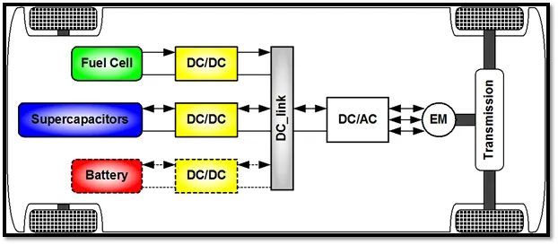
Electric Vehicles (EVs), Hybrid Electric Vehicles (HEVs) and Fuel Cell Electric Vehicles (FCEVs) have been typically proposed to replace conventional vehicles in the near future. ... DC-DC converters can be used to interface the elements in the electric power train by boosting or chopping the voltage levels.
DC-to-DC converters are used to reduce High voltage DC input to low voltage DC output for some specific appliances. They are also used to isolate some highly sensitive components in a circuit from other components of the circuit to avoid any kind of damage.
Electric vehicles (EV) use two different power systems; a high-voltage battery (200 to 450 VDC) for traction and a low-voltage (12 V) one for supplying all the electric appliances in the vehicle. Traditionally the low-voltage battery was charged from the alternator, but in today's vehicles, it gets its power from the high-voltage battery pack. However, in specific electric car architectures, this low voltage battery should be ready to help recharge the high-voltage battery pack in order to provide energy for cranking the car. This means that the onboard DC-DC converter must be bi-directional and very efficient as well as highly reliable in order to run the complex control algorithms needed to ensure an energy-efficient solution.
AC to DC Converter (Controlled Rectifier):-
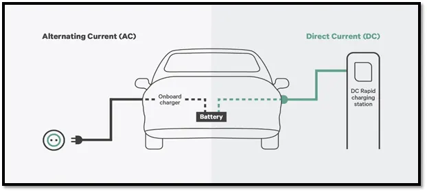
AC to DC converters are most commonly used in Plug-in Hybrid Electric Vehicles (PHEV) & Plug-in Electric Vehicles (PEV). These vehicles get their propulsion power from an external electricity source (charging stations) which is alternating current. The battery needs to be charged using a direct current source. For this purpose, AC to DC converter is employed in a PHEV & PEV.
It's called the "onboard charger" though it really is a converter. It converts power from AC to DC and then feeds it into the car's battery. This is the most common charging method for electric vehicles today and most chargers use AC power.
DC to AC Conveter (Inveter) :-
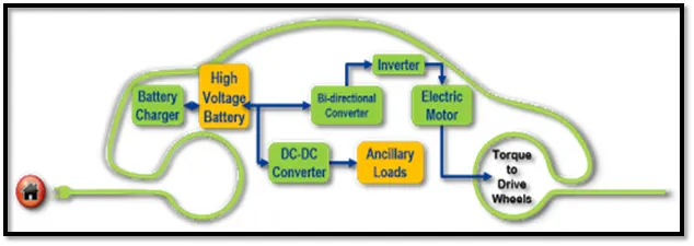
The DC to AC converter is required to convert the dc power to suitable ac power for the electrical machine the power output from the battery pack (DC current) is converted using the inverter to be used in an electric motor (AC current)
Converts direct current (DC) from the battery to alternating current (AC) to be used by other devices such as the traction motor and coolant pump.
Q2. An Electric Vehicle's powertrain with a 72V battery pack is shown in the diagram below. The duty ratio for acceleration operation is 'd1' and for the braking operation the duty ratio is 'd2'.
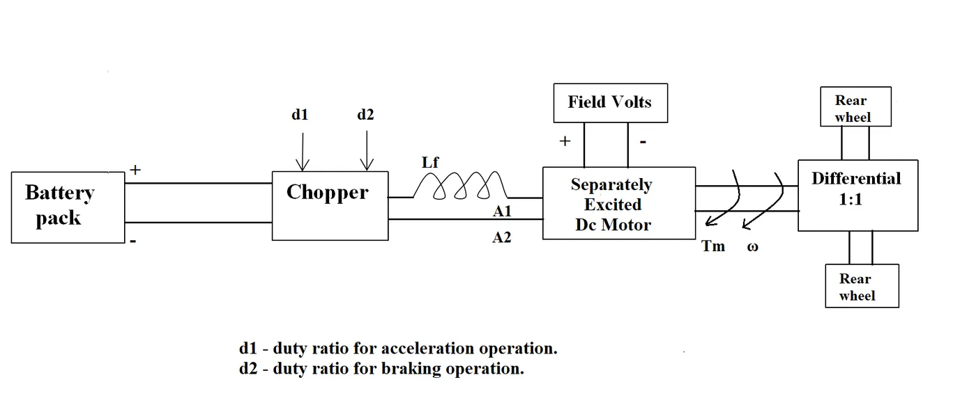
The other parameters of the electric vehicle are given below,
Motor and Controller Parameters:
Rated Armature voltage= 72 V
Rated armature current= 400 A
Ra= 0.5Ω, KΦ= 0.7 Volt second
Chopper Switching frequency= 400 Hz
The vehicle speed-torque characteristics are given by the below equation

What is EV steady state speed if duty cycle is 70%?
Given:-
The following input parameters are given,
- Battery pack voltage (V) = 72V
- Rated armature current = 400A
- Armature Resistance (Ra) = 0.5Ω
- Motor constant (KΦ) = 0.7
- Chopper Switching frequency = 400 Hz
- Duty Cycle = 70%
Solution:-
Vehicle Output Voltage (Vv) is given by,
Vv = Battery Voltage (V) * Duty Cycle
Vv = 72 * 0.70
Thus, Vehicle voltage = 50.4V
Now, Equation for Vehicle torque is given by: -
Tv = V*K/(w*k^2)
Where;
Tv = Vehicle Torque (N-m)
Vv = Vehicle voltage (Volts)
ω = steady state speed of vehicle (rps)
K∅ = Motor constant
Ra = Armature Resistance
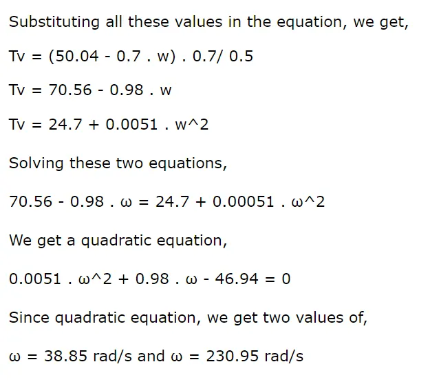
We take the positive value;
Steady state speed of vehicle = = 38.85 rad/s.
Q3. Develop a mathematical model of a DC Motor for the below equation using Simulink.
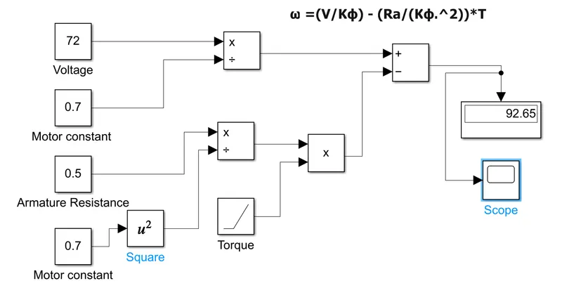
ω= V/Kϕ - Ra/Kϕ^2 .T
Simulink model for the above equation,
Result:-
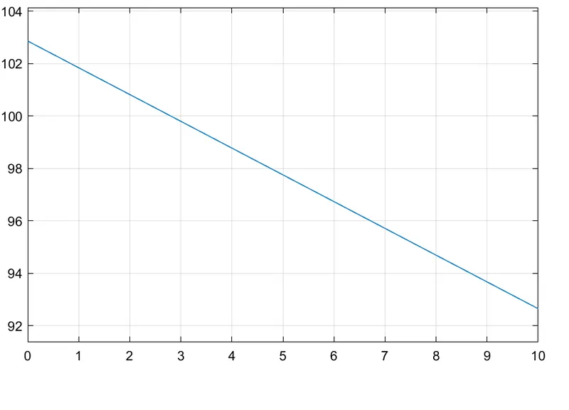
This result shows the torque-speed curve for DC Motor.
Q4. Refer to the blog below topic:
link of the blog:
Induction Versus DC brushless motors by Wally Rippel, Tesla
This blog is about the Walley Reppel perspective about brushless DC and induction motor, who is Walley?
Walley is a proponent of Electric vehicles. He was an engineer at AeroVironment, Where is he helped to develop the EV1 for General Motors. He also worked in Jet propulsion laboratory on electric vehicle battery research, among other projects, a Proponent means someone who is in favour of something.
At the starting of the blog, he said "One Size Does Not Fit All"
he said in that odious world engines are of a different type. He said one would think that, year ago, some tried to figure out which is the best engine and that should be in production but his thought got failed .there is no one is best one .with the different requirement there are different type of engine .such a way he said this true for Brushless DC and Induction Motor. He also said about the evolution of batteries DC bush motor, and contactor controllers
he said the lead-acid battery is replaced by the lithium and brush DC motor with Brushless DC motor or an Induction motor.
Next, he talks a closer look, he gives some closer look at the brushless DC motor and induction motor their technologies, there working.
Also, he speaks about what differentiates them ? in that he told about DC brushless machine that rotor generates the magnetic field with two or more permanent magnet and this magnetic field enters the stator core (a core made up of thin, stacked laminations) and interacts with currents flowing within the windings to produce a torque interaction between the rotor and stator. As the rotor rotates, it is necessary that the magnitude and polarity of the stator currents be continuously varied – and in just the right way - such that the torque remains constant and the conversion of electrical to mechanical energy is optimally efficient. The device that provides this current control is called an inverter. He told one thing that Without an inverter, brushless motors are useless motors.
Then is told about the induction motor drives. he curiously told that stator of the both DC brushless and induction motors have three sets of “distributed windings” the only difference is in the rotor, the induction motor has no magnet it contains steel laminations with buried peripheral conductors. He describes the working of induction motor that Currents flowing in the stator windings produce a rotating magnetic field that enters the rotor. In turn, the frequency of this magnetic field as “seen” by the rotor is equal to the difference between the applied electrical frequency and the rotational “frequency” of the rotor itself. Accordingly, an induced voltage exists across the shorted structure that is proportionate to this speed difference between the rotor and electrical frequency. In response to this voltage, currents are produced within the rotor conductors that are approximately proportionate to the voltage, hence the speed difference. Finally, these currents interact with the original magnetic field to produce forces – a component of which is the desired rotor torque.
he said that induction motor does not require an inverter and the motor has the ability to start under the load .with the fixed utility power dc brushless motor produces no starting torque it needs an inverter .induction motor is not operated from the DC source.
Next, "Brushless or Induction"
He told that back 1990s all EV except one uses the DC brushless drives today all HEV use the DC brushless. Then he gave some comparison between DC brushless and induction motor
| DC Brushless | Induction motor |
| require an absolute position sensor | require an absolute position sensor |
|
less rotor heat is generated, Rotor cooling is easier and peak point efficiency is higher. operate at a unity power factor |
power factor is about 85 %, peak point efficiency higher compare to DC Brushless |
|
strength of the magnetic field produced by the permanent magnets would be adjustable. to get max torque the magnetic field should max at low speed maintained by the inverter and motor current low |
no magnets and B fields are “adjustable,” since B is proportionate to V/f (voltage to frequency).efficiency is maximized due to low magnetic losses |
| Average efficiency is low | Average efficiency is high |
| Permanent magnets are expensive | no magnet there is an advantage in cost |
| they are easy to control | The control laws are more complex and difficult to understand, so difficult to control |
with saying "Still No Winner", he describes that no one is best DC brushless or induction.
Concluded that both are the best as per the requirement.