Week-6 Challenge: EV Drivetrain
AIM:
- To list the types of power converter circuits are employed in electric and hybrid electric vehicle.
- To find the EV steady state speed if duty cycle is 70% for the following Electric Vehicle's powertrain with 72V battery pack in shown in the diagram below.
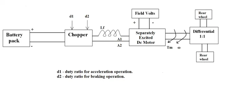
Motor and Controller Parameters:
Rated Armature voltage= 72 V
Rated armature current= 400 A
Ra= 0.5Ω, KΦ= 0.7 Volt second
Chopper Switching frequency= 400 Hz
The vehicle speed-torque characteristics are given by the below equation

- To develop a mathematical model of a DC Motor for the below equation using Simulink.
ω = V/Kϕ -(Ra/(Kϕ^2)) .T
- To Explain in brief about author’s perspective to the blog on below topic:
Induction Versus DC brushless motors by Wally Rippel, Tesla
BODY OF CONTENT:
1. Which types of power converter circuits are employed in electric and hybrid electric vehicle?
Power converters:
The power conversion is the process of converting electrical energy from one form to another. A power converter is an electrical or electro-mechanical device for converting electrical energy. A power converter can convert alternating current (AC) into direct current (DC) and vice versa; change the voltage or frequency of the current or do some combination of these. The power converter can be as simple as a transformer or it can be a far more complex system, such as resonant converter. The term can also refer to a class of electrical machinery that is used to convert one frequency of alternating current into another. Power conversion systems often incorporate redundancy and voltage regulation.
Power converter are classified based on the type of power conversion they do. One way of classifying power conversion systems is according to whether the input and output are alternating current or direct current. Finally, the task of all power converters is to process and control the flow of electrical energy by supplying voltages and currents in a form that is optimally suited for user loads.
Power converters in EV and HEV:
On electric vehicles (EVs), which includes both fuel cell electric vehicles (FCVs) and battery electric vehicles (BEVs), and hybrid electric vehicles (HEVs) the converter, inverter, and controller are integrated into one unit, but each perform different tasks. These electronics generate a lot of heat and have their own dedicated cooling system separate from the engine which includes its own pump and radiator.
Types of Power converters:
Rectifier:
AC-DC converters are referred as a rectifier and are implemented using diodes and thyristors to give an uncontrolled and controlled DC power with unidirectional and bidirectional power flow. An AC-DC converter supplies an electric power from a commercial power system to an onboard high voltage battery. A highly efficient low-cost hybrid with three phase and three level rectifiers is introduced.
A plug in hybrid electric vehicle is a hybrid vehicle which utilizes a battery to power the vehicle’s electric motor. A battery charging system is used to draw energy from the grid, store it in a battery, and release it to the power device. The charger must be fully adapted to the battery to prevent battery from damage. The charger system needs to work with any kind of electric.
Rectifier Using PWM Modules
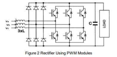
The above figure shows topology using PWM rectifier modules with a very low current rating (20-25%) level of rms current.
Hence it has a low cost potential and provide only the possibility of regenerative braking mode with active filtering, but the DC regulation is difficult.
Vienna rectifier
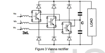
The above figure presents a three-level converter called a Vienna rectifier. The main advantage is low switch voltage, but non typical switches are required. It has high power density and unidirectional power flow. It can also provide UPF.
Universal bridge topology
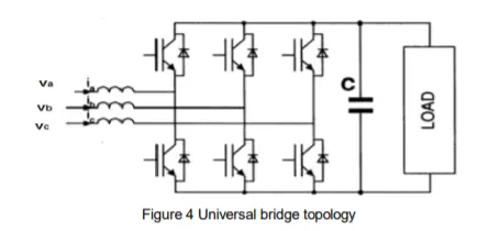
This universal topology has the advantage of using a low-cost three-phase module with a bidirectional energy flow capability. Although, it has disadvantages of a high per-unit current rating, poor immunity to shoot-through faults, and high switching losses.
The most common topology for the HEV battery charger is the two-stage approach with cascaded, PFC AC-DC and controller of the converter. In the PFC AC-DC stage, AC three phase is rectified and boosted with power factor correction. The output of the boost converter is connected to the DC bus. The second stage controlled the output voltage of the converter.
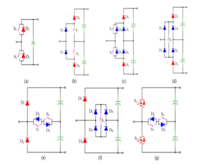
Per-phase circuit of existing Hybrid PFC boost rectifiers: Diodes in Blue: Slow speed diode, Diodes in Red: Fast-Switching diode using SiC Schottky Diode, (a) Two-level rectifier, (b) Three-level NPC rectifier Type I, (c) Three-level NPC rectifier Type II, (d) Three- level NPC rectifier Type III, (e) Three-level T-type rectifier Type I (f) Three-level T-type rectifier Type II (g)
SiC MOSFET & Si Switch Bi-directional Rectifier.
Inverter:
This is used when the vehicle has AC induction motor and the power supply to the motor is through battery which is DC. To convert the DC supply to AC supply the device used is known as inverter. It converts the power from one DC level to another AC voltage and frequency level. If the battery voltage is reduced, then it is step-down converter and if the battery voltage is increased, then it is step up converter.
Converts direct current (DC) from the battery to alternating current (AC) to be used by other devices such as the traction motor and coolant pump.
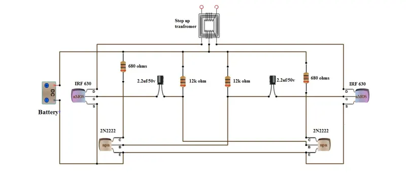
The basic idea behind every inverter circuit is to produce oscillations using the given DC and apply these oscillations across the primary of the transformer by amplifying the current. This primary voltage is then stepped up to a higher voltage depending upon the number of turns in primary and secondary coils.
DC/DC converter:
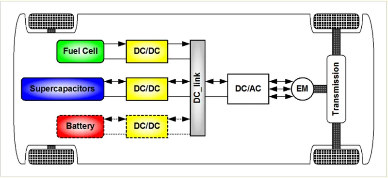
The different configurations of EV power supply show that at least one DC/DC converter is necessary to interface the Fuel Cells, the Battery or the Supercapacitors module to the DC-link. In case of interfacing the Fuel Cell, the DC/DC converter is used to boost the Fuel Cell voltage and to regulate the DC-link voltage. However, a reversible DC/DC converter is needed to interface the Super Capacitors module.
Non-isolated converters
The non-isolated converters type is generally used where the voltage needs to be stepped up or down by a relatively small ratio (less than 4:1). And when there is no problem with the output and input having no dielectric isolation. There are five main types of converter in this non-isolated group, usually called the buck, boost, buck-boost, Cuk and charge-pump converters. The buck converter is used for voltage step-down, while the boost converter is used for voltage step-up. The buck-boost and Cuk converters can be used for either step-down or step-up. The charge-pump converter is used for either voltage step-up or voltage inversion, but only in relatively low power applications.
Isolated converters
Usually, in this type of converters a high frequency transformer is used. In the applications where the output needs to be completely isolated from the input, an isolated converter is necessary. There are many types of converters in this group such as Half-Bridge, Full-Bridge, Fly-back, Forward and Push-Pull DC/DC converters. All of these converters can be used as bi-directional converters and the ratio of stepping down or stepping up the voltage is high.
Chopper:
All the auxiliary devices inside the vehicle like speakers, bluetoothe, head lamps, side lights etc.. which is rated low voltage at 12 V or more approx. , the power supply is given through battery which is high rated voltage(200-800 V) through a device known as chopper which is a DC-DC power converter.
REFERENCES:
https://en.wikipedia.org/wiki/Electric_power_conversion
https://www.intechopen.com/chapters/19583
https://www.irjet.net/archives/V7/i4/IRJET-V7I41019.pdf
- Finding the EV steady state speed if duty cycle is 70% for the following Electric Vehicle's powertrain with 72V battery pack in shown in the diagram below.
Motor and Controller Parameters:
Rated Armature voltage= 72 V
Rated armature current= 400 A
Ra= 0.5Ω, KΦ= 0.7 Volt second
Chopper Switching frequency= 400 Hz
The vehicle speed-torque characteristics are given by the below equation
Given that
duty cycle = 70%
Rated armature voltage = 72 V
Therefore, Voltage supplied to the motor = 72*.7 = 50.4 V
We know that,
ωm = (V/Kφ) – (Ra/ (Kφ^2))*T .....(1)
where,
ωm = Angular spped of the motor (rad/s)
V = Supply voltage to motor (V)
Kφ = Motor constant
Ra = Armature resistance (Ω)
T = Motor torque (N-m)
From (1),
T = (V - ωm * Kφ )*Kφ / Ra .....(2)
Substituting the given values in the (2)
T = (50.4 - ωm * 0.7 )*(0.7/0.5) ......(3)
Substituting the (3) in below given equation
T = 24.7 + 0.0051 *ωm ^2 ......(4)
(50.4 - ωm * 0.7 )*(0.7/0.5) = 24.7 + 0.0051 *ωm ^2
Solving the above equation we get polynomial equation as,
ωm ^2 + 192.1568 ωm - 8882.3529 = 0
By solving, we get
ωm = 38.6 r/s & ωm = -230.664 r/s
By taking positive values ωm = 38.6 rad/s
Therefore, EV steady state speed for a 72V battery back & 70% duty cycle = 38.6 r/s (or) 369 rpm.
3. Develop a mathematical model of a DC Motor for the below equation using Simulink.
ω = V/Kϕ -(Ra/(Kϕ^2)) .T
Given equation:
ω = V/Kϕ -(Ra/(Kϕ^2)) .T
where,
V = Input Voltage
K = motor constant
ϕ = magnetic flux
Ra = armature resistance
T = Torque
Blocks required:
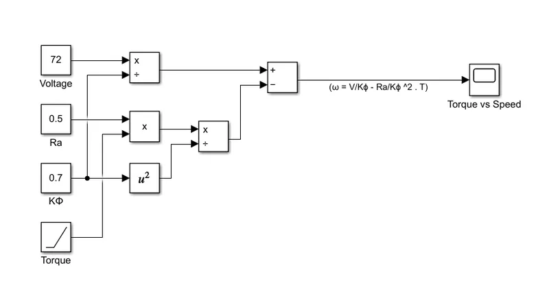
- Constant - Used to give the input constant values to the model such as Rated armature Voltage, motor constant and armature resistance .
- Ramp - Used to give variable input (Torque) to the model with respect to time.
- Divide - Used to divide the values which is required in the equation.
- Product - Used to multiply the values.
- Square - Used to square the values
- Subtract - Used to do arithmatic operations.
- Scope - Used to see the results of the plot between torque and speed.
Simulink model:
Result:
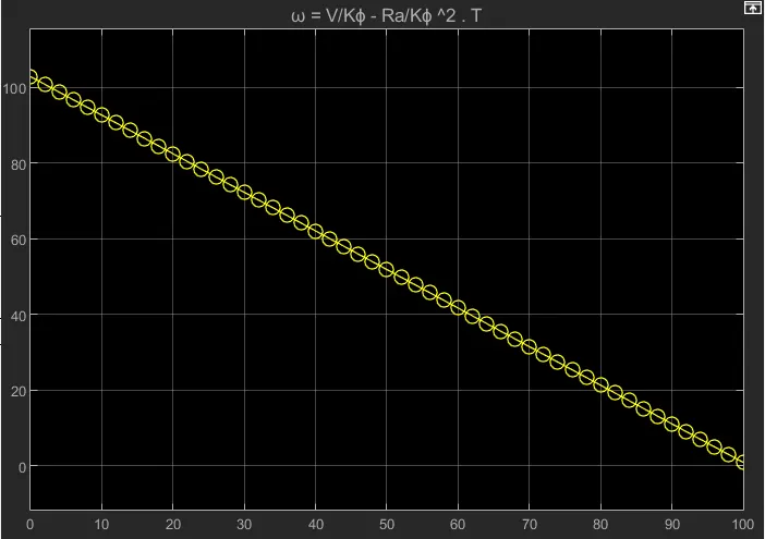
The above is the simulation result of the speed vs torque observed in scope.
4. Refer to the blog on below topic:
Induction Versus DC brushless motors by Wally Rippel, Tesla
Explain in brief about author’s perspective.
According to the blog by Wally Rippel, Principal power electronics engineer, he highlights the merits and demerits, working principle and similarities of DC brushless motor and Induction motor as a comparitive study and their roles to play in HEV application in near future.
Brushless DC motors:
Here, the author explains the construction of the motor in which rotor includes two or more permanent magnets that generate a DC magnetic field which enters the stator core and interacts with currents flowing within the windings to produce a torque interaction between the rotor and stator.
Inorder to provide constant torque, the magnitude and polarity of stator currents should be varied continuously by inverter.
3 phase induction motor:
The author explains the similarites of the stator construction between the Brushless DC motors and 3 phase induction motor and also explains how the rotor of the induction motor differs from the brushless DC motor. In DC induction motor, an induced voltage exists across the shorted structure that is proportionate to this speed difference between the rotor and electrical frequency. In response to this voltage, currents are produced within the rotor conductors that are approximately proportionate to the voltage, hence the speed difference. These currents interact with the original magnetic field to produce forces and thus torque.
Advantages of 3 phase induction motor over DC brushless motor:
Then, author explains the merits of using induction motors over DC brushless.
- Under 3-phase power, torque is produced at the outset. The motor has the ability to start under load.
- No inverter is needed whereas DC motor produces no starting torque without inverter when directly connected to fixed frequency utility power.
Limitations of 3 phase induction motor over DC brushless motor:
- They cannot operate from DC; AC is a must.
- When used with utility power, they are constant speed machines.
- When operated from utility power, they have limited starting torque and somewhat limited running peak torque capabilities, when compared to DC type machines.
Steps to overcome drawbacks of Induction motors:
Author lists some points here to overcome those drawbacks in induction motors to compete with DC brushless motor.
- By adding an inverter, it is possible to operate at variable speed from battery or other DC source by adjusting inverter frequency.
- By adding some feedback loops such that the inverter produces the exact frequency that the motor desires and torque performance can be achieved.
Similarities and differences:
Author explains the similarities and differences of both the motors and comparitive study is made.
- Both DC brushless and induction drives use motors having similar stators.
- Both drives use 3-phase modulating inverters.
- The only differences are the rotors and the inverter controls.
Difference in sensors: DC brushless drives require an absolute position sensor, while induction drives require only a speed sensor.
Peak point energy efficiency: DC brushless drive can also operate at unity power factor, whereas the best power factor for the induction drive is about 85 percent which is lesser than DC.
Controlling magnetic field induction: In brushless drive, the strength of the magnetic field produced by the permanent magnets is cannot be adjusted easily whereas in induction drives there is no permanent magnet and can be adjusted easily by varying the voltage supply to the inverter thus increasing average efficiency.
Cost: Permanent magnets are expensive also difficult to handle due to very large forces. This means that induction motors will likely retain a cost advantage over PM machines.
Motor control: Induction machines are more difficult to control. Achieving stability over the entire torque-speed range and over temperature is more difficult with induction than with DC brushless.
Conclusion of the author:
- The author comes to a conclusion that DC brushless drives will likely continue to dominate in the hybrid and coming plug-in hybrid markets, and that induction drives will likely maintain dominance for the high-performance pure electrics.
- Finally, he highlights the point that in future, we will see induction and DC brushless live and work side by side during the coming golden era of hybrid and electric vehicles since most of the hardware is common for both drives.
CONCLUSION:
- The types of power converter circuits are employed in electric and hybrid electric vehicle are explained.
- The EV steady state speed if duty cycle is 70% for the following Electric Vehicle's powertrain with 72V battery pack in shown in the diagram is found to be 38.6 r/s or 369 rpm.
- The mathematical model of a DC Motor for the below equation using Simulink is modelled.
ω = V/Kϕ -(Ra/(Kϕ^2)) .T - The blog on Induction vs DC brushless motor by author Wally Ripple is explained in brief.