Week-6 Challenge: EV Drivetrain
1. Which types of power converter circuits are employed in electric and hybrid electric vehicle?
Power Converters:
It is the process and control the flow of electric energy by supplying the voltage and currents in a form that is optimally suited for user loads.It will provide as much we required to perforn that specific task other left amount of energy is not wasted as the earlier one because it has power converters by using switching technique.
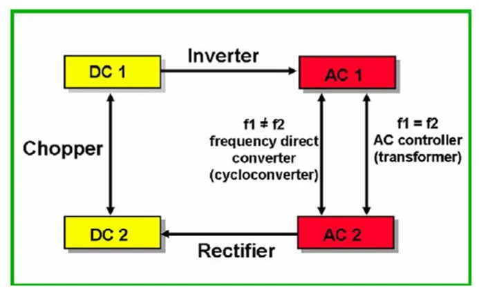
There are three types of Power Converter circuit are used in electric vehicles and hybrid electrical vehicles::
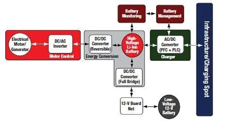
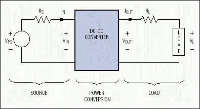
From the above figure we can see typically used three types of power converters.
They are DC-AC converters(inverters),AC-DC converters(Rectifiers) andDC-DC converters(choppers) with battery and motor.
AC motors also used in HEV and EV for traction of power and they again fed by the inverter and then again it is fed to the DC-DC and it is connected to the battery pack.
Function of Power Converters:
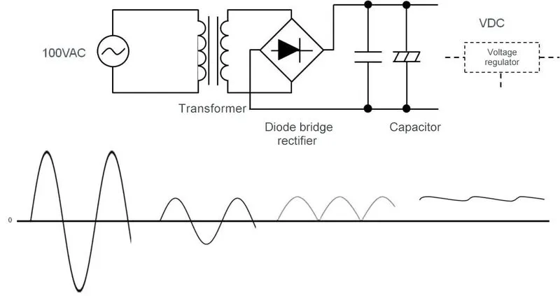
1.AC-DC converter:
It converts from AC electric power into DC electric power.It takes AC supply and gives DC output i.e Rectifiers.In this case the EV charger comes i.e battery charging applications.Most low power rectifiers are used domestic purpose that are in the single phase.3 phase is used in industrial applications...here the battery of the vehicle works on DC supply.The utility provides AC supply and thus to charge the battery of vehicles.The electrical network operates on AC supply and the battery is in DC nature.
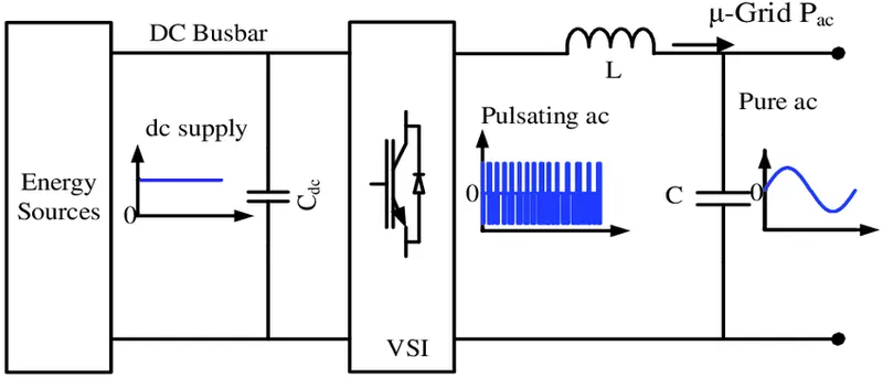
2.DC-AC converters:
In electrical vehicle typically used 3 phase induction motors.They are generally used in motor drives of EV and HEVThis inverter can changes the speed at which the motor rotates by adjusting the frequency of alternating current.This motor requires AC supply to run at the required speed which converts the DC power to AC power required by the 3 phase induction motors.It also performs function of recharging the batteries by regenerative brakings in HEV.This generally use power semiconductor switches such as MOSFET,IGBT..The output obtained from this is alternative square wave in nature.We can obtain sinusoidal waveform by using the various technologies.i.e modulation techniques and control strategies.
3.DC-DC converters:
In this converter,it converts one level of DC supply of voltage to other level of DC supply of voltage to which wr required to perform the specific task by storing the input energy temporary and obtaining the output at a different level of voltage.The stored energy is in the form of magnetic field components such as inductors,transformers...electric field in the capacitors..It used to interface the electric elements in the power train by choppers.
If we want to increase the battery voltage level then we use step up converter DC-DC.
If we want to decrease the battery voltage level then we use step down converter DC-DC.
Conclusion:
We saw all the three types of Power converters and their description.
2. In Electric Vehicle's powertrain with 72V battery pack in shown in the diagram below. The duty ratio for acceleration operation is 'd1' and for the braking operation the duty ratio is 'd2'.
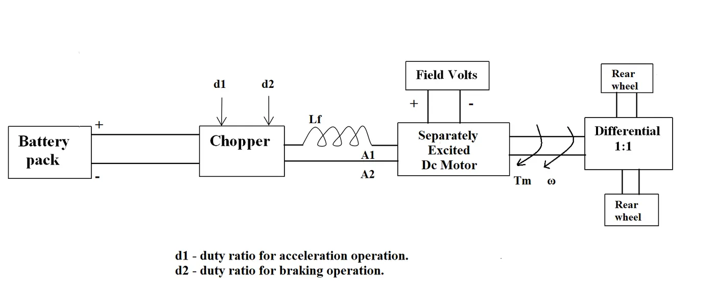
The other parameters of the electric vehicle is given below,
Motor and Controller Parameters:
Rated Armature voltage= 72 V
Rated armature current= 400 A
Ra= 0.5Ω, KΦ= 0.7 Volt second
Chopper Switching frequency= 400 Hz
The vehicle speed-torque characteristics are given by the below equation

What is EV steady state speed if duty cycle is 70%?
Given,
Duty cycle=70%
Voltage=Rated Armature Voltage*Duty cycle
=72*0.7=50.4V
The equation of the Torque speed characteristics of DC motor is given by
Tm=((V*K `phi`)/Ra-(K`phi` )^2/Ra)*`omega`
Where,Tm is the torque motor Voltage
V is Voltage,Ra is armature Resistance
K`phi`is motor constant
`omega`is angular speed
From the given values of data substituting in the Tm equation
Tm=(((V*K `phi`)/Ra)-((K`phi` )^2/Ra))*`omega`
Tm=((72*0.7)/0.5-(0.7)^2/0.5)*`omega`
Tm=(35.28/0.5)-(0.98)*`omega`
Tm=(70.56)-(0.98*`omega`) -----equation1
Tv=24.7+((0.0051)*(`omega`)^2) -----equation2
equating both the equation 1 and 2 we get
24.7+((0.0051)*(`omega`)^2)=(70.56)-(0.98*`omega`)
(0.0051*(`omega`)^2)+(0.98*`omega`) -45.86=0
This above equation is in the form of quadratic equation is
ax^2+bx+c=0
x=((-b)`+-`((`square root`((b^2)-4ac))/(2*a))
From comparing the equation values we know
a=0.0051,b=0.98,c=-45.86
substituting in the quadratic equation we get
x=(-0.98`+-``square root`((0.98)^2-((4*0.0051)(-45.86)))/(2*0.0051))
we get `omega`=38.92 rad/sec
`omega`=-231.07rad/sec
Conclusion:
Steady state of the angular speed is 38.92 rad/sec,if the duty cycle is 70% when the speed value is negative then the torque is transferred to the motor externally when the speed value is positive then the steady state of the motor generated torque reaches the wheel.
3. Develop a mathematical model of a DC Motor for the below equation using Simulink.
ω">ω=V/Kϕ">ϕ -Ra/Kϕ">ϕ^2 .T
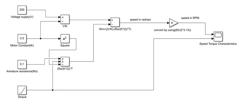
After preparing the model enter the K value

To enter the K value, enter it and save it in the script file then run it by using evaluate section

Then it will store in the workspace as shown above.
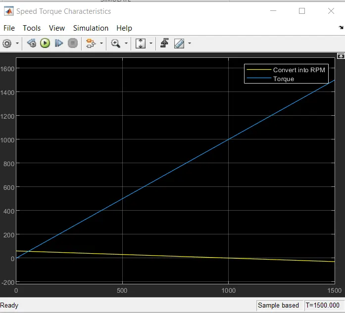
We took the simulation time as 1500sec.
Conclusion:
From the output we can see as the torque goes on increasing speed of the motor will decrease.
4.Refer to the blog on below topic:
Induction Versus DC brushless motors by Wally Rippel, Tesla
Explain in brief about author’s perspective.
From the study of the above reference by Wally Rippel explained difference betweeen the induction motor and DC brushless motor used in pure electric vehicle and hybrid electric vehicle.
The author described by comparing the performances,merits, demrits,structure and prices of the components which are used in both Pure electric vehicle and hybrid electrical vehicle.
The EV drives also has different types of motor and drive train according to our requirements.Since it is very difficult to predict the future of current technology.Both the induction motor and DC brushless motor has their individual capabilities on their own.
From the authors description we have to concentrate on the uses of this two motors but we should not consider which one is best.The two motors i.e induction motors and DC brushless motor have some similarities in the hardware like stators and 3 phase modulating inverters.But the difference is in the rotor and the inverter controllers,since they thy have only small minor difference between the two motors.
After all the comparision between the two motors he came to conclusion plugin hybrid electric vehicle and hybrid electrtic vehicle will dominant than th einduction motors and DC brushless motors will both drive the high performance pure electrics so in the coming golden era of pure hybrid electric vehicle.It also becomes true.
Advantages of DC brushless motor over induction motor
Rotor generates less heat in the DC brushless motor.
It will not produce Starting torque when directly connected to the fixed frequency utility power it seems to have an inverter.
Rotor cooling is easier and when higher the efficiency for this driver.
It can operate at a unit power factor where as in induction motor it is above 85%
The higher enegry efficiency in the DC brushless drive will have a few high % points than the induction motors.
The magnetic field is produced by the permanent magnets will be adjustable.We cannt change this effect of magnetic field with permanent magnet.
Induction motors are more difficult to control as the control laws are more complex.
Advantages of Induction motors over the DC brushless motors:
They can also operate from DC but AC must be there.
When from utility power they can operate at a limited starting torque and it has limiter running torque capabilities.
So torque performances is low when compared to DC machines.
Induction motors have no magnets but it can adjustable magnetic fields.
At the low loads inverter can reduce the voltage so magnetic losses are reduced and which increases the efficiency.
Magnetic and conduction losses can be trade as such that efficiency is optimised.
Magnetic losses increse proportionality and part load efficiency decreases as the machine size grows in the DC machine.
In the induction motor as the machine size grows,losses do not increases gradually so drive performances is acheived.
Average efficiency is acheived upto some extent.
Permanent magnets are most expensive and rotors also difficult to handle because they are very large forces.
Conclusions:
After all the comparision between the two motors he came to conclusion plugin hybrid electric vehicle and hybrid electrtic vehicle will dominant than th einduction motors and DC brushless motors will both drive the high performance pure electrics so in the coming golden era of pure hybrid electric vehicle.It also becomes true.