Week-6 Challenge: EV Drivetrain
Study 1:
Objective:Types of power converter circuits employed in electric and hybrid electric vehicle
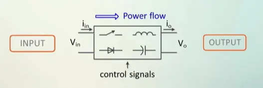
Power electronic converters:It is an electronic device made up of high power semiconductor switches that uses different switching state to change the magnitude and waveform of the voltage and current between the input and output.
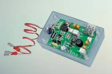
High Power semiconductor switches
Types of Power converters:
- Diode rectifier
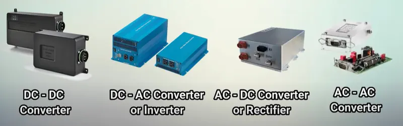
- DC to DC Converter (DC Chopper)
- DC to AC Converter (Inverter)
- AC to DC Converter (Controlled Rectifier)
- AC to AC Converter (AC voltage regulator)
- Static Switches
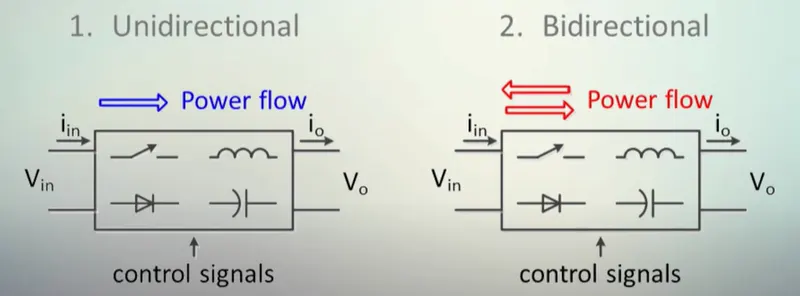
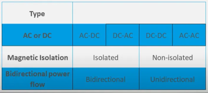
Power converters are classified as Unidirectional and Bi-directional power flow.
Unidirectional: It uses diodes at the output in order to allow the power flow in one direction only.
Bi-directional:Semi conductor switches like mosfet or IGBT'S are used on both input and output sides
Power converters are classified by Transformer Isolation between input and output:
Insulation in power converters is primarily required for safety reasons.
Power converters in EV and HEV:
Due to the automotive constraints, the power converter structure has to be reliable, lightweight, small volume, with high efficiency, low electromagnetic interference and low current/voltage ripple.
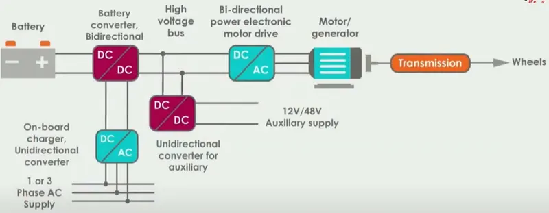
An electric car uses a central DC bus called High voltage Bus in fig. for exchanging powers between the various electric components and the converters are responsible for controlling the power flows.
- The on-board chargers are responsible for converting the AC power from the grid on the central DC bus for charging the traction batteries.Hence it is an AC to DC converter.
- Now battery converter controls the charging for discharging the traction batteries by either drawing or feeding power from high voltage bus. Hence Battery converter is a Bidirectional DC-DC converter.
- Similarly the Auxillary Battery converter is used to charge the auxillary battery by drawing power from High voltage DC bus.
- Finally the motor drive is a DC-AC inverter used to control and operate AC Motor.It is a bi directional and feeds power to Motor for propulsion and acts as an AC-DC rectifier by drawing power from Motor during regenerative braking.
- In some cases a Motor drive can be DC-DC converter if the motor is a DC motor like brushless DC motor.
| Converter | AC or DC | Isolation | Direction |
| On-board charger | AC-DC | Isolated | unidirectional |
| Batter converter | DC-DC | Isolated | Bidirectional |
| Motor Drive | DC-AC | Isolated/non isolated | Bidirectional |
| Auxilary Battery converter | DC-DC | Isolated/non isolated | unidirectional |
Study2:
Objective:To find the Ev steady state speed if the duty cycle is 70%
Inputs:
Rated Armature voltage= 72 V
Rated armature current= 400 A
Ra= 0.5Ω,
KΦ= 0.7 Volt second
Chopper Switching frequency= 400 Hz
The vehicle speed-torque characteristics are given by the below equation
Tv=24.7+(0.0051)w^2
The motor speed- torque characteristics are given by the below equation
w=v/kϕ - Ra/kϕ^2 .T
w= 72*0.7/0.7-0.5/(0.7)^2 * T
w= 72-1.02*T
where Tv =T; Substituting Tv in above equation
w=72-1.02(24.7+(0.0051)w^2)
w=46.806-0.0052w^2
0.0052w^2+w-46.806=0
Finding the roots of the equation
ws = 38.85 rad/sec ; -237.227 rad/s
coverting to rpm
N =371 rpm
Study 3 :
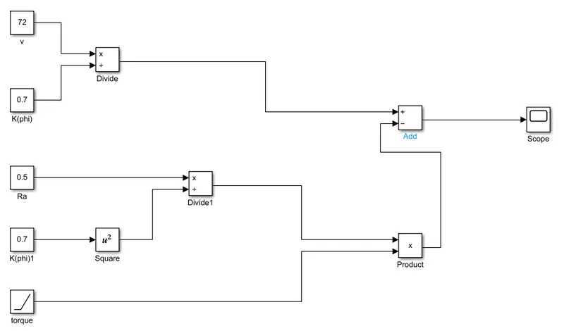
Objective: To develop a mathematical model of a DC Motor for the below equation using Simulink.
w=v/kϕ - Ra/kϕ^2 .T
Following are the blocks used to develop mathematical model.
Constant : Using this block , input value is provided to the Voltage V, Ra & kϕ .
Ramp : It provide torque values.
Square:For squaring the kϕ value
Divide , add , product : These blocks are used as required for the equation.
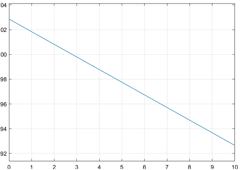
Scope : Represent the graph of torque speed
Study 4:
Objective:The author 'Wally Rippel' brief's about induction versus DC Brushless motors.
In the inital stages there were lead acid batteries, DC brush motors, and contactor controllers. Today, none of these remain .Lead has been replaced by Lithium and DC by either DC brushless and induction.
DC brushless motors:
With brushless machines, the rotor includes two or more permanent magnets that generate a DC magnetic field (as seen from the vantage point of the rotor). In turn, this magnetic field enters the stator core (a core made up of thin, stacked laminations) and interacts with currents flowing within the windings to produce a torque interaction between the rotor and stator. As the rotor rotates, it is necessary that the magnitude and polarity of the stator currents be continuously varied – and in just the right way - such that the torque remains constant and the conversion of electrical to mechanical energy is optimally efficient. The device that provides this current control is called an Inverter. Without it, brushless motors are useless motors.
Induction motors:
A forerunner of the 3phase Induction motor was invented by Nikola Tesla sometime before 1889. Curiously, the stators for the 3-phase induction motor and the DC brushless motor are virtually identical. Both have three sets of “distributed windings” that are inserted within the stator core. The essential difference between the two machines is with the rotor.Unlike the DC brushless rotor, the induction rotor has no magnets – just stacked steel laminations with buried peripheral conductors that form a “shorted structure.” .
| Brushless Motors | Induction |
| Inverter is required for current control | For 3 phase induction motor no inverter is required |
| A brushless DC motor produces no starting torque when directly connected to fixed frequency utility power. | 3-phase induction motor is connected to utility type 3-phase power, torque is produced at the outset; the motor has the ability to start under load |
| DC supply | AC supply |
| DC brushless drives require an absolute position sensor | while induction drives require only a speed sensor |
| Less rotor heat is generated with the DC brushless drive. Rotor cooling is easier and power factor is upto 100% for this derive | Rotor cooling is difficult and peak point efficiency is 85% |
| With DC brushless, as machine size grows, the magnetic losses increase proportionately and part load efficiency drops. | With induction, as machine size grows, losses do not necessarily grow. |
| Permanent magnets are expensive. Permanent magnet (PM) rotors are also difficult to handle due to very large forces | Inverter ratings and costs appear to be lower, especially for high performance drives.and also more dfificult to control. |
Both motors have their own limitations. DC burshless motors are preferred for Hybrid and Plug HEV whereas induction motors are preferred for Electric cars.