Week-6 Challenge: EV Drivetrain
1. Which types of power converter circuits are employed in an electric and hybrid electric vehicle?
Power electronic technology deals with processing and controlling the flow of electrical energy to supply voltages and currents in a form that is optimally suited for the end user’s requirements coming to the Automobile industry the following types of the power converter are used
- AC to DC = Rectifier: It converts AC to unipolar (DC) current
- DC to AC = Inverter: It converts DC to AC of desired frequency and voltage
- DC to DC = Chopper: It converts constant to variable DC or variable DC to constant DC
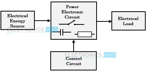
The block diagram shows the entire cycle of the power converter where one type of Energy source is converted into another form of energy with the help of power electronic circuits that have been explained below.
AC to DC Converters or Rectifiers
The conversion of AC supply to DC is also called Rectification this type of power circuit are widely used in both EV and HEV applications like charging of Batteries, the main components used for this rectification process are transformer, switching unit, filter and finally the required DC output the below image shows the conversion of 230V AC to 5V DC
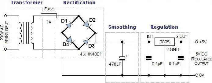
these rectifiers are further divided into two types
- Uncontrolled rectifiers
- controlled rectifiers
- Uncontrolled rectifiers :
This type of rectifier converts AC voltage mains from fixed DC voltage since the diodes are uncontrollable components these converts are called uncontrollable rectifiers with a fixed voltage the input supply can be either single-phase or three-phase
- controlled rectifiers :
This type of converter is similar to uncontrolled rectifiers but the difference is that these uncontrolled rectifiers are replaced by a controlled thyristors family of devices such as SCR
These are also called phase controlled rectifiers. Unlike diodes, thyristors can be controlled by triggering them at desired instants to vary the output voltage.
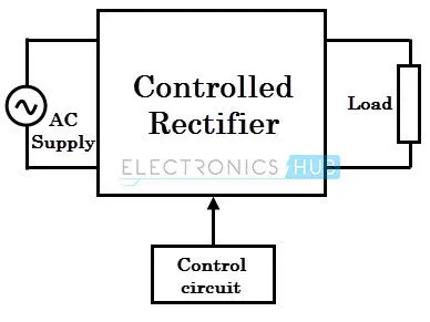
The block diagram of a controlled rectifier is shown in the above figure that transfers the DC power to the load in a controlled manner by varying the triggering angle of thyristors using different technologies such as a microprocessor or microcontroller-based techniques.
DC to DC Converters
This type of DC-DC converter is used in many applications like the automobile industry where it requires converting one level of DC voltage to Another level of DC which can be used for vehicle control circuits and infotainment systems
A DC chopper is a static device that converts a fixed input DC voltage to variable DC output or a fixed DC output of a different magnitude than the input value. The block diagram of a DC chopper is shown in the figure below.
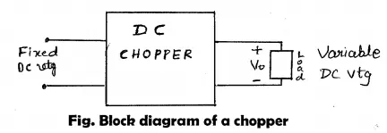
The chopper circuit is connected between the DC input source and DC load. This chopper consists of power electronic switching devices such as thyristors connected so that they produce the required DC voltage to the load.
The output voltage is controlled by adjusting the ON time of the thyristor which in turn changes the width of the DC voltage pulse at the output. This method of switching is called pulse width modulation (PWM) control.
DC choppers are classified into three basic types based on input and output voltage levels and are discussed below.
- Step-down Chopper or Buck converter :
A step-down chopper produces an average output voltage lower than the input DC voltage. The circuit for this converter is shown in the figure below.

Here the switching component is a thyristor that switches the input voltage to the load when it is triggered at particular instants. A diode acts as a freewheeling diode that allows the load current to flow through it when the thyristor is turned OFF. If this diode is absent, a high induced EMF in inductance may cause damage to the switching device.
The average output voltage of the converter is varied by controlling the turn ON/OFF periods of the thyristor. When the thyristor is turned ON, the output voltage is the same as the input voltage and if it is turned OFF, the output voltage is zero.
The output voltage is equal to (TON / T) Vin. So, by controlling the duty ratio K = (TON / T), the output voltage will be increased.
2.Step-up Chopper or Boost converter :
In this chopper, the output voltage is always greater than the input voltage. The configuration of a boost converter is shown in the figure below.
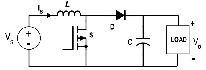
Here also a switch is used, which is connected in parallel with the load. This switch is a thyristor or an SCR.
As similar to the buck converter, a diode is placed in series with the load that allows the load current to flow when the thyristor is turned OFF When the thyristor is turned ON, the diode is reverse-biased and hence it isolates the load circuit from the source. So the inductor charges to the maximum input voltage source. When the thyristor is turned OFF, the load gets the voltage from the input as well as from the inductor. So the voltage appearing across the converter output will be more than the input.
Here the output voltage is equal to (1/ 1 – d) times the input voltage, where d is the duty ratio (TON / T). By varying this duty ratio, the output voltage will be varied till the load gets desired voltage
3.Buck/Boost converter :
This chopper can be used both in step-down and step-up modes by continuously adjusting its duty cycle. The buck-boost converter configuration is shown in the figure below that consists of only one switching device, i.e., one thyristor. Along with an inductor and diode, the additional capacitor is connected in parallel with this circuit.

When the thyristor is turned ON, the supply current flows to the inductor through the thyristor and induces the voltage in an inductor. When the thyristor is OFF, the current in the inductor tends to decrease with the induced emf reversing polarity. The output voltage of this converter remains constant as the capacitor is connected across the load. By varying the value of duty ratio to a certain value, the output voltage is lower than the input voltage, typically in the range 0 ≥ k > 0.5, thus a buck converter. And the output is higher than the input voltage if the duty ratio is in the range of 0.5 > K ≥ 1, thus acts as a boost converter.
DC to AC Converters or Inverters
These converters are connected between the DC source of fixed input and variable AC load. Most commonly, these DC to AC converters is called inverters. An inverter is a static device that converts fixed DC supply voltage to variable AC voltage. These types of converters are used for AC traction motors used in pure EV which has shown below
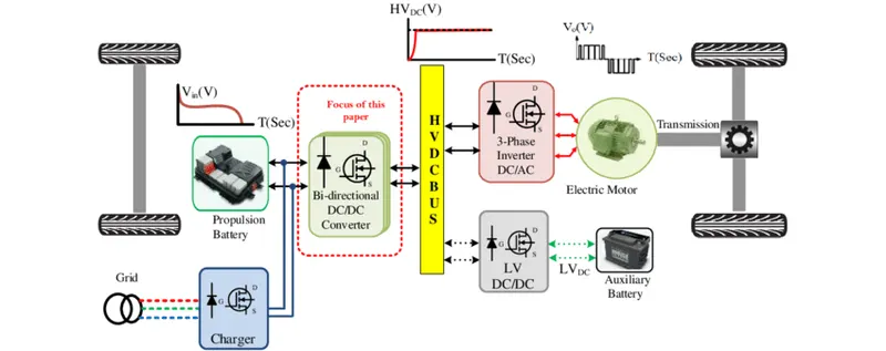
Here the fixed DC voltage is obtained from batteries or by DC link in most power electronic converters. The output of the inverter can be variable/ fixed AC voltage with variable/fixed frequency. This conversion from DC to AC along with variable supply is produced by varying the triggering angle to the thyristors. Most of the thyristors used in inverters are employed with the forced commutation technique. These can be single-phase or three-phase inverters depending on the supply voltage. These converters are mainly divided into two groups. One is PWM based inverters and the other multilevel inverters. Further, these are classified as voltage source inverter and current source inverter. Each type is subdivided into different types such as PWM, SVPWM, etc. Multilevel inverters are more popular in industrial applications.
The inverters overcome the drawbacks of PWM based inverters.
2. An Electric Vehicle's powertrain with a 72V battery pack is shown in the diagram below. The duty ratio for acceleration operation is 'd1' and for the braking operation the duty ratio is 'd2'.
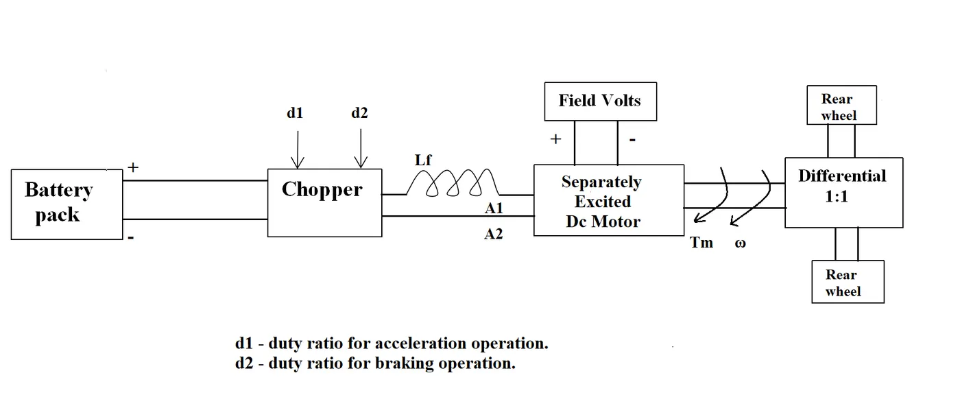
The other parameters of the electric vehicle are given below,
Motor and Controller Parameters:
Rated Armature voltage= 72 V
Rated armature current= 400 A
Ra= 0.5Ω, KΦ= 0.7 Volt second
Chopper Switching frequency= 400 Hz
The vehicle speed-torque characteristics are given by the below equation
 .......3
What is EV steady-state speed if the duty cycle is 70%?
The torque equation of the motor is given below
`t`=`((v-omega k phi) kphi) /(Ra)` ....... 1
where
t = torque of the motor
v = voltage of the motor
Ra = armature resistance
`Kphi` = motor constant
vehicle voltage = 72 * 0.72 = 50.4 V
substitute the the given values in the equation 1
`t = ((50.4 * 0.7 - (0.7 * 0.7)) /0.5) * omega`
`t = 70.56 - 0.98 *omega` ..... 2
Solving the equation 3 and 2 torque equations
`24.7 + 0.0051 omega^2 = 70.56 - 0.98 * omega`
`0.0051 omega^2 + 0.98 omega -45.86 = 0`
by solving the equation we can get the steady state speed of the vehicle for the duty cycle with 70%
`omega = 38.8 (rad) /sec`
`omega = -230 . 95(rad) / sec`
here we are considering the real part value `omega = 38.8 (rad) /sec`
3. Develop a mathematical model of a DC Motor for the below equation using Simulink.
ω= V/Kϕ -Ra/Kϕ^2 .T
The mathematical model of the DC motor for the above equation has been done using the above problem data given has been shown below
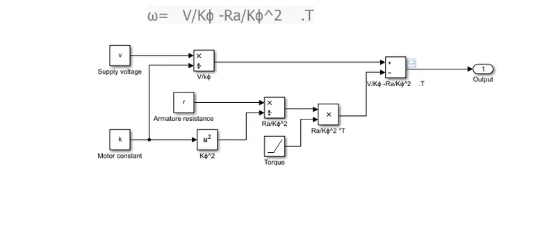
and the output speed of the model is shown below
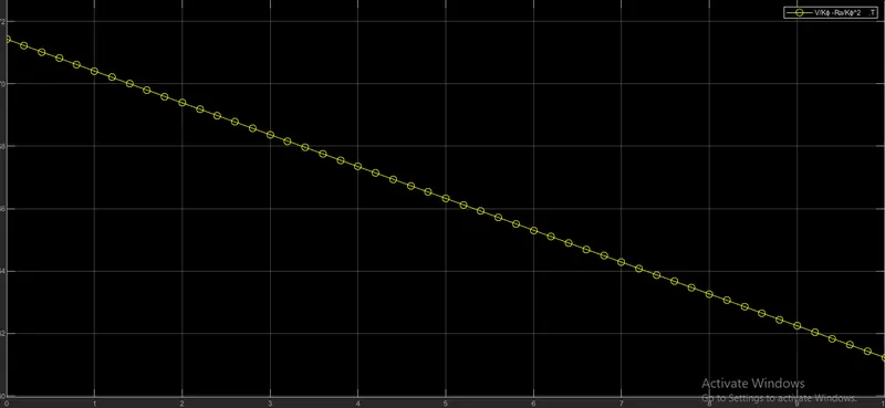
from the above plot, we can convey that with the increase in load torque there will be a decrease in speed
Induction VS DC Brushless Motors by Wally Ripple, Tesla
From the above study of Induction motor Vs DC Brushless motors by Wally Ripple, He explained the comparison of the two motors with past and present eras of usage in the EV domain with in-depth technical analysis like construction and efficiency then Wally Ripple finally conclude that DC brushless drives will likely continue to dominate in the hybrid and coming plug-in hybrid markets, and that induction drives will likely maintain dominance for the high-performance pure electrics but this two will also work side by side in coming generations