Week-6 Challenge: EV Drivetrain
1) Types of power converters used in Electric and Hybrid Electric Vehicle:
Electric Vehicle and Plug in Hybrid electric vehicle:
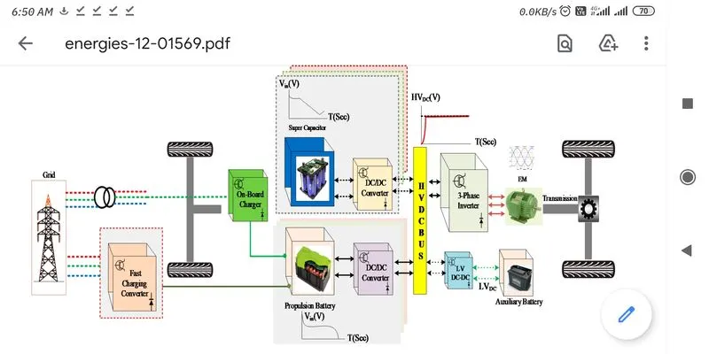
Power Convertors used:
- AC/DC Converter
- DC/AC Inverter
- DC/DC Step up Converter
- DC/DC Step down Converter
Description:
AC/DC Converter:
- This type of converter is used in On Board Charger (OBC) and in Fast charging Station converter.
- This is a rectifier circuit which is used to convert the alternating AC voltage supply to the Dc voltage.
- This is mainly used because there is no readily available DC Voltage station.
- Usually the grids are operating in High voltage AC.
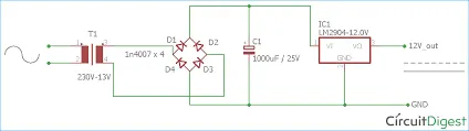
- The OBC consists of Step down Transformer, Input filter circuit, rectifier circuit and the linear voltage circuit.
- The step down transformer is used to reduce the voltage from the 230V AC to required Voltage of 120V AC or 240V AC.
- Then Isolator, surge protector and to the input filter circuit for the protection of the device.
- Then the AC voltage is fed to rectifier circuit. It is the diode bridge full wave rectifier circuit and amplifier is also used to boost the voltage by meeting the losses.
- The Output of rectifier circuit is DC of required voltage corresponding to the input AC voltage to the rectifier circuit.
- Then this voltage is used for charging the Battery of the vehicle.
DC to AC Inverter:
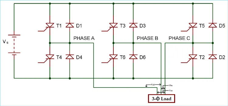
- Generally DC to 3 phase AC inverter is used.
- The inverter circuit consists of the filter (capacitor) in the input side and main bridge is 6 pairs of thyristor and diode.
- The thyristor T1 in On state is used to pass the positive half cycle and it is turned off and the reverse voltage is protected by diode.
- The thyristor T2 in Off state is used to pass negative half cycle and it is turned off and reverse voltage is protected by diode.
- Hence the one cycle is produced.
- The Thyristor T3,T4,T5 and T6 are switched On and OFF by controlling the gate supply to produce the ac voltage cycle with 120degree phase difference.
- The Gate supply is produced by the Phase regulator.
- This process is repeated to produce the 3phase AC supply corresponding to the Dc supply.
- Then this Voltage is directly applied to the 3 phase load Or this voltage is stepped by the step up transformer an then supplied to 3 phase load.
- The three phase supply used in the electrical vehicle is the Induction Motor (traction motor).
DC to Dc Converter:
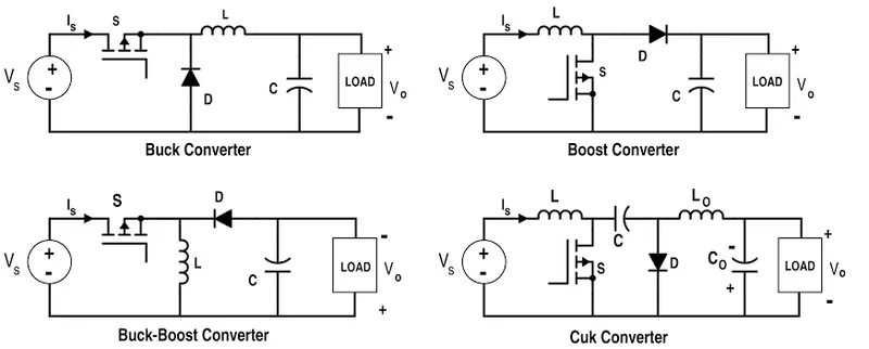
- DC to DC converters are of Buck converter, boost converter, Buck-Boost converter and Cuk converter
- Buck converter is used to reduce the DC of high voltage to low voltage.
- Boost Converter is used to increase the DC of low voltage to High voltage.
- Buck Boost is used for both step up and step down of DC voltage and is more efficient because of using less components.
- Cuk is used to reduce the ripples and noises from the Converter.
2) Calculation the EV steady state Speed:
Objective:
To calculate the EV steady state speed if the duty cycle is 70%.
Given:
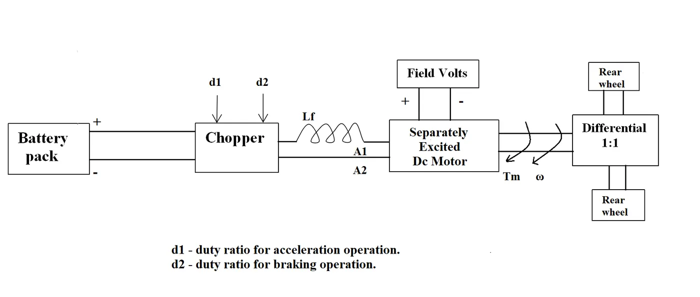
Battery pack Voltage = 72V
Rated armature voltage = 72V
Rated armature current = 400A
Armature resistance = 0.5
Kφ = 0.7
Chopper frequency = 400Hz
duty cycle = 70%
Torque-speed characteristic equation is given by,
Tv = 24.7 + 0.0051w^2
Tm:Tv = 1:1
Calculation:
Average Voltage at 70% duty cycle= 0.7*72 = 50.4
w = (V/Kφ)-(Ra/Kφ^2)*Tm
w= (50.4/0.7) – (0.5/0.7^2)*Tm
w=72 – 1.0204 Tm
Tm= 70.5605-0.98w
Tv = Tm
24.7 + 0.0051w^2 = 70.5605 – 0.98w
0.0051w^2 + 0.98w – 45.8605 =0
By solving this quadratic equation,
w= 38.915 and -231.072
Hence w = 38.915 rad/sec
Speed at rpm = 38.915*60/(2*3.14) = 371.79
Therefore Speed in rpm = 371 rpm
Result:
EV Steady state speed = 371 rpm.
3) Mathematical model of DC motor:
Objective:
To develop a mathematical model of a DC motor for the below equation using Simulink.
w = V/Kφ – (Ra/Kφ^2)*T
Blocks Used:
- Constant
- Ramp
- Add
- Divide
- Product
- Square (math function)
- XY graph
Model:
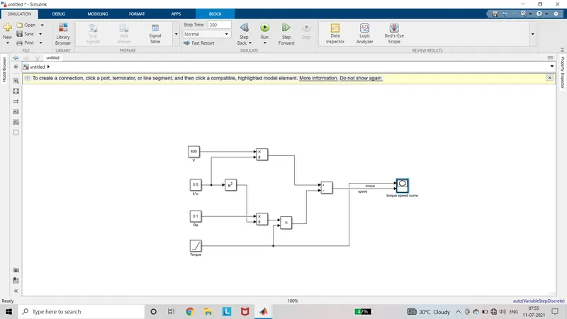
Procedure:
- Add the required blocks to the model.
- Connect the blocks as required for the model.
- For Voltage V the constant input of 400 is given
- Kφ is the constant input 0.7
- Ra is the constant resistance value of 0.5
- Torque is given as the constant ramp input.
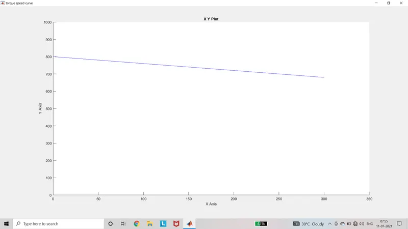
- Torque value is given to the X axis of XY graph
- Speed value is given to the Y axis of XY graph
- Run the model for 300 seconds.
Output:
Result:
The mathematical model of the given equation using Simulink is developed and the torque speed characteristics is plotted in the output.
4) Induction Vs DC Brushless motor by Wally Rippel,Tesla:
Objective:
To study about the Induction Vs DC Brushless motor by Wally Rippel,Tesla.
Observation:
In this Blog Wally Rippel, Tesla discussed about the various types of motor that he came across from 1960s. Back then the motor used in the electrical vehicle is brushed DC motor with contactor which is no more in use in this field. Nowadays it is replaced with Brushless DC motor and 3phase induction motor. By using the contactors and brushed DC motor the losses are high.
In both brushless DC motor and 3 phase induction motor, the stator is same. Only difference is the type of rotor used. In the brushless Dc motor, the rotor is made of the two or more permanent magnet. This permanent magnet produces the magnetic field which comes in contact with the stator windings. When the supply is given to the stator, the torque is produced in the rotor which makes the motor run. To maintain the torque constant, the current should be varied continuously. So that inverter is used. This type of motor performs well at peak speed. The torque values can be varied by changing the value of B. But It is not possible to change the value of B in permanent magnet.
Here comes the induction motor which was invented by the Nikola Tesla. The stator is same as we discussed before but the rotor is made of laminated steels and the conductors are arranged in the slot. When the supply is given to the Stator, it produces rotating magnetic field. This comes in contact with the rotor. The frequency of the rmf is equal to the frequency of the supply. So that Voltage is induced in the Rotor and value is equal to difference between the value of supply frequency and speed of rotor itself. The ends of rotor are short circuited by the end rings, so the current flows through the rotor. Due to effect of rmf, the torque is produced in the rotor.
Hence the 3 phase motor is run directly from the utility power source. But the limitation is it runs on line voltage but not on DC voltage. Hence the inverter is added to the circuit. By using the switching operations in the Inverter the speed can be varied. And the value of B also can be reduced because there is no permanent magnet.
The brushless DC motor operation at the peak performance is efficient. The induction motor may be of less efficient at peak. But average efficiency of the induction motor is better than the brushless DC motor.
Result:
The Brushless DC motor is used for Hybrid and Plug in hybrid vehicle. While the induction motor is used for pure electric vehicle.