Week-6 Challenge: EV Drivetrain
1. The objective is to list and explain which types of power converter circuits are employed in electric and hybrid electric vehicles.
The Power Converters used in electric and hybrid electric vehicles play a vital role in distributing the power to the drivetrain of the vehicle. Since these type of vehicles worKs with a high scale of power, advanced types of power converter circuits are been used. There are certain converter circuits used in Ev ad Hybrid Vehicles namely,
- AC / DC Converter
- DC / AC Converter
- DC / DC Converter
AC /DC Converter
- This Converter is used as an On-Board charger in Plug-in vehicles. The power fed to the converter circuit is in the form of an alternating current. The battery needs to be charged with a Direct Current Source. So this converter is used to convert the AC supply o DC in Hev and EVs.
DC / AC Converter
- In most o Vehicles, an AC motor is used and it requires an AC power source for worKΦing. The DC power stored in the battery is fed to the motor after the conversion of DC to AC supply by an inverter circuit.
DC / DC Converter
- This type of converter is used to boost or chop the DC voltage level. This converter circuit can be used to distribute the required voltage level fr each component in the vehicle. Most DC-to-DC converters are designed to move power in only one direction, from dedicated input to output. A bidirectional converter is useful, for example, in applications requiring Regenerative BraKing of vehicles, where power is supplied to the wheels while driving, but supplied by the wheels when braKΦing.
2. The objective is to find EV steady-state speed if the duty cycle is 70%.
- An Electric Vehicle's powertrain with a 72V battery pack
- The duty ratio for acceleration operation is 'd1' and for the braKΦing operation the duty ratio is 'd2'.
Given data,
Rated Armature voltage= 72 V
Rated armature current= 400 A
Ra= 0.5Ω, KΦ= 0.7 Volt second
Chopper Switching frequency= 400 Hz
- The vehicle speed-torque characteristics are given by the below equation

- Firstly, we need to figure out the output voltage
V= V (Battery) * Duty cycle
V = 72 * 0.70
V = 50.4V
The output voltage is 50.4 V.
- Then, calculate the Vehicle Torque
T = (V - ωKΦ) * (KΦ/Ra)
where,
V = Output Voltage
ω = Steady Speed of the motor
KΦ = Motor Constant
Ra = Armature resistance
T = (50.4 - 0.7ω) * (0.7/0.5)
T = (35.28 - 0.49ω)/0.5
T = 70.56 - 0.98 ω
The given vehicle torque is,
Equating the two values of Vehuice Torque,
70.56 - 0.98ω = 24.7 + 0.0051 ω^2
70.56 - 24.7 = 0.0051 ω^2 + 0.98 ω
46.94 = 0.0051ω^2 + 0.98 ω
By rearranging the equation,
0.0051ω^2 + 0.98ω - 46.94 = 0
By quating the quadratic equation, we get,
ω1 = 39.697 and ω2 = -231.85
Let's consider the positive value, so the steady-state speed is 39.697 rad/sec.
3. The objective is to develop a mathematical model of a DC Motor for the below equation using Simulink.
ω= V/Kϕ -Ra/Kϕ^2 .T
The values for a set for these parameters in the Simulink Model are,
- V = 72
- Kϕ = 0.7
- Ra = 0.5
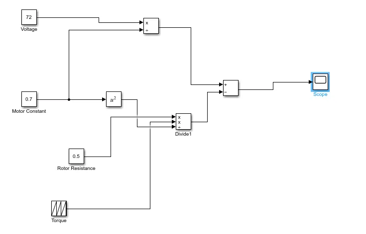
- This model is simulated to obtain the results for Toque Vs Speed Characteristics.
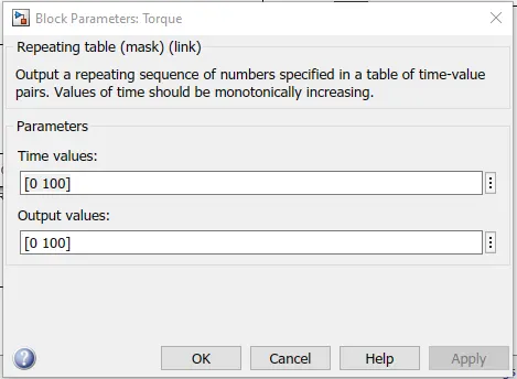
- The Repeating Sequence block is used to feed the Torque value signal. We can specify any waveform, using the block dialog's Time values and Output values parameters.
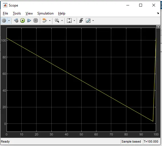
- This model specifies a sawtooth waveform of speed that repeats every
100seconds from the start of the simulation and has a maximum amplitude of 102 rad/sec and minimum amplitude of 2.9 rad/sec.
4. By Referring to the blog on the below topic:
Induction Versus DC brushless motors by Wally Rippel, Tesla
I acknowledge some of the salient points that are revolutionized over the years in the automotive industry and they are listed below,
- In the beginning, the author describes the dominance of IC engines in the earlier days of the automotive world. the engine and working procedure were the same as but the power figures were only changed.
- And the electric cars came into the picture with the idea of electric motors and battery packs.
- There were lead-acid batteries, DC brush motors, and contactor controllers. Today, none of these remain
- Lead has been replaced by Lithium and motors are upgraded over time.
- There are two types of motors discussed in this blog by the author and there can be distinguished as below,
| DC Brushless Motors | Induction Motors |
|
|
|
|
|
|
|
|
|
|
|
|
|
|
|
|
|
|
|
|
- The conclusion is that both are one on one efficient on certain points. The fact that so much of the hardware is common for both drives could mean that we will see induction and DC brushless live and work side by side during the coming golden era of hybrid and electric vehicles.