Week-6 Challenge: EV Drivetrain
Aim:
1) Which types of power converter circuits are employed in an electric and hybrid electric vehicle?
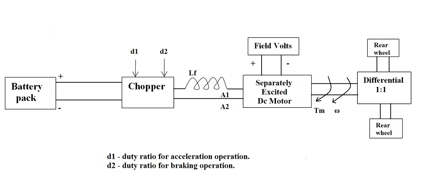
2) An Electric Vehicle's powertrain with a 72V battery pack is shown in the diagram below. The duty ratio for acceleration operation is 'd1' and for the braking operation the duty ratio is 'd2'.
The other parameters of the electric vehicle are given below,
Motor and Controller Parameters:
Rated Armature voltage= 72 V
Rated armature current= 400 A
Ra= 0.5Ω, KΦ= 0.7 Volt second
Chopper Switching frequency= 400 Hz
The vehicle speed-torque characteristics are given by the below equation

What is EV steady-state speed if the duty cycle is 70%?
3) Develop a mathematical model of a DC Motor for the below equation using Simulink.
`omega=v/(kphi)-(Ra)/(kphi)^2.T`
4) Refer to the blog on the below topic:
Induction Motor Versus Brushless DC Motors by Wally Rippel, Tesla
Explain in brief about author’s perspective.
Aim 1:
Which types of power converter circuits are employed in electric and hybrid electric vehicles?
The types of power converter circuits employed in electric and hybrid electric vehicles are:
- AC to DC Converter
- DC to AC Converter
- DC to DC Converter
AC to DC Converter:
- This converter takes in AC voltage and converts it into DC voltage.
- It is also known as a rectifier.
- The electrical network operates on an AC supply and the battery is of a DC nature. Hence, a rectifier is needed to convert the AC voltage to DC in order to store the energy in a battery.
DC to AC Converter:
- This converter takes in DC voltage and provides AC voltage at the output.
- It is also known as an inverter.
- It is used to transmit the voltage from a battery (DC supply) to an AC induction motor.
DC to DC Converter:
- This converter takes in DC voltage of one voltage level and frequency and converts it to another voltage level and frequency.
- It is also known as a chopper.
- Using this converter, the 100V output of the battery is converted to 12V for auxiliary accessories like lights, infotainment system, speakers, etc.
- There are 2 types of choppers i.e. Step Up Choppers (Increases the Output Voltage) and Step Down Choppers (Decreases the Output Voltage).
Aim 2:
An Electric Vehicle's powertrain with a 72V battery pack is shown in the diagram below. The duty ratio for acceleration operation is 'd1' and for the braking operation the duty ratio is 'd2'.
The other parameters of the electric vehicle are given below,
Motor and Controller Parameters:
Rated Armature voltage (V) = 72 V
Rated armature current (I) = 400 A
Ra= 0.5Ω, KΦ= 0.7 Volt second
Chopper Switching frequency= 400 Hz
The vehicle speed-torque characteristics are given by the below equation
What is EV steady-state speed if the duty cycle is 70%?
Solution:
The total output voltage with 70% duty cycle = 72x0.70 = 50.4 V
We know that, `omega=v/(kphi)-(Ra)/(kphi)^2.T` -----> Equation 1
And from Equation 1, we have, `T=((V-omegaKphi).Kphi)/(Ra)` -----> Equation 2
Now substituting the given values and the calculated voltage in Equation 2, we have
`T=((50.4-0.7omega)0.7)/0.5`
which implies, `T=70.56-0.98omega` -----> Equation 3
Also, the vehicle speed-torque characteristics are given by the below equation
-----> Equation 4
Now, equating equations 3 and 4, we get
`70.56-0.98omega=24.7-0.0015omega^2`
On further simplification of the above equation, we get
`0.0015omega^2+0.98omega-45.86=0` -----> Equation 5
The roots of equation 5 are 38.91 and -231.07
Considering the positive value only i.e. 38.91
Therefore, the EV steady state speed if the duty cycle is 70% is 38.91 rad/sec
Aim 3:
Develop a mathematical model of a DC Motor for the below equation using Simulink.
`omega=v/(kphi)-(Ra)/(kphi)^2.T`
The mathematical model that is created for the equation is as shown below
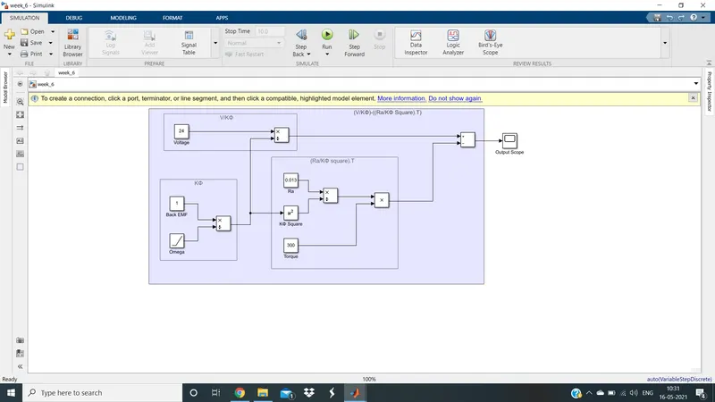
In the above model, we have considered the values as below
Voltage = 24V
Back EMF = 1
Armature Resistance = 0.013 Ohms
Torque = 300 Nm
The output of the above Simulink model of a DC motor using the above values is as shown below
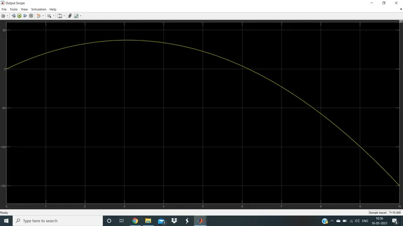
- The above figure is similar to that of the typical characteristics of a DC motor.
- We can alter the voltage, armature resistance, back EMF, and torque values of our motor as desired in the Simulink model and still obtain the output characteristics for the altered model.
Aim 4:
Refer to the blog on the below topic:
Induction Motors Versus Brushless DC Motors by Wally Rippel, Tesla
Explain in brief about author’s perspective.
Author's Perspective:
The author starts by highlighting the fact that “One Size Does Not Fit All”. In the world of gas vehicles, all engines are not all alike. One would have thought that, years ago, someone would have figured out which was best. That would have ended all the choices and thereafter only the one best engine type would be in production. But, there is no one best engine type, rather there are different types of engines to suit personal requirements, such as price and performance. This is also true for electric vehicle drives.
Having studied the various types of electric vehicle drives, the author identified that brushless DC drives and induction drives were the best available machines for HEV/EV. He also suggested that we will see both induction and brushless machines for many years to come. Each will have its loyal proponents and religious detractors for the reasons stated below.
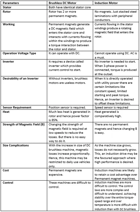
The author concluded by telling that DC brushless drives will likely continue to dominate in the hybrid and coming plug-in hybrid markets, and that induction drives will likely maintain dominance for the high-performance pure electrics. He also states the fact that so much of the hardware is common for both drives could mean that we will see induction and DC brushless live and work side by side during the coming golden era of hybrid and electric vehicles.