Week-6 Challenge: EV Drivetrain
1. Which types of power converter circuits are employed in electric and hybrid electric vehicle?
Power electronic converters are used in almost every aspect of everyday life, whether at home, in the workplace, or in an industrial setting.
These converters have become an integral part of industrial electrical drives, high electric power supplies, electric traction systems, and vehicle control equipment due to their high power handling capability and higher efficiencies.
Power converters are electrical and electronic circuits that are used to link direct current (DC) to alternating current (AC) or to convert one degree of direct current voltage to another (steps up or step down). There are various types of power electronic converters used to perform various functions (for example, inversion, rectification, etc.) that range in power from a few milliwatts to a few thousand watts.
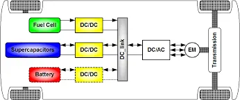
Power converters come in four varieties, but only three are used in EVs. There are three types of converters: AC to DC, DC to AC, and DC to DC.
AC TO DC CONVERTER (Rectifier)
A rectifier is an electrical device that transforms alternating current (AC), which reverses direction on a regular basis, to direct current (DC), which flows in just one direction.
Rectifier circuits can be either single-phase or three-phase. Most low-power rectifiers for household equipment are single-phase, but three-phase rectification is critical for industrial applications and energy transmission as DC (HVDC)
Single-phase rectifiers
Half-wave rectification
Half-wave rectification of a single-phase supply allows either the positive or negative half of the AC wave to pass while blocking the other half. It is a phase function (for positive pass, negative block): passing positive corresponds to the ramp function being the identity on positive inputs, blocking negative corresponds to the ramp function being zero on negative inputs.The mean voltage is lower since only half of the input waveform reaches the output. In a single-phase supply, half-wave rectification requires a single diode; in a three-phase supply, three diodes are needed. Rectifiers emit a pulsating but unidirectional direct current; half-wave rectifiers produce much more ripple than full-wave rectifiers.Moreover, much more filtering is needed to remove harmonics of the AC frequency from the output.
Full-wave rectification
At its output, a full-wave rectifier transforms the entire input waveform to one of constant polarity (positive or negative). This refers to the absolute value function in mathematics. Full-wave rectification transforms all polarities of the input waveform to pulsing DC (direct current), resulting in a higher average output voltage.It is enough to use two diodes and a center-tapped transformer, or four diodes in a bridge configuration and any AC source (including a transformer without a centre tap). As single elements, single semiconductor diodes, double diodes with a common cathode or common anode, and four- or six-diode bridges are manufactured.
If the transformer is center-tapped for single-phase AC, two diodes back-to-back (cathode-to-cathode or anode-to-anode, depending on output polarity required) will form a full-wave rectifier. The transformer secondary needs twice as many turns to produce the same output voltage as a bridge rectifier, but the power rating remains unchanged.
Three-phase rectifiers
Single-phase rectifiers are widely used in power supplies for household appliances. However, three-phase rectifier circuits are the standard for most industrial and high-power applications. Three-phase rectifiers, like single-phase rectifiers, may be half-wave circuits, full-wave circuits with a center-tapped transformer, or full-wave bridge circuits.Thyristors are often used in place of diodes to create circuits that can control output voltage. Many devices that provide direct current actually produce three-phase alternating current (AC). An automotive alternator, for example, contains six diodes that function as a full-wave rectifier to charge the battery.
DC to AC converter (Inverter)
DC to AC converters are mostly used to convert a DC power supply to an AC power supply. In this case, DC power supply is a relatively stable and positive voltage source, while AC oscillates around a 0V base point, usually in a sinusoidal or square mode.
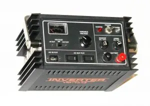
Inverter technology is commonly used in electronics to transform a voltage source from a battery into an alternating current signal. They usually work at 12 volts and are used in applications such as automobile, lead-acid technology, photovoltaic cells, and so on.A transformer system & a switch is the simple circuit used for an inverter. A typical transformer can be connected toward the DC signal’s input through a switch to oscillate back quickly. Due to the current flow in bi-directional in the primary coil of the transformer, an alternating current signal is an output throughout the secondary coils.
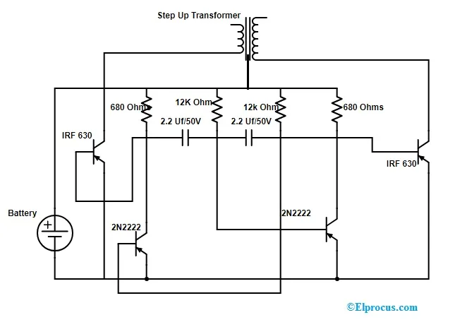
The DC to AC Converter Circuit with Transistors is illustrated below. An inverter circuit's basic purpose is to produce oscillations with the required DC and add them to the transformer's primary winding by increasing the current. Depending on the number of twists in the main and minor coils, the main voltage is then increased to a high voltage.
The circuit diagram of a 12V DC-to-220V AC converter can be made with simple transistors, and this circuit can be used to power lamps up to 35Watts, but it can be designed to drive more powerful loads by using more MOSFETs.
This circuit's inverter can be a square wave, and it works with devices that do not require pure AC sine wave.
The components needed to construct a DC to AC circuit primarily include a 12v battery, two 2N2222 transistors, two MOSFET IRF 630, two 2.2uf capacitors, two 12k resistors, two 680 ohm resistors, and a centre tapped transformer (step up)
DC to DC convertor
A DC to DC converter takes a voltage from a DC source and converts it to another DC voltage stage. They are used to raise or lower the voltage level. Automobiles, portable chargers, and portable DVD players are all examples of this. Some devices need a specific voltage to function.
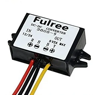
Too much power will kill the system, and too little power might not be able to operate it. A converter takes power from the battery and reduces the voltage level; similarly, a converter increases the voltage level. For example, it might be necessary to reduce the power of a large 24V battery to 12V in order to operate a radio.
A converter takes power from the battery and reduces the voltage level; similarly, a converter increases the voltage level. For example, it might be necessary to reduce the power of a large 24V battery to 12V in order to operate a radio.
There are various types of converters available.
Magnetic Conversion
In these DC-DC converters, energy is stored and released from a magnetic field in an inductor or a transformer on a regular basis at frequencies ranging from 300KHz to 10MHz. The amount of power transmitted to a load can be more easily regulated by changing the service cycle of the charging voltage.This control can also be used to adjust the input current, the output current, or to keep the power steady. The transformer-based converter can provide input and output isolation.
In general, the term DC-DC converter applies to the switching converters listed below. These are the circuits that control the switched-mode power supply. The circuits listed below are the most widely used.
Electronic Conversion
Switching technology is used in DC to DC converters in electronic circuits. A switched mode DC-DC converter transforms the DC voltage level by momentarily storing the input energy and then releasing it at a different voltage output. Magnetic field components such as inductors and transformers are used for storage, while electric field components such as capacitors are used for storage.The voltage level can be increased or decreased using this conversion process.
Switching conversion uses less power than linear voltage control, which wastes power as heat. A switched-mode converter's high efficiency decreases the amount of heat sinking needed and improves the battery endurance of portable equipment. Because of the use of power FETs, efficiency has improved.which are able to switch more efficiently with lower switching losses at higher frequencies than power bipolar transistors and use less complex drive circuitry. Another improvement in DC-DC converters is done by replacing the flywheel diode with synchronous rectification using a power FET, whose ‘on resistance’ is much lower, which reduces switching losses.Most DC-DC converters are designed to operate in a single direction, from input to output. However, by replacing all diodes with independently operated active rectification, switching regulator topologies can be configured to shift bidirectionally. For example, in vehicle regenerative braking, power is supplied to the wheels when driving,Hence a bi-directional conversion is useful.
Non-Isolated Converters
When the voltage change is minimal, non-isolated converters are used. In this circuit, the input and output terminals share a common ground. The various forms of converters in this category are as follows.
The downside is that it cannot guard against high electrical voltages and generates more noise.
Step-Down (Buck) Converter
A step-down circuit is used to produce a voltage that is lower than the input voltage. It is also known as a buck. The polarities are identical to those in the input.
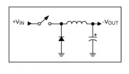
Step-Up (Boost) Converter
A step-up circuit is used to produce a voltage greater than the input voltage. It's known as a boost. The polarities are the same as they were in the input.
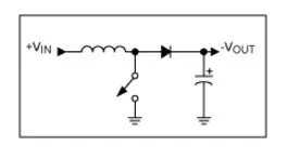
Buck-Boost Converter
The output voltage of a Buck-Boost Converter may be increased or decreased in relation to the input voltage. It operates by boosting or bucking the voltage. The most popular use for this converter is to reverse the polarity.
Cuk:The Buck-Boost converter is similar to this form of converter. The distinction is in its name, which is named after its creator, Slobodan Cuk.
Charge Pump: In low-power applications, this converter is used to step the voltage up or down.
Isolated Converters
The input and output terminals of these converters are separated. They have a high voltage isolation property. They have the ability to block noise and interference. This enables them to create a cleaner DC source. They are divided into two groups.
Flyback converter
This converter functions similarly to the non-isolating buck-boost converter. The difference is that instead of an inductor, it stores energy in the form of a transformer.
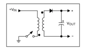
Forward Converter
The transformer will be used by this converter to send energy between the input and output in a single step.
2. An Electric Vehicle's powertrain with 72V battery pack in shown in the diagram below. The duty ratio for acceleration operation is 'd1' and for the braking operation the duty ratio is 'd2'.
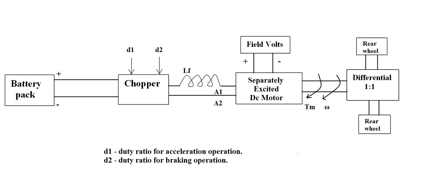
The other parameters of the electric vehicle is given below,
Motor and Controller Parameters:
Rated Armature voltage= 72 V
Rated armature current= 400 A
Ra= 0.5Ω, KΦ= 0.7 Volt second
Chopper Switching frequency= 400 Hz
The vehicle speed-torque characteristics are given by the below equation

What is EV steady state speed if duty cycle is 70%?
The speed torque equation of motor
`omega=V/K-((Ra)/K^2)*Tm`
Where,
Tm= Torque
V = Voltage
N (ω) = Motor Speed
Ra = Armature Resistance
K = Motor Constant (Armature control motor)
From this equation we can find the torque
`Tm=V/(Ra)*K-K^2/(Ra)*omega`
We can substitue the values given
`Tm=(50.4-0.7)/0.5-(0.7^2)/0.5*omega`
`Tm=70.56-0.98omega^2`
so
The given speed torque equation is
At steady state Tv=Tm
`24.7+0.0051*omega^2=70.56-0.98*omega^2`
so,
`0.0051omega^2+0.98w-45.85=0` we will get a quadratic equation
`ax^2+bx+c=0` in here a=0.0051 b=0.98 c=45.8`
For solving the QUADRATIC EQUATION , we have to use below formula,
`x=(-b+- sqrt(b^2-4ac))/(2a)`
so we have to put the a b c value in it
`x=(-0.98+-sqrt-0.98^2-4(0.0051)(45.85))/(2*0.0051)`
`x=omega`
`omega=38.92 (rad)/sec`
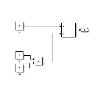
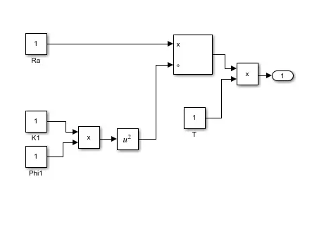
3. Develop a mathematical model of a DC Motor for the below equation using Simulink.
ω= V/Kϕ -Ra/Kϕ^2 .T
MAIN SYSTEM

In here there are two subsystem are there
v/Kϕ
Ra/(Kϕ)^2
4. Refer to the blog on below topic:
Induction Versus DC brushless motors by Wally Rippel, Tesla
Explain in brief about author’s perspective.
The author of the induction and DC brushless motor blog discussed the advantages and disadvantages of both induction and DC motors. The basic construction of both the induction and DC brushless motors is discussed in the blog.
Permanent magnets are used in DC brushless motors to generate a spinning magnetic field. When a magnetic field causes a current in a conductor. This current causes force generation in the rotor, which causes the rotor to rotate.In the case of an induction motor, current is supplied to the stator, resulting in the production of emf; when this emf comes into contact with the rotor, which is typically a squirrel cage type, current is induced in the rotor. Unlike a DC motor, the rotor is made up of conductor plates that are arranged in a cage-like structure.
One of the most noticeable differences is that the DC brushless drive generates significantly less rotor heat. This drive's rotor cooling is simplified, and its peak point performance is usually higher. It is stated that the DC brushless drive can drive at unit power factor, while the best power factor for the induction drive is about 85%.
The magnetic field strength is adjustable in the case of a DC brushless motor. When maximum torque is needed at low speeds, the magnetic field should be maximised, i.e. the inverter and motor current should be kept at their lowest to maximise performance.
In the case of an induction motor, however, no such modification is available.Magnetic losses increase proportionally as machine size increases, and component load performance decreases. In the case of an induction motor, losses do not usually increase with machine size.
Magnetic losses increase proportionally as machine size increases, and component load performance decreases. In the case of an induction motor, losses do not usually increase with machine size.
Owing to the use of permanent magnets, the installation of a DC brushless motor is more expensive than that of an induction motor. Despite the fact that the speed variation of an induction motor is dependent on the frequency input, it is difficult to regulate.
Conclusion
- As a result, all of the questions are completed in according with the conditions specified and all the required files are attached