Week-6 Challenge: EV Drivetrain
Qn. 1)Which types of power converter circuits are employed in electric and hybrid electric vehicle?
The power converter circuits that are used in electric and hybrid electric vehicles are:
1.Rectifier:
Rectifier is a power electronic circuit that converts electric power from AC to DC. They are majorly used in battery charging applications of the electric vehicles. It is because, the charging stations supply only AC power and this power has to be converted to DC inorder to charge the battery. In the present day, various topologies such as Interleaved topoligies have come for effective battery charging.
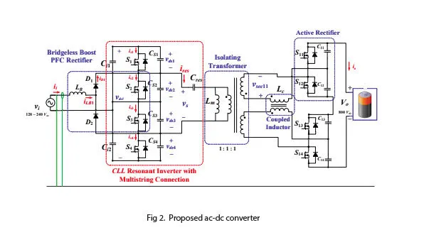
The above figure shows a practical AC to DC converter which are used in EVs.
2.Inverter:
Inverter is a power electronic circuit that converts electric power from DC to AC. They are generally used in the Motor Drives of the electric or hybrid electric vehicle. An electric vehicle consists of three phase induction motor which runs on AC. Hence, in order to run the motor from the battery power, it is necessary to convert the DC power from the battery to AC power. It generally uses power semiconductor switches such as MOSFET or IGBT. The output obtained is of alternating square wave in nature. But, various modulation techniques and control stratergies are used in order to obtain a sinusoidal output.
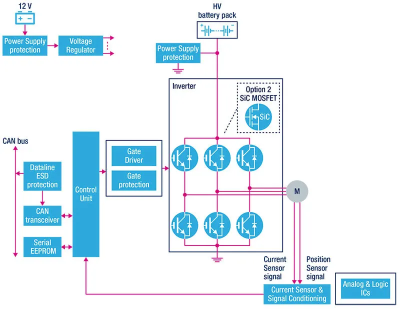
A traction inverter model for a EV/HEV is shown above.
3. DC-DC converter
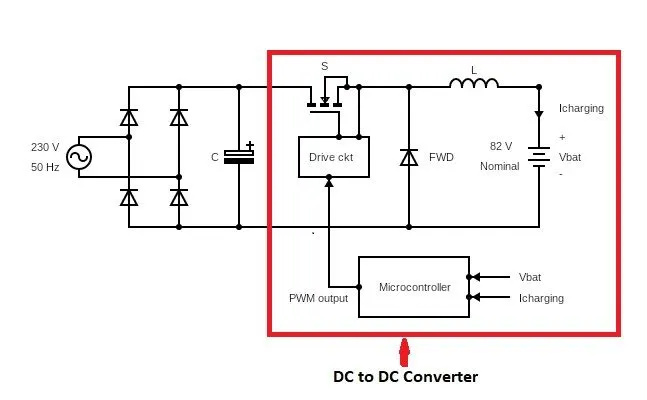
The main dc-dc converter changes dc power from an on-board 200-800V high voltage battery into lower dc voltages (48V or 12V) to power headlights, interior lights, wiper and window motors, fans, pumps and many other systems within electric vehicles (EV) and hybrid electric vehicles (HEV). This high voltage to low voltage (HV-LV) dc-dc converter is often referred to as an auxiliary dc-dc, or Auxiliary Power Module (APM). Isolation is critical for separating the control systems from high-voltage domains. A DC-DC converter supplies conventional low-power, low-voltage loads. However, the need for high power bidirectional DC- DC converters in future electric vehicles has led to the development of many new topologies of DC-DC converters. Several DC-DC converters such as isolated, nonisolated, half-bridge, full-bridge, unidirectional and bidirectional topologies are used in electric vehicles.
Q2.)
Given:
Battery Pack voltage= 72V
Duty cycle= 70%=0.7
Rated Armature voltage= 72 V
Rated armature current= 400 A
Ra= 0.5Ω
KΦ=K= 0.7 Volt second
Chopper Switching frequency= 400 Hz
The vehicle speed-torque characteristics are given by the below equation:
`T=24.7+(0.0051) omega^2`.............eqn.1
we already know that,
`=> T= (KV)/R_a- (K^2/R_a)*omega`.......eqn.2
where V is the voltage given to the motor.
Here `V= delta*V_b` where `V_b`is the battery voltage
`=> V= 0.7 xx 72 =50.4`
`therefore T= (0.7 xx 50.4)/0.5- (0.7^2 xx omega)/0.5` (from eqn.2)
`=> T=70.56-0.98omega`. Substitute this in eqn.1,
`=> 70.56-0.98 omega= 24.7+0.0051 omega^2`
`=> 0.0051 omega^2+0.98omega-45.86=0`
Solving for `omega` , we get,
`omega= -231.07 or omega=38.91`
Speed= -231.07 rad/s is not valid.
Therefore, the steady state speed is 38.91 rad/s
Qn.3)Develop a mathematical model of a DC Motor for the below equation using Simulink.
Equation: `omega = (V/K)-(R_a/K^2)*T`
The simulink model is given below:
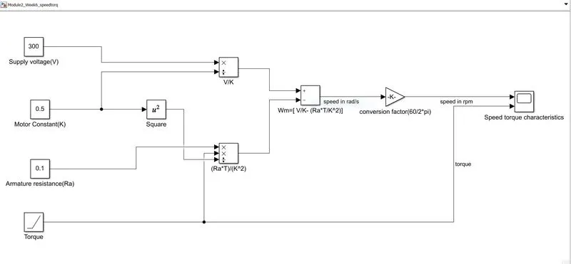
The above equation is built using basic simulink blocks. The speed is found and then converted to RPM by multiplying with the corresponding conversion factor. Torque is given as ramp input as we need to observe the speed variation as the torque increases. The simulation is run for 1500s and the results are observed as follows.
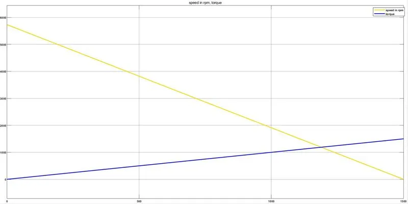
Therefore as the torque increases, the speed decreases which is correct as per the given equation.
Qn.4)Refer to the blog on below topic: Induction Versus DC brushless motors by Wally Rippel, Tesla
Explain in brief about author’s perspective.
In the blog, the author simply compares the motors that could be used in an EV or an HEV.
| BRUSHLESS DC MOTOR | THREE PHASE INDUCTION MOTOR |
| The rotor includes two or more permanent magnets that generate a DC magnetic field. | Unlike the DC brushless rotor, the induction rotor has no magnets – just stacked steel laminations with buried peripheral conductors that form a “shorted structure.” |
| The magnetic field enters the stator core (a core made up of thin, stacked laminations) and interacts with currents flowing within the windings to produce a torque interaction between the rotor and stator. | The rotating magnetic field due to the currents flowing in the stator windings interacts with the rotor and by faraday's law, an emf is induced in the rotor. Since rotor is a closed circuit, current flows and it experiences a torque. |
| Current control device namely inverter is a MUST to maintain torque constant. | No inverter is needed. |
| A brushless DC motor produces no starting torque when directly connected to fixed frequency utility power. They really need the aid of an inverter whose “phase” is maintained in step with the angular position of the rotor. | The fact that induction motors are directly compatible with conventional utility power is the main reason for their success. |
| Technically better motor but it fails in economical and practical aspects. | They have great utility but several limitations.These limitations can be overcome by employing various techniques. |
| Less rotor heat is generated with the DC brushless drive due to which rotor cooling is easier and peak point efficiency is generally higher for this drive. | More heat is generated and cooling techniques are difficult. |
| Operates at unity power factor | The best power factor for the induction drive is about 85 percent. |
| Efficiency is high compared to Induction motors | Efficiency is slightly low compared to DC brushless. |
| Hysterisis and Eddy current losses are high due to fixed magnetic field density(B) | Hysterisis and Eddy current losses are low as the magnetic field density can be varied by V/f control |
| With DC brushless, as machine size grows, the magnetic losses increase proportionately and part load efficiency drops. | With induction, as machine size grows, losses do not necessarily grow. Thus, induction drives may be the favored approach where high-performance is desired |
| Peak efficiency is more | Average efficiency is more |
| Costlier | Comparitively less costly. |
Conclusion by the author:
The author concludes that DC brushless drives will likely continue to dominate in the hybrid and coming plug-in hybrid markets, and that induction drives will likely maintain dominance for the high-performance pure electrics.