Week -2
Qn. 1) Simulink Model of Doorbell
Aim: To make a simulink model of doorbell using 'solenoid' block.
Theory of Solenoid:
A solenoid is just an electromagnet where the coiled wire surrounds a metal piston. The piston contains magnetically conductive metal, so it can be moved backward or forward by the electromagnetic field. It works on basic magnetic principle which states that a current carrying conductor placed in a magnetic experiences a force.The following video shows the animation of the solenoid:
Initial Approach:
- Reading the Matlab documentation of solenoid about its port,parameters and working.
- Trying to build the electrical side and mechanical side with solenoid acting as the mediator.
- The electrical side consisted of a "Controllable Voltage Source" controlled by a "Signal Builder".[Note: The Signal builder was made with the step kind of signal with Total period=4s and On period=2s]
- The mechanical side consisted of "Ideal Translational Motion Sensor"
- The respective signals are converted using the "PS-Simulink Converter" and "Simulink-PS Converter" and then viewed through a scope.
Limitation Of the Initial approach: The initial approach was built with the idea that the combination of Controllable Voltage Source with Signal Builder can act like a time specified excitation of the solenoid. But since Signal Builder has a specific time range, The visualisation of the periodicity of the plunger position was not possible. Hence I went for the Battery and Switch model where the switch was controlled using a pulse generator.
Troubleshooted Approach:
- The electrical side consisted of simulink blocks of "Battery" and a "Switch" which is controlled by a 'Pulse Generator"
- The mechanical side consisted of "Ideal Translational Motion Sensor"
- The respective signals are converted using the "PS-Simulink Converter" and "Simulink-PS Converter" and then viewed through a scope.
Reason to use two Scopes: The Amplitude of the "Pulse generator" is 1 unit whereas the displacement of the plunger in solenoid is in milliunits. When both the signals are given to same scope, then the visualisation becomes difficult. Hence, both are visualised in two different scopes.
SIMULINK MODEL OF THE DOORBELL:
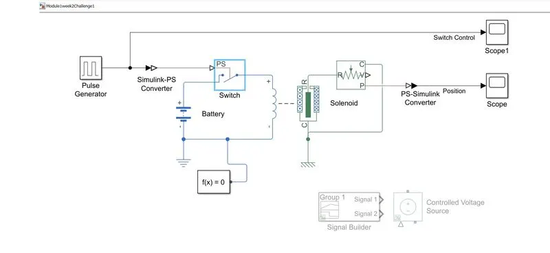
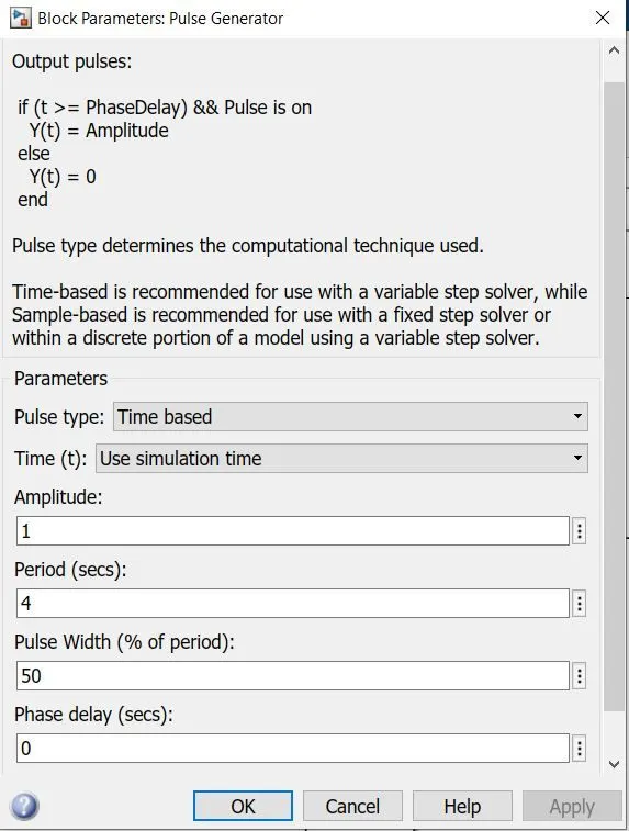
Note: All the blocks are assumed with default parameters except Pulse Generator
Parameters of Pulse generator:
Scope View of the Pulse Generator:
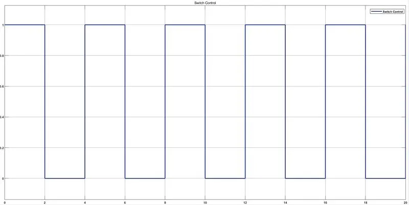
We can see that the pulse is given for 2 seconds in a total time period of 4 seconds.
Working of the Model:
The switch has a default threshold value of 0.5 and Pulse Generator has a amplitude of 1. So from t=0s to t=2s when the amplitude of the pulse is greater than the threshold value of the switch, the switch is closed. When the switch is shorted, the solenoid is energised as the battery is connected. As the solenoid is energised, The plunger moves which is sensed by the "Translational Motion sensor". This repeates for cycle of the pulse generator.
Scope view of the Plunger Movement:
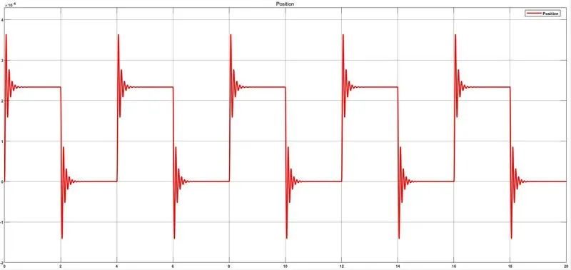
Hence the above picture shows the physical movement or the displacement of the Plunger when the solenoid is energised.
Conclusion: Thus the simulink model of a door bell is created and the physical movement of the plunger is analysed.
Qn. 2) Thermistor Controlled Fan using simulink
Aim: To simulate the operation a fan based on given conditions using a thermistor with the aid of Simulink.
Conditions Given:
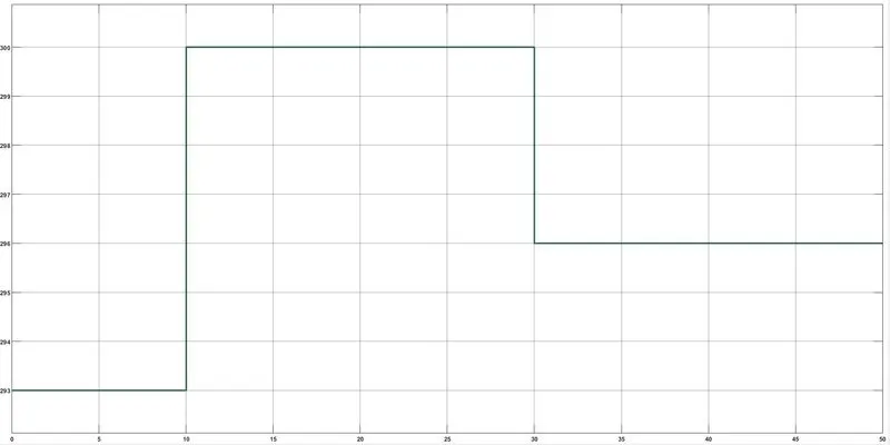
Temperature source: 20 °C (273K) from 0 to 10 seconds, 27 °C (300K) from 10 to 30 seconds, 23 °C (296K) from 30 to 50 seconds
Fan conditions: ON if the temperature above 25 °C(298K), OFF otherwise
Approach:
- To get the required temperature variation with respect to time using "Controlled Temperature Source" controlled by a "Signal Builder"
- To find the threshold value of current in the thermistor in the temperature range for which the fan is desired to operate.(i.e. It is given that fan should be ON when the temperature is above 298K. Hence we need to find the current corresponding to the temperature of 298K)
- The threshold value is found in order to feed that value into switch so that the switch operates whenever the given value exceeds the threshold value
- The final signal from the switch can be then used as control signal or direct signal to run the fan.
Note: For the sake of simplicity, The actual fan block is not simulated as the actual fan requires complex systems such as Induction motor. Simulation is done till we get the final resultant signal which will be present whenever the temperature is above 298K according to the given condition.
One of the key elements in detecting the temperature and using it for controlling electrical signals is the Thermistor.
Thermistors: Thermistors are thermally sensitive resistors whose prime function is to exhibit a large, predictable and precise change in electrical resistance when subjected to a corresponding change in body temperature. Negative Temperature Coefficient (NTC) thermistors exhibit a decrease in electrical resistance when subjected to an increase in body temperature and Positive Temperature Coefficient (PTC) thermistors exhibit an increase in electrical resistance when subjected to an increase in body temperature.
The thermistor block used in the simulink is a NTC.
Simulink Block model to find the threshold value:
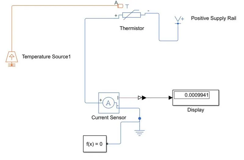
In the above model, a constant temperature source along with a thermistor is used. The Temperature Source is fed with the temperature of 298K for which we need to know the current value. The current value is given by the current sensor which is displayed in the display as "0.0009941"
Overall Simulink Block model:
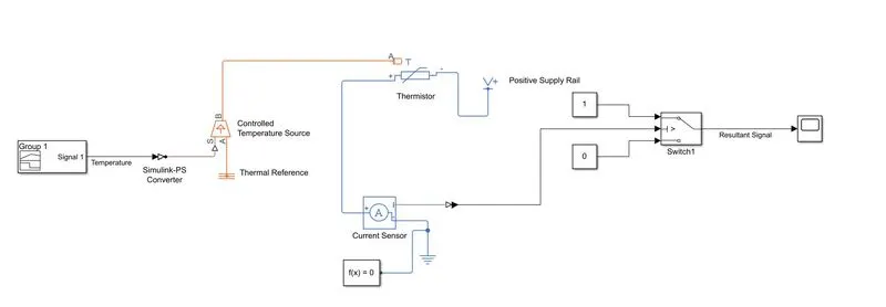
Working: The Controlled Temperature source is connected to the thermistor as shown. The control signal for temperature source is built using Signal Builder according to the condition given. It is as given below
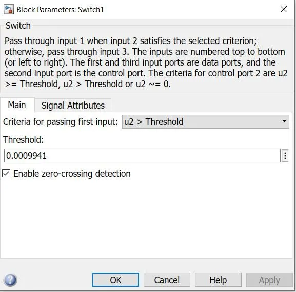
The thermistor senses the heat and a current flows in the closed circuit when a "Power Supply Rail" of 1V is connected with the thermistor. The current sensor senses that current and feeds it into the "Switch". The Switch is fed with the threshold value of 0.0009941 which we found before. The Switch basically passes input 1 when the fed value is greater than the threshold or it passes input 2 when the fed value is lesser than threshold. We have given input 1 as constant "1" and input 2 as constant "0" just to acknowledge the resultant signal through the scope.
Switch Parameters:
The Resultant Control Signal to drive the Fan:
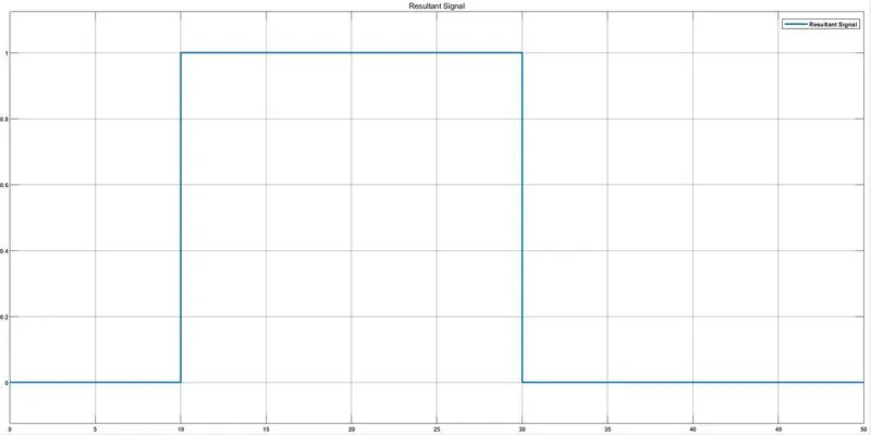
Thus we could see that we get a signal from t=10s to t=30s where the temperature is above 25 °C or 298K. This signal could be used as a pulse to then drive a fan.