Week - 4
Qn. 1)Implementation of control logic of a washing machine using state flow
Objective
To implement control logic of a “washing machine” using Stateflow as per given sequence:
- If the power supply is available, the system gets activated
- If the Water supply is not available, stop the process & indicate through LED
- Soaking time should be 200s followed by Washing time of 100s.
- Then rinsing happens for next 20s & dryer runs for 50s.
Developed Simulink Model:
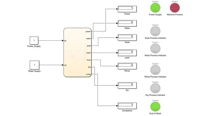
Description of the Model:
- The constant block "Power_Supply" indicates the electrical power given to the washing machine. (i.e 1 indicates that the power supply is given and "0" indicates that the power supply is not given)
- The constant block "Water Supply" indicates the water given to the washing machine. (i.e 1 indicates that the water is given and "0" indicates that the water is not given)
- These two inputs are given to the flow chart and according to the logic given in the chart, we get different outputs.
- Each output port is given to a display. The number "1" in the display indicates the particular process ongoing.
- A lamp is also given for a better user interface.
Colour Code of lamp:
Green indicates positive affirmation. For example:
- Green color in "Power Supply" lamp indicates that the power supply is present.
- Green color in "Machine Process" lamp indicates that the washing process is still going on and not completed yet.
- Green color in "End of Wash" lamp indicates that the Washing Process is completed fully.
Red Indicates negative situation. For Example:
- Red color in "Power Supply" lamp indicates that the power supply is NOT present.
Orange is specifically given for indicating various processes such as soaking,washing,rinsing etc.
Stateflow
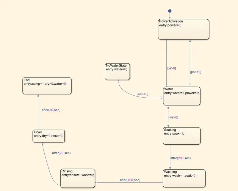
Explanation: The Initial state is assigned with "power=0". The input power supply is then checked and if it is greater than "0"(means Power supply is present), the flow jumps to the next state where a variable "water" is assigned with "1". Also, the "power" variable is assigned with "1"[To indicate in lamp]. The control logic then checks for the water supply. If water supply is present, the "Soaking" state is activated. If water supply is NOT present, then the variable "water" is assigned with zero and the process terminates abruptly. In the "Soaking" state, the variable "soak" is assigned with 1 to indicate in display that the current soaking process is going on. The control then jumps to "Washing" state automatically after 200s where the variable "wash" is assigned with 1 to indicate in display that the washing process is going on and the variable soak is assigned with 0 as the soak process is over . Once washing is over, the control jumps to "Rinsing" state after 100s. After 20s, the control then jumps to "Dryer" state which is ended after 50s and the washing process is completed. Once the control reaches the "End" state, the variable "comp" is initialised with 1 to indicate completion is display. And also the "water" variable is assigned with "0" to make the "Machine Process" lamp glow red.[As the washing process is completed]
Simulation Results when run for 400s when both Power Supply and Water Supply is given:
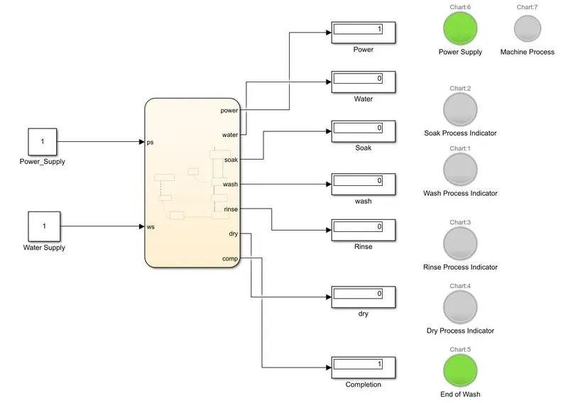
Hence, we could see that after 400s, the washing process is completed which indicated by the "Completion" display displaying "1" and also by "End of Wash" lamp glowing green.
Simulation results when Power supply is NOT given:
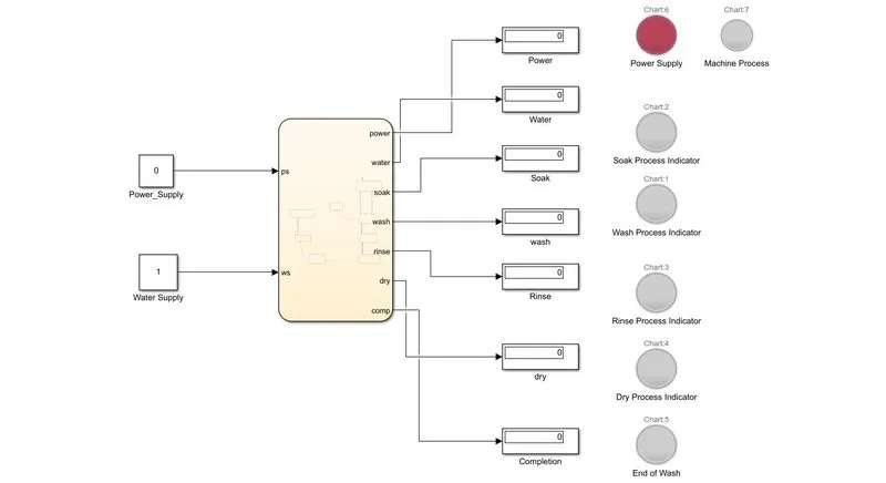
Hence we can see that when power supply is NOT given, no process is initiated and also the power supply lamp glows red meaning that there is no electric power supply.
Simulation results when Water supply is NOT given:
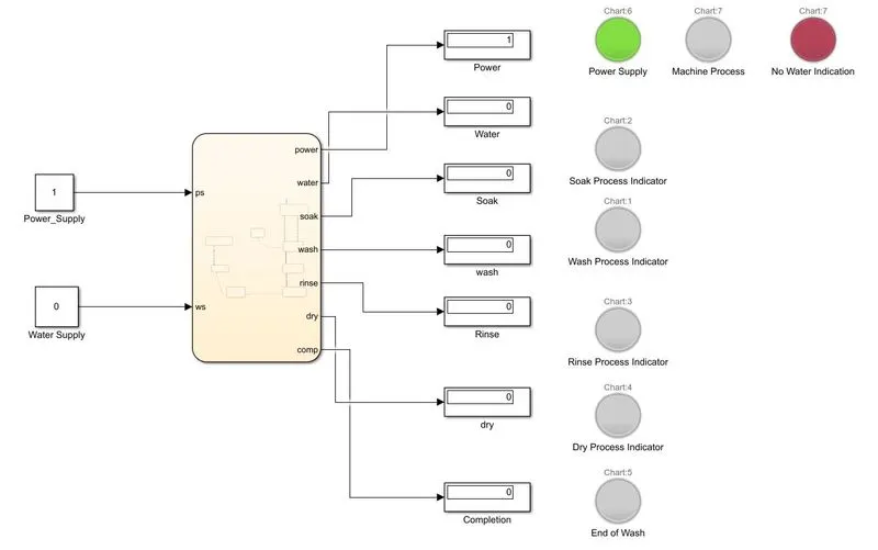
The constant block indicating "Water Supply" is given "0", which is analogous to NO water supply. Under such conditions, when the simulation is run, we can see that all display indicates zero which means no process has occured. Also, the "No Water Indication" is glowing red showing that is there is no water supply and process has terminated.
Simulation of model after 100s when both Power Supply and Water Supply is given:
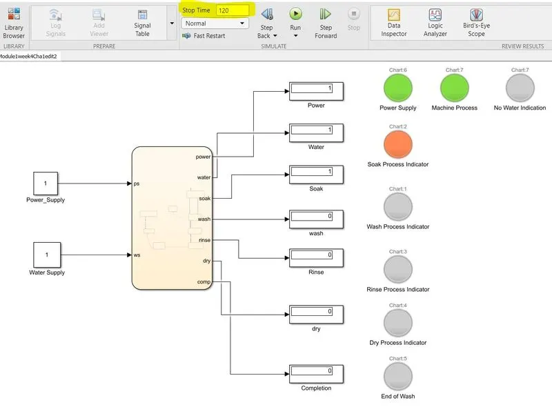
Hence, we could see that after 100s, the machine is in soak state which is indicated by the "1" in the display as well as by the lamp glowing orange.
Simulation of model after 200s when both Power Supply and Water Supply is given:
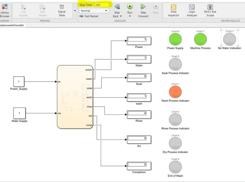
Hence, we could see that after 200s, the machine is in wash state which is indicated by the "1" in the display as well as by the lamp glowing orange.
Similarly, The other processes can be verfied by running the simulation for various time instants.
Qn. 2)Implementation of Gear shift logic using simulink chart :
Objective:
To make a Simulink chart for the “Gear shift” logic as per below conditions:
Speed Range(kmph) Gear
0 to 15 1
16 to 25 2
26 to 40 3
41 to 60 4
Above 61 5
Give speed input while the simulation is running & display the gear number.
Simulink Model:
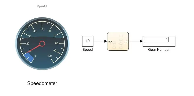
Description of the Model:
- The speed input is given using a constant block. A speedometer display is also given for a better user interface.
- The given speed input is processed in the charts according to the given algorithm and the gear number is displayed in the display
The Chart
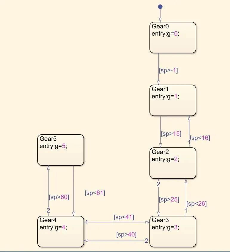
Explanation: Initially once input is given, the "Gear0" state is activated and it checks for the condition if the speed is greater than or equal to 0. If that condition is true, the control jumps to "Gear1" state where the variable "g" is initialised with value "1". Conditional Statements are given according to the given logic so that the states shift accordingly.
Let us analyse the outputs for various values of speeds:
When speed=15Km/hr,
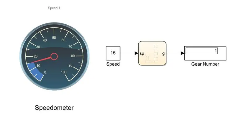
Hence when the speed is 15Km/hr, the Gear Number is displayed as "1" which is true according to the given logic.
When Speed=20Km/hr
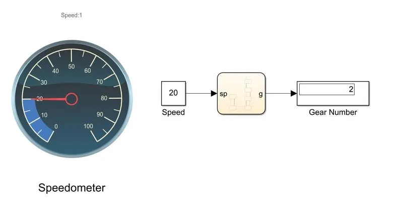
Hence when the speed is 20Km/hr, the Gear Number is displayed as "2" which is true according to the given logic.
When Speed=40Km/hr,
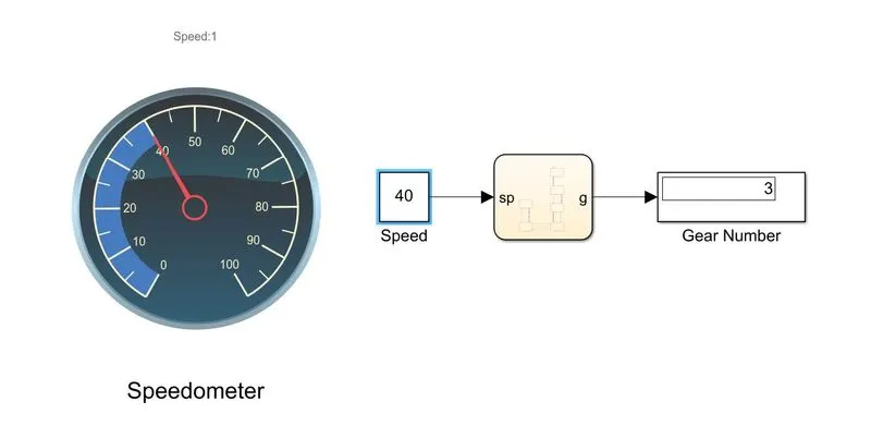
Hence when the speed is 40Km/hr, the Gear Number is displayed as "3" which is true according to the given logic.
When Speed=55Km/hr,
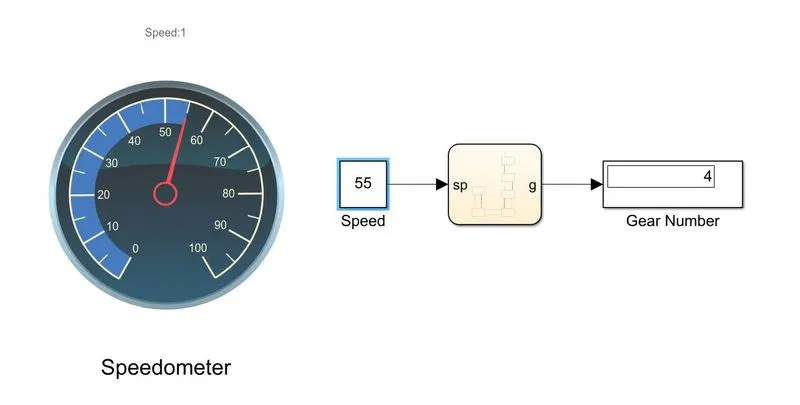
Hence when the speed is 55Km/hr, the Gear Number is displayed as "4" which is true according to the given logic.
When Speed=90Km/hr,
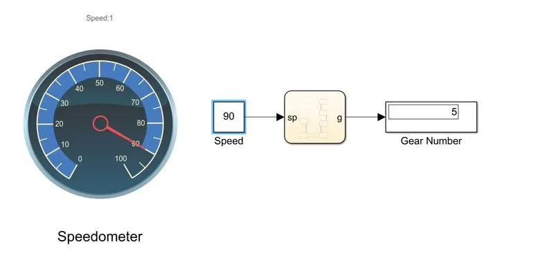
Hence when the speed is 90Km/hr, the Gear Number is displayed as "5" which is true according to the given logic.
Hence, the gear model is simulated for all ranges of speed and output results are verified.