Week-6 Challenge: EV Drivetrain
WEEK-6 :-EV DRIVETRAIN
Aim:
1:- To tell which types of power converter circuits are employed in electric and hybrid electric vehicles.
2:- To find out the steady state speed of an EV with given specifications and duty ratios as ‘d1’ during acceleration and ‘d2’ during deceleration.
3:- To explain briefly about the author’s perspective in a given blog:
Induction Versus DC brushless motors by Wally Ripple, Tesla
1: Different types of power converters that are employed in an electric and HEV:
Power converters or power electronic converters are used everywhere in normal daily life at home, commercial workplaces or in an industrial environment and even in EV’s and HEV’s. due to high handling of the power with high efficiencies, they became an integral part of industrial electric drives and components There are different types of power electronic converters used for performing different functions (such as inversion, rectification, etc.) which are rated from a few milliwatts to a few thousand watts. Let us look at these converters in detail.
A power electronic converter uses power electronic components such as SCRs, TRIACs, IGBTs, etc. to control and convert the electric power. The main aim of the converter is to produce conditioning power with respect to a certain application.
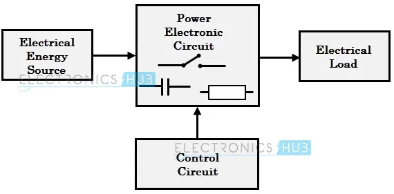
Fig(1): Block diagram of a general power electronic converter.
The power electronic circuit consists of both power part and control part. Power part transfers the energy from source to load and it consists of power electronic switches (SCR or TRIAC), transformers, electric choke, capacitors, fuses and sometimes resistors. The control circuit or block regulates the elements in the power part of the converter. This block is built with a complex low power electronic circuit that consists of either the analog or digital circuit assembly. They can be uni or bi-directional.
Depending on the type of function performed, power electronic converters are categorized into following types.
- AC to DC - (Rectifier)
- DC to AC - (Inverter)
- DC to DC - (Chopper)
- AC to AC - (Cycloconverter)
AC to DC = Rectifier:
It converts AC to unipolar (DC) current. The essential components of the rectifier are transformer, switching unit, filter and control block. The inverter can change the speed at which the motor rotates by the frequency of the AC and can also increase or decrease the power/torque of the motor by changing the amplitude of signal accordingly.
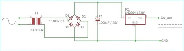
fig(2): circuit diagram of a AC-DC converter
DC to AC = Inverter: It converts DC to AC of desired frequency and voltage. Usually used when AC motor is used to drive the vehicle. The battery pack in the EV and HEV’s will supply the power to the inverter which contains a transformer which consists of a primary and secondary winding. The current is sent to primary winding where the direction of the current is reversed to create an AC waveform which include an AC in the secondary winding that supplies the current to the AC load.
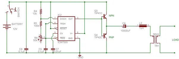
Fig(3): circuit diagram of DC-AC converter.
DC to DC = Chopper: It converts constant to variable DC or variable DC to constant DC.
The DC-DC converters can be used as follows in the EV and HEV’s. They can provide low voltages for low loads and can boost voltage levels of the battery such that it matches the level of the DC voltage for driving the AC inverter. These are used for traction motors in AC motor and in motor propulsion if the traction motor is a DC motor.
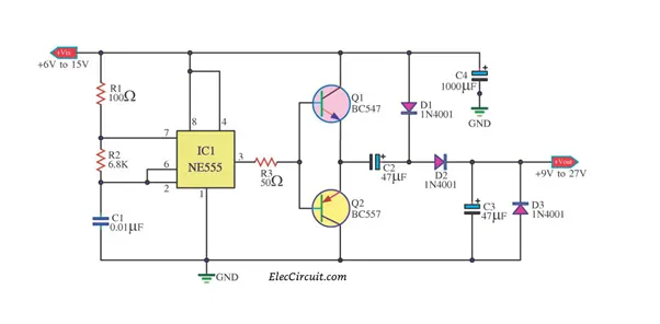
Fig(4): circuit diagram of DC-DC converter.
AC to AC = Cycloconverter, Matrix converter: It converts AC of desired frequency and/or desired voltage magnitude from a line AC supply. This converter can convert from fixed AC to variable AC output voltage and it is controlled by varying firing angle of TRIAC. These are also called as AC voltage regulators.
2: To find the steady state speed of the motor with given details:
Given that,
EV's powertrain with a 72V battery pack and the duty ratio for accelaration as 'd1' similarlly for decelaration the duty cycle is indicated as 'd2'
Rated armature current = 400A
Rated armature voltage = 72V
`R_a = 0.5 Omega`
`k phi = 0.7`volt second
chopper frequency = 400 Hz.
the vehicle speed-torque characteristics equation is
`Tv = 24.4 + (0.0051)w^2` ... equation (1)
for the steady state speed at 70% duty cycle is
`(V_m)= V_(bat)*0.7 =50.4` volts
from torque-speed characteristics equation
`T = V((Kphi)/R_a)- ((Kphi)^2/R_a)*omega` ...... equation (2)
by substituting the given values in the above equation, we get
`T = 50.4 * (0.7/0.5) - ((0.7)^2/0.5)*w`
`= 70.56 - 0.98*w` ... equation (3)
By comparing the equations (1) and (3) we get the equation as `70.56 - 0.98*w - 24 + (0.0051)*w^2 = 0`
--> `0.0051*w^2+0.98*w-45.86=0` ... equation (4)
as the equation (4) represents a quadratic equation by solving the roots of quadratic equation, we get:
`x = ((-b+- sqrt(b^2 - 4ac))/(2a))`
we get`x = -0.98+- 1.3770.0102`
w = 38.85 rad/sec and -230.98 rad/sec by conisdering the positive values,
the steady state speed of the vehicle is 38.85 rad/sec
3: To explain briefly about the author’s perspective in a given blog:
Induction Versus Dc brushless motors by Wally Ripple, Tesla
The author in the block throws a spotlight on the change in trend of technology. He gives in detailed explanation of the induction motors and DC brushless motors, their similarities and differences in construction, working and even the cost between them.
Major characteristics of the DC brushless motor and induction motor are:
- Both are identical but difference between two machines is with the rotor.
- DC had the magnets but the induction has a stack of steel laminations with the buried peripheral conductors.
- The 3-phase induction motor doesn’t need any kind of inverter as the motor has the ability to start under load where as the brushless DC produces no starting torque when directly connected to fixed frequency power.
- Unlike the DC motor, the 3-phase induction can’t operate from DC; AC is must.
- The heat generation in rotor of DC brushless is much less when compared to the other and rotor cooling is easier thus the peak point efficiency is higher for this drive.
- Adding an inverter in induction motor is possible from a battery or other source thus variable speeds can be maintained by adjusting the inverter frequency but still the torque is less compared to DC machines.
Ripple concludes that DC motors will dominate in EV and HEV markets and induction motors will be dominating in the performance in pure electrics. He says that both are better in their own ways.