Week-6 Challenge: EV Drivetrain
AIM:
- Which types of power converter circuits are employed in electric and hybrid electric vehicle
- An Electric Vehicle's powertrain with 72V battery pack in shown in the diagram below. The duty ratio for acceleration operation is 'd1' and for the braking operation the duty ratio is 'd2'.
- Refer to the blog on below topic:
Induction Versus DC brushless motors by Wally Rippel, Tesla
Explain in brief about author’s perspective.
- Which types of power converter circuits are employed in electric and hybrid electric vehicle?
Power converter is to process and control the flow of electrical energy by supplying voltages and currents in a form that is optimally suited for user loads.
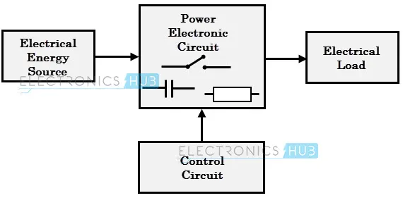
The different types of converters used in an electric and hybrid electric vehicles are:
- A.C – D.C Converter
- D.C – D.C Converter
- D.C – A.C Converter
- A.C – D.C Converter
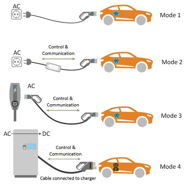
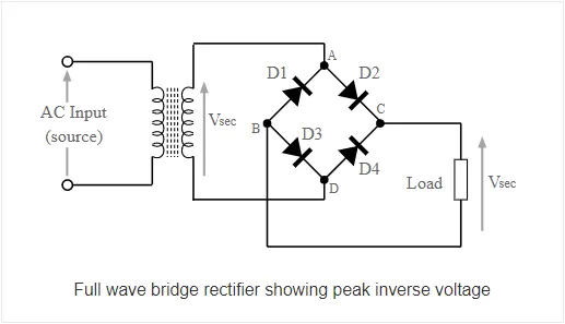
A.C – D.C Converter are electrical circuits that convert A.C (alternating current) input into D.C (direct current) output. These converters are used in charging circuits in which the charging point outlet is an A.C and batteries require D.C current charge to change. So these converters uses rectifiers to turn A.C input into D.C output.
The circuit diagram for a rectifier:
- D.C – D.C Converter
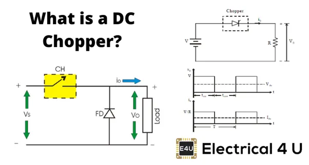
D.C- D.C Converter is also called as chopper which converts high voltage to low voltage and vice versa. In electric vehicles they are used convert high voltage to low voltage. For eg: if the battery voltage is of 100V then it converts it into 12V or 30V according to the requirement. This is used to run auxiliary components like headlights, sound system, and air- conditioning system. DC-D.C converter is also responsible for stepping up and stepping down the voltage.
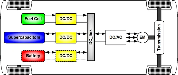
The circuit diagram for D.C – D.C Converter
- D.C – A.C Converter
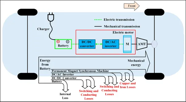
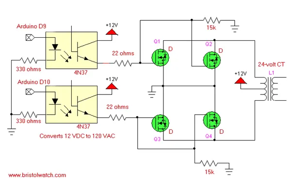
D.C – A.C converter are electrical circuits that convert D.C input into A.C output. An inverter is used that converts D.C power from the battery to A.C power used in an electric vehicle. The inverter can change the speed at which the motor rotates by adjusting the frequency of alternating current. It is used in electrical system for running components such as induction motor.
The circuit diagram for inverter:
- An Electric Vehicle's powertrain with 72V battery pack in shown in the diagram below. The duty ratio for acceleration operation is 'd1' and for the braking operation the duty ratio is 'd2'.
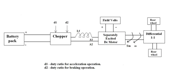
The other parameters of the electric vehicle is given below,
Motor and Controller Parameters:
Rated Armature voltage= 72 V
Rated armature current= 400 A
Ra= 0.5Ω, KΦ= 0.7 Volt second
Chopper Switching frequency= 400 Hz
The vehicle speed-torque characteristics are given by the below equation
What is EV steady state speed if duty cycle is 70%?
Average velocity = battery voltage x duty cycle
= 72 x 0.7
= 50.4 V
SPEED – TORQUE EQUATION OF A D.C MOTOR:
ω = v/kØ – Ra / (Kø) 2 X T
Ra = armature resistance ohms
ω = angular velocity in rad/sec
Kø = motor constant
V = rated battery voltage
T = torque
ω = 50.4 / 0.7 – 0.5 / (0.7)2 x T
ω = 50.4 / 0.7 – 0.5 / (0.49) x T
ω = 35.28 – 0.5 T / 0.49
0.49 ω = 35.28 – 0.5 T
0.49 ω = 35.28 – 0.5 T
0.49 ω + 0.5 T – 35.28 = 0
0.5T + 0.49 ω – 35.28 = 0
0.5T = 35.28 – 0.49 ω
T = 35.28 – 0.49 ω /0.5
Substituting the value of T in the given equation
35.28 – 0.49 ω / 0.5 = 24.7 + 0.0051 ω2
35.28 – 0.49 ω = (24.7 + 0.0051 ω2) 0.5
35.28 – 0.49 ω = 12.35 + 0.00255 ω2
35.28 – 0.49 ω – 12.35 – 0.00255 ω2 = 0
0.00255 ω2 + 0.49 ω - 35.28 + 12.35 = 0
0.00255 ω2 + 0.49 ω - 22.93 = 0
Equation to find the value of ω
X = -b ± √ b2 – 4ac /2a
ω = - 0.49 ± √ (0.49)2 - 4 x 0.00255 x – 22.93 / 2 x 0.00255
ω = - 0.49 ± √ 0.4739 /2 x 0.00255
ω = - 0.49 ± √0.4739 / 0.0051
ω = - 0.49 + 0.6884 /0.0051
ω = 0.1984 / 0.0051
ω = 38.901 rad /s
OR
ω = - 0.49 - 0.6884 /0.0051
ω = -1.1784 / 0.0051
ω = - 231.05 rad /s
- Refer to the blog on below topic:
Induction Versus DC brushless motors by Wally Rippel, Tesla
Explain in brief about author’s perspective.
|
BRUSHLESS D.C MOTOR |
INDUCTION MOTOR |
|
The rotor includes two or more permanent magnets and the stator comprises of many coils when D.C current is passed through the coils these coils get energised and becomes an electromagnet and it is based on the operation between the interaction of permanent magnet and electromagnet. |
Induction motor consists of a rotor and the stator. Stator is a three coil winding passing through the slots of the stator which is made up of thin high permeable steel lamination inside a steel or cast iron frame. When A.C current passes through the windings a rotating magnetic field is produced. This rotating magnetic field causes the rotor to turn. |
|
Brushless D.C has two or more permanent magnets. |
Induction motor has no magnets |
|
Less rotor heat is generated and this motor operates at unity power. |
Rotor cooling is easier and peak point efficiency is generally higher for induction motor. The power factor for induction motor is about 85 %. |
|
D.C machines have higher starting torque and high running peak torque capabilities |
The limitation is it can work in A.C only. The speed is proportional to frequency and has limited torque. Hence an inverter is added to a D.C source/battery, the frequency is adjusted on the inverter and also feedback loops are added to produce exact frequency as the motor desires.Hence variable speed is achieved for vehicle application. |
|
In brushless D.C motor as the machine size grows, there is in an increase in magnetic losses that causes the load efficiency to drop , which makes it not suitable for high performance |
As the motor size grows, magnetic losses does not necessarily increase which makes it more suitable where high performance is desired. |
|
Permanent magnets are expensive |
Cost will be less as compared to brushless D.C motor |
|
Brushless D.C motor will mostly dominate the hybrid and plug – in hybrid markets. |
Induction motor is likely to maintain dominance for high- performance pure electrics. |
CONCLUSIONS
1. The different types of converters used in an electric and hybrid electric vehicles are:
a. A.C – D.C Converter
b. D.C – D.C Converter
c. D.C – A.C Converterc
2. Since the vehicle is in the forward direction we are considering the positive of ω = 38.901 rad/s which is the vehicle steady speed, if the duty cycle is 70%.
3. The blog discusses the differences between brushless DC motors and Induction motors. Both are useful in its own ways.