Week-6 Challenge: EV Drivetrain
AIM -
1. To find types of power converter circuits are employed in electric and hybrid electric vehicle.
2. An Electric Vehicle's powertrain with 72V battery pack in shown in the diagram below. The duty ratio for acceleration operation is 'd1' and for the braking operation the duty ratio is 'd2'. The other parameters of the electric vehicle is given as, Motor and Controller Parameters: Rated Armature voltage= 72 Rated armature current= 400 A Ra= 0.5Ω, KΦ= 0.7 Volt second Chopper Switching frequency= 400 Hz. What is EV steady state speed if duty cycle is 70%?
3. Refer to the blog on below topic: Induction Versus DC brushless motors by Wally Rippel, Tesla. Explain in brief about author’s perspective.
1. Types of power converter circuits are employed in electric and hybrid electric vehicle.
A. DC - DC converters
1.Boost DC-DC Converter (BC) -
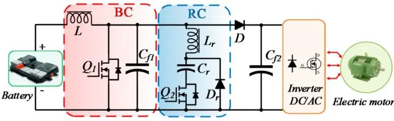
The boost DC-DC converter is a power converter that steps-up the input voltage while stepping down the input current. It is a class of switched-mode power supply (SMPS) having at least one energy storage element (a capacitor, an inductor, or the two in combination) and at least two semiconductors (a diode and a switch) In BC, a series connected inductor with the input DC source helps to reduce input current ripples and a capacitor-based filter is used at the output side to eliminate the output voltage ripples. Boost DC-DC converters have various advantages. A moderate output voltage gain can be obtained (<4%), the switch can be easily driven concerning ground, the input current is continuous and filtering and meeting EMI requirements are simple for this converte a moderate efficiency can be achieved (83~85% at full load) . The output voltage is single polarity and circuitry is rather simple, thus the cost is lower, which makes it a suitable option for BEV and PHEV powertrains. However, the boost DC-DC converter also has some drawbacks. As the requirement of a large capacitor to reduce the ripple at the output voltage, which makes the volume quite large and weight moderately heavy, high voltage gain (>4%) is not suitable for this converter, parallel arrangement of the power-switching devices are required to handle high-power and it requires extra stages to make it short-circuit proof.

2. Interleaved 4-Phase Boost DC-DC Converter (IBC) -
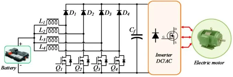
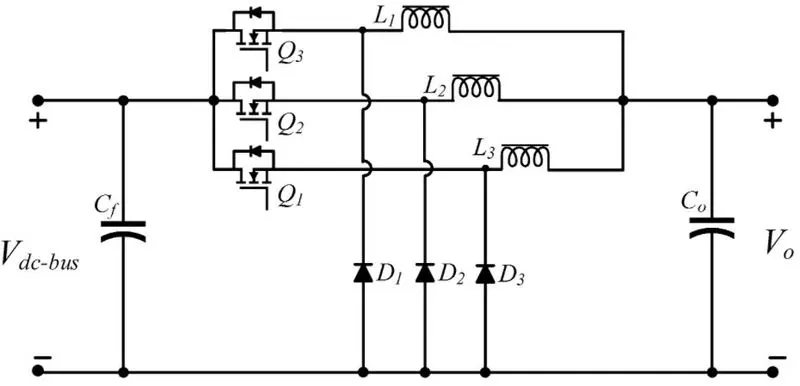
The Interleaved 4-Phase boost DC-DC converter (IBC) topology allows minimizing the input current ripples and output voltage ripples; it steps up voltage ratio approximately above four times . In this converter, four identical levels are introduced with four inductances (L1, L2, L3, and L4); all these inductors have a separate magnetic core. Successive phase shifting of the power switching devices is fixed by the ratio of switching period (T) and the number of Phases (N).
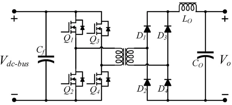
6. Phase-Shift Full-Bridge Converter -
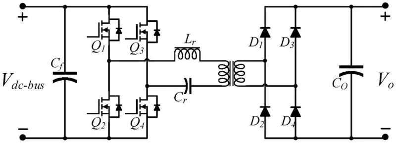
The Phase-shift full-bridge (PSFB) converter is the most popular converter used in high-power applications. PSFB converters have several desirable features such as soft-switching for the primary switches, simple control method, and low current stress on devices. However, PSFB converters have some drawbacks such as high-circulating current in the freewheeling interval and high voltage stress on the rectifier bridge.
B. AC - DC converters
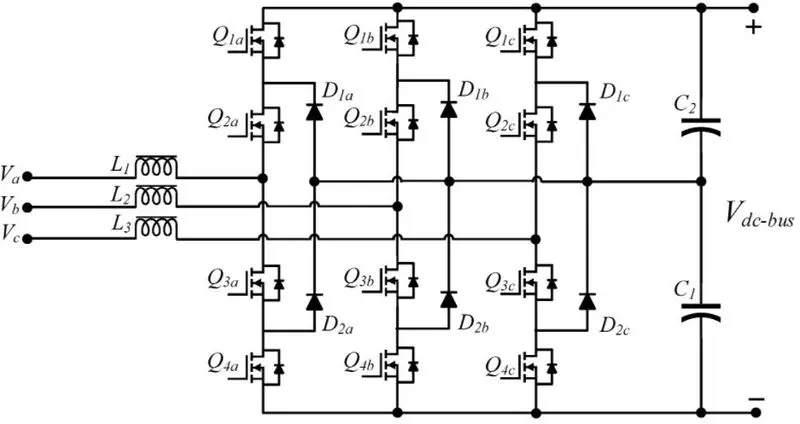
1. Three-Level Three-Phase NPC Converter -
The three-level three-phase NPC converter offers high-power capacity and flexible ways for connecting the input sources . It is also able to produce a five-level output voltage in comparison to the VSI converter. This results in a lower dv/dt rating, a smaller filtering requirement, and a better current performance. However, the NPC converter has an inherent issue, which is the imbalanced power between the positive and negative DC-bus; this imbalanced power can lead to producing an inferior grid-side current that can create instability regarding the grid.
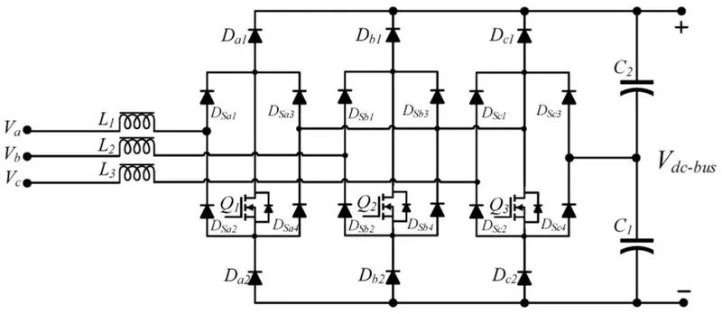
2.Three-Phase Vienna Rectifier-
The three-phase Vienna rectifier has operating principles similar to the three-phase bridgeless boost converter but it uses fewer active switches. The reduction in the number of switches helps to minimize the losses of reverse recovery currents, making it suitable for fast charging. Vienna rectifier is controlled based on regulations of the high-frequency PWM. A critical advantage of this topology is that it exhibits a neutral-connection free. Also, the dead-time problem of the switches can be removed thanks to the diodes taking commutation as soon as the switches turn-off. However, this converter requires a high voltage on the output side. Since one of the three main switches (Q1, Q2 and Q3)">Q1, Q2 and Q3) remains turned off at all times, this results in the minimum voltage over each filter capacitor (C1 or C2">C1 or C2) being the peak input line-to-line voltage. Thus, the minimum boost voltage required for this converter is twice the line-to-line voltage.
2. An Electric Vehicle's powertrain with 72V battery pack in shown in the diagram below. The duty ratio for acceleration operation is 'd1' and for the braking operation the duty ratio is 'd2'. The other parameters of the electric vehicle is given as, Motor and Controller Parameters: Rated Armature voltage= 72 Rated armature current= 400 A Ra= 0.5Ω, KΦ= 0.7 Volt second Chopper Switching frequency= 400 Hz. What is EV steady state speed if duty cycle is 70%?
Given :
Rated Armature voltage= 72 V
Rated armature current= 400 A
Ra= 0.5Ω, KΦ= 0.7 Volt second
Chopper Switching frequency= 400 Hz.
The Vehicle Speed - Torque characteristics are given by the equation below,

Solution :
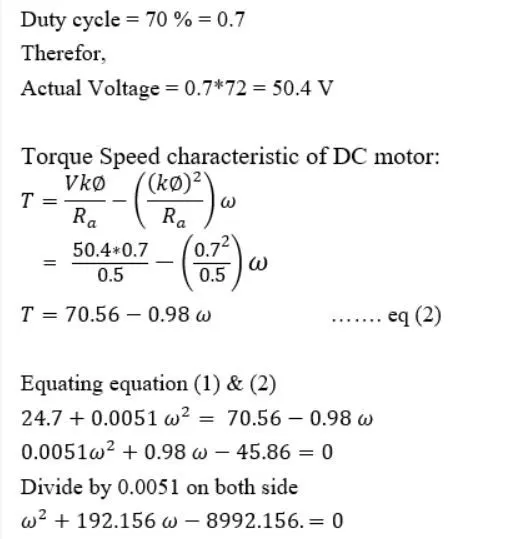
Thus the EV steady state speed at 70 % duty cycle is ω = 38.91 rad/s.
3. Review on Induction Versus DC brushless motors by Wally Rippel, Tesla .
- In this blog published by Wally Rippel, Principal Power Electronics Engineer, Tesla discusses key differences between the DC induction motor and Induction motor. It explain the basic construction of these motors with their positives and negatives.
- In case of DC brushles mototr, permanent magnets are used which produces a rotating magneti field. This magnetic field when induces a current in the conductor. This current results in force generation in the rotor and this results in rotation of the rotor.
- Whereas in case of induction motor, the current is supplied to the stator which results in the generation of emf, when this magnetic field is cut by the rotor which is generally squirrel cage type, this results in current induced in the rotor. Unlike the DC motor, the rotor consists of conductor plates and placed in a cage - like structure. This also consists of bars aroun them in which current gets induced and rotor starts rotating.
- One of the main differences in that much less rotor heat is generated with the DC brushless drive. Rotor cooling is easier and peak point efficiency is generally higher for this drive. It is mentioned that the DC brushless motor can drive at unit power factor. Whereas the best power factor for induction drive is about 85%.
- In case of DC brushless motor, the strength of the magnetic field is adjustable. When at low speed the maximum torque is required magnetic field should be maximum, i.e. inverter and motor current maintained at their lowest optimize efficiency. Whereas there is no such adjustment in case of induction motor.
- As machine size grows, magnetic losses increases proportionally and part load efficieny drops. In case of induction motor, as machine size grows, losses do not necessarily grow.
- However, the speed control of induction motor depends upon the frequency input, which is difficult to control.
- The construction of DC brushless motor is costly compared with an induction motor, due to use of permanent magnets.