Types of Power Convertors and EV Calculating steady state speed
AIM :
- Calculate the EV steady state speed if duty cycle is 70%
- Types of power converter circuits are employed in electric and hybrid electric vehicle
- Author perspective of Inductive vs DC Brushless motors by Wally Rippel
1, Calculate the EV steady state speed if duty cycle is 70% :
%To calculate the EV steady state speed if duty cycle is 70%
clear all
close all
clc
%Given parameters
V_battery = 72; % Rated Armature Voltage
I = 400; %Rated Armature Current
Ra = 0.5;%Armature Resistance
d = 0.7; %Duty cycle
K = 0.7; %Mottor Constant
V = V_battery*d

%Given T_veh= 24.7+0.0051w^2
% We know
% T_motor = (V*K)/Ra - (K^2 * w)/Ra
%Equating both

% 24.7+0.0051w^2 = 50.4*0.7/0.5 - (0.7^2 * w)/0.5
% 0.0051w^2 - 0.98w - 45.86 = 0

A = [0.0051 -0.98 -45.86];
R = roots(A)
From solving we get the roots as,
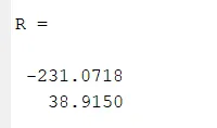
Therefore excluding the negative value, we take the value 38.915
Therefore w = 38.915 rad/s
2, Types of power converter circuits are employed in electric and hybrid electric vehicle :
Depending on the type of function performed, power electronic converters are categorized into following types.
- AC to DC = Rectifier: It converts AC to unipolar (DC) current
- DC to AC = Inverter: It converts DC to AC of desired frequency and voltage
- DC to DC = Chopper: It converts constant to variable DC or variable DC to constant DC
- AC to AC = Cycloconverter, Matrix converter: It converts AC of desired frequency and/or desired voltage magnitude from a line AC supply.
AC to DC Converters or Rectifiers
An AC to DC converter is also called a rectifier, which converts AC supply from main lines to DC supply for the load. The essential components in this rectifier include transformer, switching unit, filter and a control block. Here, the transformer adjusts the primary AC source supply to the input of rectifier stage. Usually it is a step-down transformer that reduces the supply voltage to a circuit operating range. The rectifier converts the low voltage AC supply into DC supply.
It comprises diode and/or thyristors based on type of rectifier. The output of the rectifier is of pulsed DC and hence it is filtered using filter circuit, which is usually made with a capacitor or a choke. The control block controls the firing angle of thyristors in case of phase controlled rectifiers. Since the diode is not a controllable device, control block is not needed in case of diode rectifiers.
DC to DC Converters
A DC chopper is a static device that converts a fixed input DC voltage to variable DC output or a fixed DC output of different magnitude (which can be lower or higher) than input value. The chopper circuit is connected between DC input source and DC load. This chopper consists of power electronic switching devices such as thyristors which are connected in such a way that they produce required DC voltage to the load.
The output voltage is controlled by adjusting ON time of the thyristor (or switch) which turn changes the width of DC voltage pulse at the output. This method of switching is called as pulse width modulation (PWM) control. The output of the chopper can be less or greater than the input and also it can be fixed or variable. These can be unidirectional or bidirectional devices based on the application it is intended for.
DC choppers are mainly used in DC drives, i.e., electric vehicles and hybrid electric vehicles.
AC to AC Converters
AC/AC converters connect an AC source to AC loads by controlling amount of power supplied to the load. This converter converts the AC voltage at one level to the other by varying its magnitude as well as frequency of the supply voltage.
These are used in different types of applications including uninterrupted power supplies, high power AC to AC transmission, adjustable speed drives, renewable energy conversion systems and aircraft converter systems.
DC to AC Converters or Inverters
These converters are connected between DC source of fixed input, and variable AC load. Most commonly, these DC to AC converters are called as inverters. An inverter is a static device that converts fixed DC supply voltage to variable AC voltage.
This conversion from DC to AC along with variable supply is produced by varying the triggering angle to the thyristors. Most of the thyristors used in inverters are employed with forced commutation technique. These can be single phase or three phase inverter depending on the supply voltage. These converters are mainly divided into two groups. One is PWM based inverters and other multilevel inverters.
Further, these are classified voltage source inverter and current source inverter. Each type is subdivided into different types such as PWM, SVPWM, etc. Multilevel inverters are more popular in industrial applications.
3, Author perspective of Inductive vs DC Brushless motors by Wally Rippel
- Less rotor heat is generated with the DC brushless drive. Rotor cooling is easier and peak point efficiency is generally higher for this drive.
- The DC brushless drive can also operate at unity power factor, whereas the best power factor for the induction drive is about 85 percent. This means that the peak point energy efficiency for a DC brushless drive will typically be a few percentage points higher than for an induction drive.
- n an ideal brushless drive, the strength of the magnetic field produced by the permanent magnets would be adjustable. When maximum torque is required, especially at low speeds, the magnetic field strength (B) should be maximum – so that inverter and motor currents are maintained at their lowest possible values. This minimizes the I² R (current² resistance) losses and thereby optimizes efficiency.
- Induction machines have no magnets and B fields are “adjustable,” since B is proportionate to V/f (voltage to frequency). This means that at light loads the inverter can reduce voltage such that magnetic losses are reduced and efficiency is maximized.
- Induction machines are more difficult to control. The control laws are more complex and difficult to understand. Achieving stability over the entire torque-speed range and over temperature is more difficult with induction than with DC brushless. This means added development costs, but likely little or no recurring costs.