Understanding the EV Drivetrain
1. Which types of power converter circuits are employed in an electric and hybrid electric vehicle?
The main components of an electric vehicle are a DC-AC inverter, DC-DC converter, battery, and an electric motor.
There are major power electronic units in the general configuration
1. DC-DC converter
These are classified into uni-directional and bi-directional converters.
- Uni-directional DC-DC converters cater to various onboard loads such as sensors, controls, entertainment, utility, and safety equipment. They are also used in DC motor drives and electric traction.
- Bi-directional DC-DC converters find applications in places where battery charging, regenerative braking, and backup power are required. During regenerative braking, the power flows back to the low voltage bus to recharge the battery. As a backup power system, the bidirectional DC-DC converter facilitates the safe operation of the vehicle when ICEs or electric drives fail to drive the motor. Due to the aforementioned reasons, high power bi-directional DC-DC converters have gained a lot of importance in the recent past.
The converter topologies are classified as:
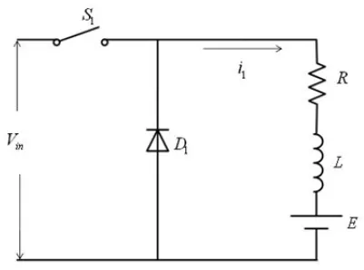
- Buck Converter: In the figure shown below, a buck converter is shown. The buck converter is a step-down converter and produces a lower average output voltage than the dc input voltage.
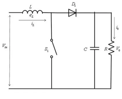
- Boost converter: In the figure shown below, a boost converter is shown. The output voltage is always greater than the input voltage.
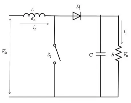
- Buck-Boost converter: In the figure shown below, a buck-boost converter is shown. The output voltage can be either higher or lower than the input voltage.
The main dc-dc converter changes dc power from an on-board 200-800V high voltage battery into lower dc voltages (48V or 12V) to power headlights, interior lights, wiper and window motors, fans, pumps, and many other systems within electric vehicles (EV), and hybrid electric vehicles (HEV). This high voltage to low voltage (HV-LV) dc-dc converter is often referred to as an auxiliary dc-dc, or Auxiliary Power Module (APM). Isolation is critical for separating the control systems from high-voltage domains.
2. DC-AC inverter
An inverter is a device that converts DC power from the battery to AC power used in an electric vehicle motor. The inverter can change the speed at which the motor rotates by adjusting the frequency of the alternating current.
The use of Inverters can increase or decrease the power or torque of the motor by adjusting the amplitude of the signal. It plays a significant role in capturing energy from regenerative braking and feeding it back to the battery.
The key component is that it has a direct impact on on-road performance, driving range, and reliability of the vehicle also as a consequence of their weight and size. The output voltage waveform of ideal inverters should be sinusoidal. However, the waveform of practical inverters is non-sinusoidal and contains certain harmonics.
2. An Electric Vehicle's powertrain with a 72V battery pack is shown in the diagram below. The duty ratio for acceleration operation is 'd1' and for the braking operation the duty ratio is 'd2'.
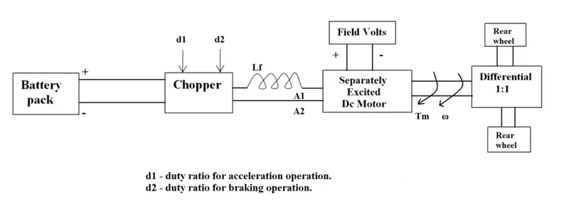
The other parameters of the electric vehicle are given below,
Motor and Controller Parameters:
Rated Armature voltage= 72 V
Rated armature current= 400 A
Ra= 0.5Ω, KΦ= 0.7 Volt second
Chopper Switching frequency= 400 Hz
The vehicle speed-torque characteristics are given by the below equation

What is EV steady-state speed if the duty cycle is 70%?
As given let us consider the equation, `Tv=24.7+ (0.0051)*w^2` .......... (1)
We need to find the EV steady-state speed when the duty cycle is at 70%.
So, the torque required by the motor is equal to the torque required by the vehicle at the steady-state or the operating point.
The rated armature voltage at the given duty cycle = `0.7 xx 72 = 50.4`
The motor constant, `kphi = 0.7 Vs`
The speed-torque characteristics for a motor are defined by the equation given below.
`w = (Va)/(kphi) - (RaTv)/(kphi^2)`
Substituting the above-given parameters in the equation, we get,
`w= 72-1.020Tv`
Re-arranging the terms in the above equation to get the torque equation.
`Tv=70.6-0.98w` .......... (2)
Now equating (1) and (2), we get
`24.7+0.0051*w^2=70.6 - 0.98*w`
`0.0051*w^2+0.98*w-46=0`
This is now a quadratic equation, the roots of this equation once it is solved will give us the steady-state speed.
The roots are: `w=-231.173` rad/s and `w=39.016`
Hence the required EV steady-state speed at a 70% duty cycle is 39.016 rad/s.
3. Refer to the blog on the topic: Induction Versus DC brushless motors by Wally Rippel, Tesla.
Explain in brief about author’s perspective.
The author Wally Ripple, the principal power electronics engineer at Tesla begins by stating that there is no one best engine type, rather there are different types of engine to suit personal requirements, such as price and performance. He also discusses how the technologies changes with time, i.e., Lead-acid batteries being replaced by Lithium and DC motors being replaced by either a DC brushless or an induction motor. After this introduction, he states that in the years to come the DC brushless and induction motor will "duke it out" for many years to come. With this, he continues to explain the working of both DC brushless and induction motors with all its pros and cons.
He explains that with brushless machines, the rotor includes two or more permanent magnets that generate a DC magnetic field (as seen from the vantage point of the rotor). In turn, this magnetic field enters the stator core (a core made up of thin, stacked laminations) and interacts with currents flowing within the windings to produce a torque interaction between the rotor and stator. As the rotor rotates, the magnitude and polarity of the stator currents must be continuously varied – and in just the right way - such that the torque remains constant and the conversion of electrical to mechanical energy is optimally efficient. The device that provides this current control is called an inverter. Without it, brushless motors are useless motors. Unlike the DC brushless rotor, the induction rotor has no magnets – just stacked steel laminations with buried peripheral conductors that form a “shorted structure.” Currents flowing in the stator windings produce a rotating magnetic field that enters the rotor. In turn, the frequency of this magnetic field as “seen” by the rotor is equal to the difference between the applied electrical frequency and the rotational “frequency” of the rotor itself. Accordingly, an induced voltage exists across the shorted structure that is proportionate to this speed difference between the rotor and electrical frequency. In response to this voltage, currents are produced within the rotor conductors that are approximately proportionate to the voltage, hence the speed difference. Finally, these currents interact with the original magnetic field to produce forces – a component of which is the desired rotor torque. When a 3-phase induction motor is connected to utility type 3-phase power, torque is produced at the outset; the motor has the ability to start under load. No inverter is needed. The author explains how a brushless DC motor would require an external inverter and the induction motor would not require one.
Next, the author looks into the difference between both types. One main difference would be that less rotor heat is generated in the DC brushless motor and hence the peak point efficiency of this type would be generally a few point percentages higher than the induction type. He also states that even though the peak efficiency of a DC brushless is more, it need not be the case for average efficiency. He explains that this is because there is no easy way to change the magnetic field strength in a DC brushless without causing eddy and hysteresis losses, but in an induction motor type, this is not the case, as there are no permanent magnets, it's easier to change the magnetic field strength in such a way that the magnetic losses are reduced and efficiency is maximized. With DC brushless, as machine size grows, the magnetic losses increase proportionately and part load efficiency drops. With induction, as machine size grows, losses do not necessarily grow. Thus, induction drives may be the favored approach where high-performance is desired; peak efficiency will be a little less than with DC brushless, but average efficiency may actually be better.
He also explains that the induction motor has a cost advantage over DC brushless due to the requirement of permanent magnets in the latter type. Also, due to the field weakening capabilities of induction machines, inverter ratings and costs appear to be lower, especially for high-performance drives. Since spinning induction machines produce little or no voltage when de-excited, they are easier to protect. In the end, the author teases the fact that it is difficult to control an induction motor as the control laws are more complex and difficult to understand.
At the end of the blog, he concludes that DC brushless drives will likely continue to dominate in the hybrid and coming plug-in hybrid markets, and that induction drives will likely maintain dominance for the high-performance pure electrics. The fact that so much of the hardware is common for both drives could mean that we will see induction and DC brushless live and work side by side during the coming golden era of hybrid and electric vehicles.