Week-6 Challenge: EV Drivetrain
- POWER CONVERTER:
A Converter is an electrical circuit which accepts a DC input and generates a DC output of a different voltage ,usually achieved by high frequency switching action employing inductive and capacitive filter elements.A power convertor is an electrical circuit that changes the electrical energy from one form into the desired form optimized for the specific load.A convertor may do one or more function and give an output that differs from the input.It is used to increase or decrease the magnitude of the input voltage,invert polarity,or produce several output voltages of either the same polarity with the input or different polarity,or mixed polarities such as in computer power supply unit.
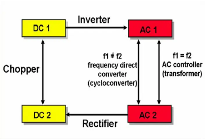
The convertor acts as the link between the power source and power supply output.There are several kinds of convertors based on the source input voltage and the output voltage and these falls into four categories namely the AC to DC converter known as rectifier,the AC to AC clycloconverter or frequency changer,the DC to DC voltage or current converter,and the DC to AC inverter.
- DC to DC CONVERTOR(Chopper):
A DC to DC convertor is an electronic circuit or electromechanical device that converts a source of direct current (DC) from one voltage level to another.It is a type of electric power convertor,power level ranges from very low(small batteries) to very high(high-voltage power transmission).DC-DC Converter in an electric vehicle may be classified into unidirectional and bidirectional converters.Unidirectional DC-DC converters cater to various onboard loads such as sensors,controls enterainment,utility and safety equipments.They are also used in DCmotor drives and electric traction.Bi-directional DC-DC converter find application in place where charging ,regenerative braking and backup power are required.The power flow in a bidirectional converter is usually from a low voltage end such as a battery or a supercapacitor to a high voltage side and is refered to as boost operation.During Regenerative braking,the power flows back to the low voltage bus to recharge the battery(buck mode).As a backup power system,the bidirectional DC-DC converter facilitates the safe operation of the vehicle when electric drives fail to drive the motor.While DC-DC converter can be based on a number of different designs,the underlying function remains the same.In electric vehicles which use a DC motor ,running the motor can use upto three times the voltage provided by the battery.With the help of right converter ,we can bridge this gap without having a possibility to a larger,prohibitively heavy battery.
The converter topologies are classified as :
BUCK CONVERTER(Step-Down Regulators):
The Buck converter is a step down converter and produces lower average output voltage than the DC input voltage.
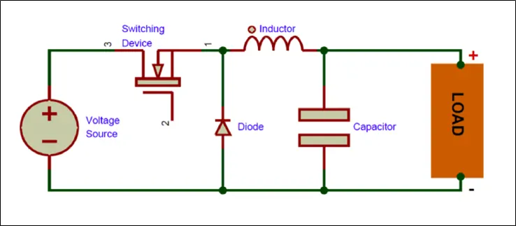
The step-down or buck switching regulator (or chopper) is shown in figure . The essential components are an electronic switch with an associated drive circuit, a diode and an inductor. In figure the switch is on, and the current flows through the inductor and the load. The inductor produces a back EMF, making the current gradually rise. The switch is then turned off. The stored energy in the inductor keeps the current flowing through the load, using the diode. The different currents flowing during each part of this on–off cycle . The voltage across the load can be further smoothed using capacitors if needed.
BOOST CONVERTER(Step-Up Regulators):
The Boost converter is a step up converter and produces voltage which is always greater than the input voltage.
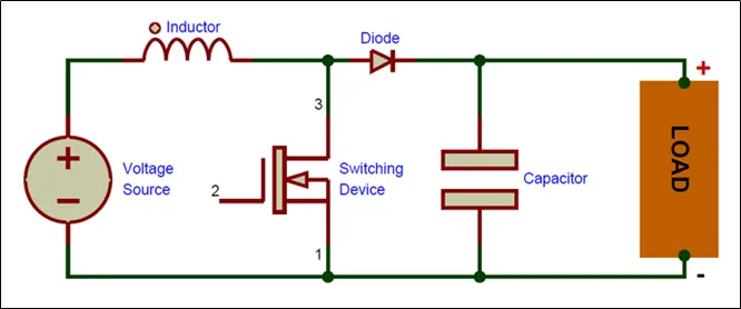
when switch is on, and an electric current is building up in the inductor.The load is supplied by the capacitor discharging by assuming some charge is in the capacitor.The Diode prevents the charge from the capacitor flowing back through the switch.When switch is in off condition, the inductor voltage rises sharply because the current is falling.As soon as the voltage rises above that of the capacitor (plus about 0.6 V for the diode) the current will flow through the diode, and charge up the capacitor and flow through the load. This will continue as long as there is still energy in the inductor. The switch is then closed again, and the inductor re-energised while the capacitor supplies the load.
BUCK-BOOST CONVERTER:
The output voltage can be either higher or lower than the input voltage.
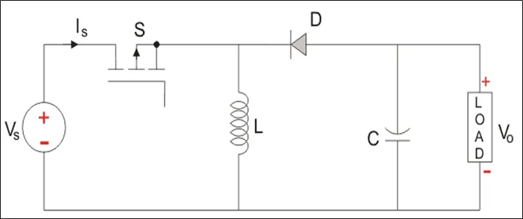
- while in the On-state, the input voltage source is directly connected to the inductor . This results in accumulating energy in inductor. In this stage, the capacitor supplies energy to the output load.
- while in the Off-state, the inductor is connected to the output load and capacitor, so energy is transferred from inductor to capacitor and load.
- DC-AC converter(Inverters):
A Power inverter is a power electronic device or circuitry that changes direct current(DC) to alternating current(AC).The input voltage,output voltage and frequency,overall power handling depend on the design of the specific device.The inverter does not produce any power,the power is provided by the DC source.Power inverter are primarily used in electrical power application where high currents and voltages are present.
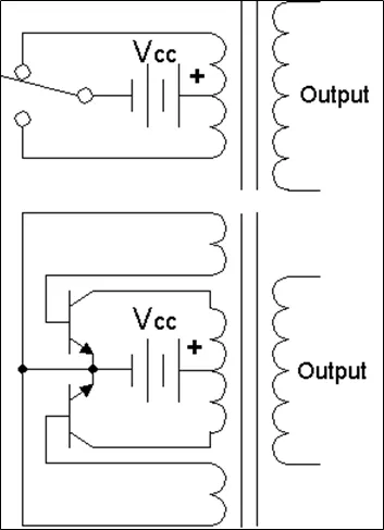
In simple inverter circuit,DC power is connected to a transformer through the centre tap of the primary winding.A switch is rapidly switched back and forth to allow current to flow back to the DC source following two alternate paths through one end of the primary winding and then the other.The alternation of direction of current in the primary winding of the transformer produces alternating current(AC) in the secondary circuit.
The inverter used in electric vehicle can change the speed at which the motor rotates by adjusting the frequency of the alternating current.The use of inverters can increase or decrease the power or torque of the motor by adjusting the amplitude of the signal.It plays a significant role in capturing energy from regenerative braking and feeding it back to the battery.The key component is that it has a direct impact on on-road performance,driving range and reliability of the vehicles also as a consequence of their weight and size.The output voltage waveform of ideal inverters should be sinusoidal.However,the waveform of practical inverters are non-sinusoidal and contain certain harmonics.
- AC-AC CONVERTER:
AC-AC Converter is used for converting the AC waveforms with one particular frequency and magnitude to AC waveform with another frequency at another magnitude.This conversion is mainly required in case of speed controlling machines,for low frequency and variable voltage magnitude applications as well.We know that there are different types of loads that work with different types of power supply like single-phase,three-phase and the supplies can be differentiated based on the voltage and frequency reange also.For speed control of induction motors,AC-AC converters is used majorly.For obtaining a desired AC power supply from the actual power supply,we need some converters called AC-AC converters.
The AC-AC converter can be classified into different types;
- Cyclconverter
- AC-AC converter with DC link
- Matrix converter
- Hybrid Matrix converter
- AC-DC CONVERTER(RECTIFIER):
A rectifier is an electrical device that converts alternating current(AC),which periodically reverses direction,to direct current(DC),which flows in only one direction ,the process is known as rectification,since it straightens the direction of current.In PHEV and EV have an AC-DC converter which supplies electric power from commercial power system to an onboard high-voltage battery,in addition to a DC-DC converter which generates electric power for the accessory.
QUESTION 2:
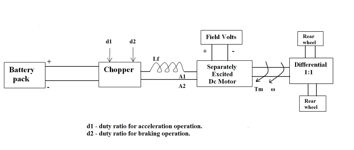
An Electric Vehicle's powertrain with 72V battery pack in shown in the diagram below. The duty ratio for acceleration operation is 'd1' and for the braking operation the duty ratio is 'd2'.
The other parameters of the electric vehicle is given below,
Motor and Controller Parameters:
Rated Armature voltage= 72 V
Rated armature current= 400 A
Ra= 0.5Ω, KΦ= 0.7 Volt second
Chopper Switching frequency= 400 Hz
The vehicle speed-torque characteristics are given by the below equation

What is EV steady state speed if duty cycle is 70%?
>>>>> SOLUTION
Torque -Speed characterstics is given by the equation,
`T =(V*(k_mphi))/R_a -(k_mphi)^2/R_a*omega` .........equation (1)
Output voltage = battery voltage * duty cycle
`V_(op) = V_(bat)*d`
`V_(op) = 72*0.7`
`V_(op) = 50.4` ........volts
substitute in equation (1)
`T =(50.4*0.7)/0.5-(0.7)^2/0.5*omega`
By comparing,
`24.4+0.0051omega^2 = 70.56-0.98omega`
rearraging,
`omega^2+192.15omega-8992.15 = 0`
The above equation is in the quadratic form `aomega^2+bomega+c=0` the roots can be obtained by the equation
`omega_(1,2)= ((-b+sqrt((b)^2-4ac))/(2a))`
`omega= 38.914 (rad)/s`
N = 371.60 RPM
Thus steady state vehicle speed with 0.7 duty cycle is 371.60rpm
- INDUCTION MOTOR VS DC BRUSHLESS MOTOR:
Induction Versus DC brushless motors by Wally Rippel, Tesla
In the above blog author tries to give the advantages and disadvantages of both the motors by comparing side by side,
According to the author ,
| DC BRUSHLESS MOTOR | INDUCTION MOTOR | |
| ROTOR CONSTRUCTION |
Rotor consists of permanent magnet |
Induction rotor doesnot contain magnet just a stacked steel lambination |
| STATOR CONSTRUCTION | Three sets of “distributed windings” that are inserted within the stator core. | Three sets of “distributed windings” that are inserted within the stator core. |
| CONTROL STRATEGY | Inverter is needed to control the stator currents to generate Magnetic field | No inverter is needed,runs directly on 3 phase power supply. |
| SUPPLY | DC | 3 Phase supply |
| TORQUE | DC motor produces no starting torque when directly connected to fixed frequency utility source | When a 3-phase induction motor is connected to utility type 3-phase power, torque is produced at the outset; the motor has the ability to start under load. |
| SPEED | can be varied or controlled by inverter | They are constant speed machines |
| ROTOR HEATING | Less rotor heat is generates and can be effectively cooled | More rotor heat is generated |
| EFFICIENCY | Efficiency is high | Efficiency is comparitively low |
| COST | Permanent magnets are expensive | Their are no magnets hence cheaper |
The author concludes that their is no winner between Induction motor and DC brushless motor,and he states that the DC brushless motor drives are better for hybrid electric vehicles and Induction drives for high performing electric vehicle and he hopes in the future that these two motors can work side by side.