Week 6 Challenge
1.Introduction :-
In Bridge Design Load consideration an important load is "Utility Load". In this challenge we get the effects due to Utility Load.Utility load may be in differents type like Electric pole on bridge , Pipe line for different liquid like water supply , gas Pipe line or petrolium line.Due to these utility load will effect the bridge design.
So here we find out the the resultant due to utility Load with the help of Staad Pro.
2.Aim :-
Here we find out the effects due to given pipe line on the bridge in form of Displacement, Bending moment and Shear force.
3.Given :-
Bridge width -3m
Length -25m
Type of Bridge -Composite
Type of Pipe -DI
Dia of Pipe -700 mm
-200 mm
4.Produre :-
As we know that utility load is working as Point Load Steel bridge. So we need the 2 thing for calculate the Point load on the Secondary Beam of Steel Bridge. Load due to flow liquid in the pipe and second dead load of pipe per unit length.
Let assume that both pipe line carry water supply line so here calculate load due to water and unit weigth of 700 NB DI Pipe and 200mm NB DI from IS code we get the
700 mm DI Pipe - 185.943 Kg or 1.589 Kn
Unit weigth of water for 700mm pipe - 3.846 Kn
Total weigth =5.435Kn
200 mm DI Pipe -45.28 kg or 0.453 Kn
Unit weigth of water for 200mm pipe - 0.314 Kn
Total weigth =0.767Kn
Manual data required calculated now , we need the create the model and apply apply the load and get the result
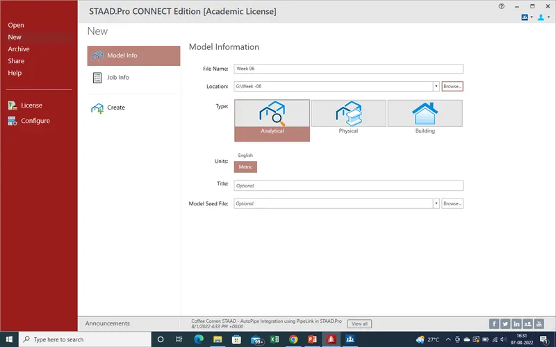
1. Now We find the Results due to Pipe on the bridge. Now same process will be follow as given pic.
First of all select the file location and after that we will select the "Create".
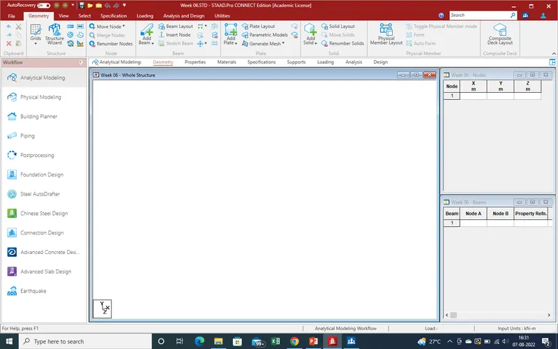
2.As we click on "Create" a new window has been open.Now here we can start modelling for define the loading
3.We start create the node as In Y-Direction.as given distance at side bar
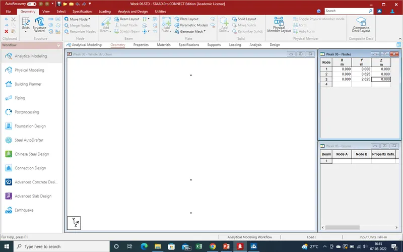
4.Now Create the nodes in Z-Direction as 3m distance as per our given drawing.
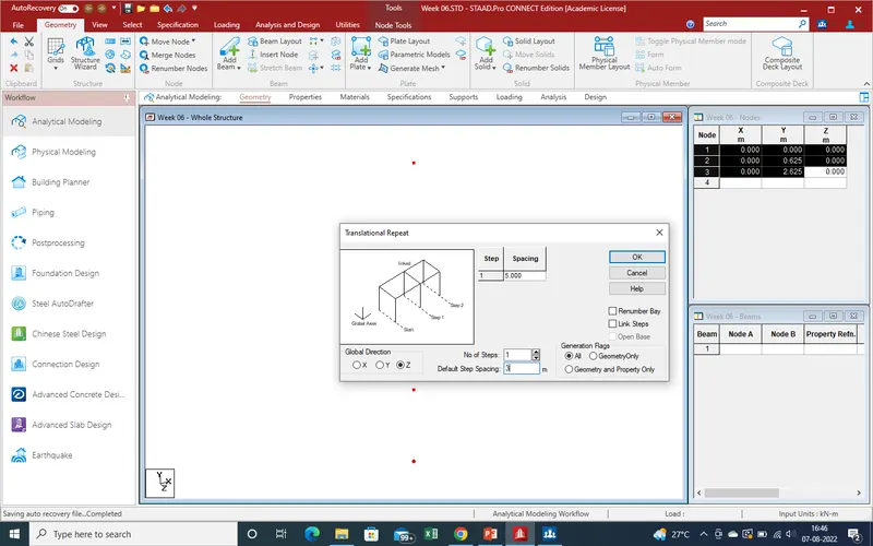
5.With the help of Translation repeat command create the cross section area and get the results as shown in given pic
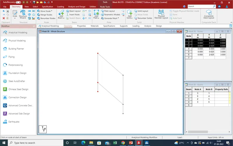
6.The same process has been created in X-direction with the help of traslation Repeat comand for create the frame as given specified distance.
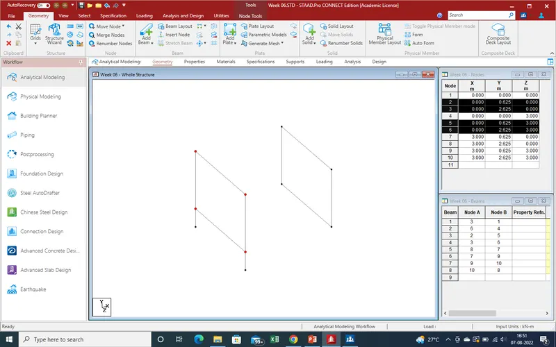
7.As here we can see that no of steps are 6 and spacing are 3m as given in data .
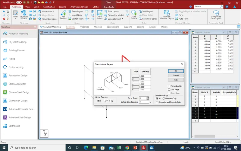
8.Now we get the results as showing in given Pic .
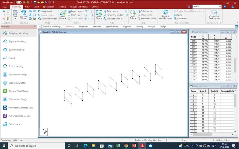
9.Now create the horizontal beam for inter connect the frame as per requirment of model or Data.
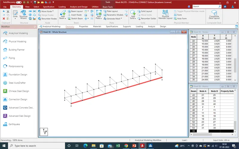
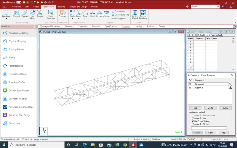
10.Now join the the cross beam with the help of beam command as given data which are given in.
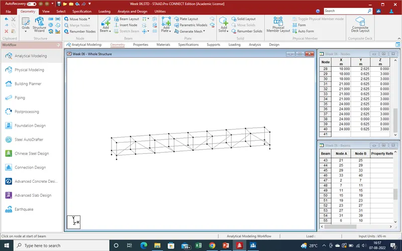
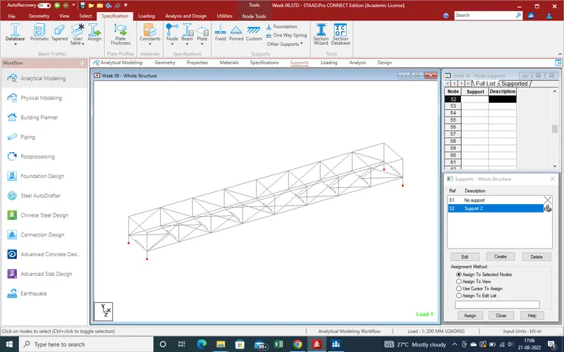
11.Joint the Inclined Beam For Vertical beam as given bridge.
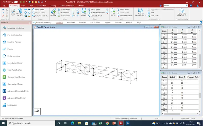
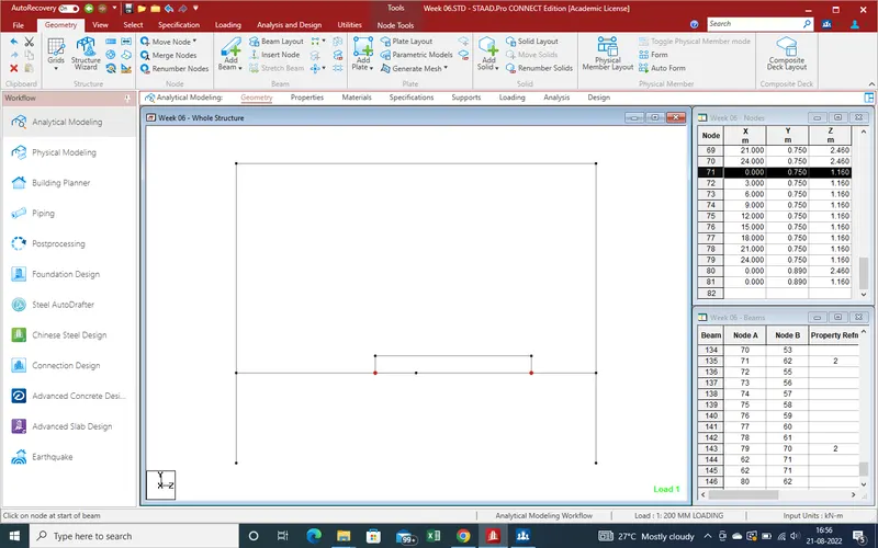
12.We can see in second view of bridge as from top.Select the node for bottom cross,Create the new node at centre of cross beam.
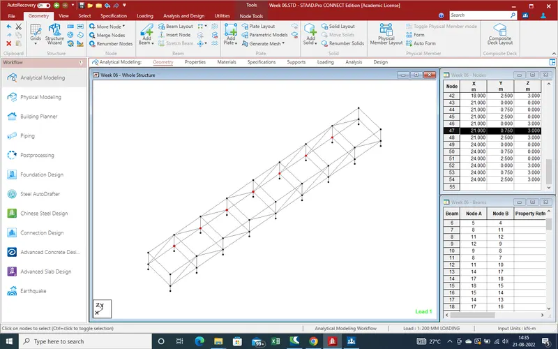
13.Use of translation repeat command create the node for join the cross beam at bottom.
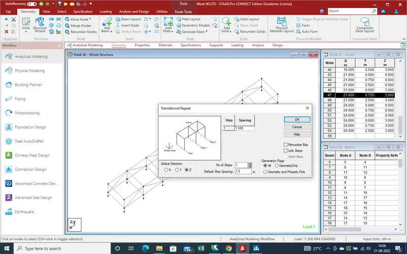
14.Use of "Create Beam" command create the beam as shown in given pic.
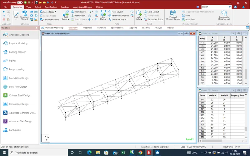
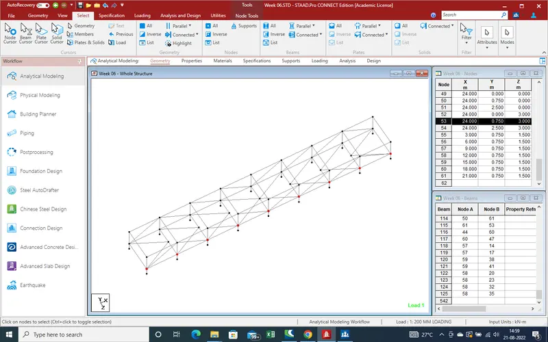
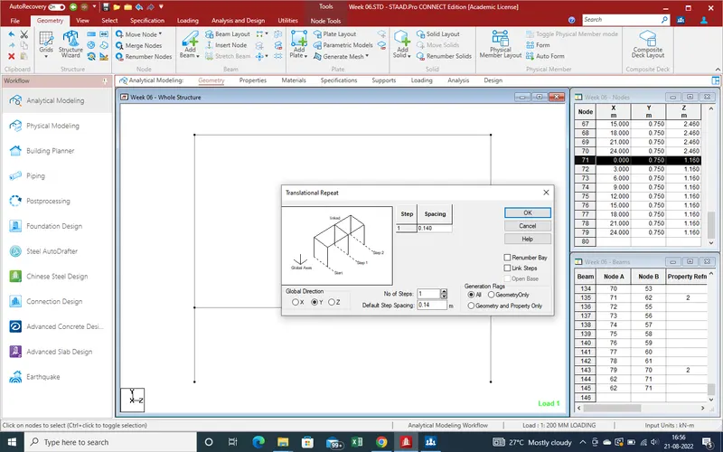
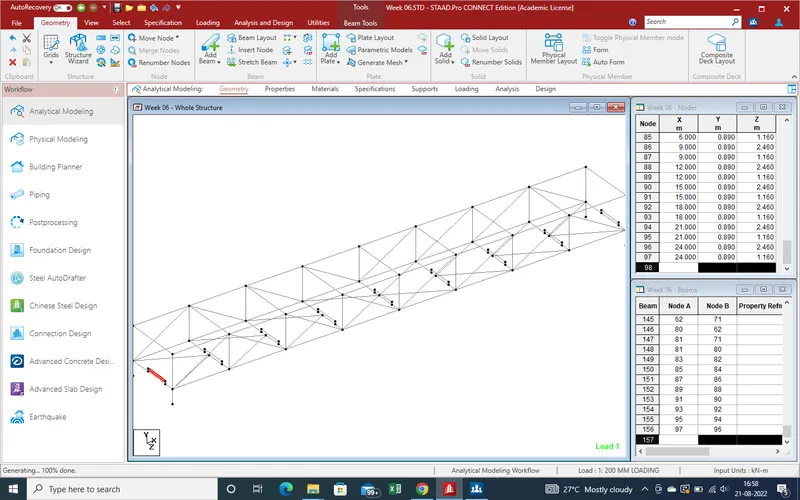
15.Again select the node for translation repeat command for secondary beam on main girder beam.
16.From centre of beam distance is 0.540m is given as given in data .
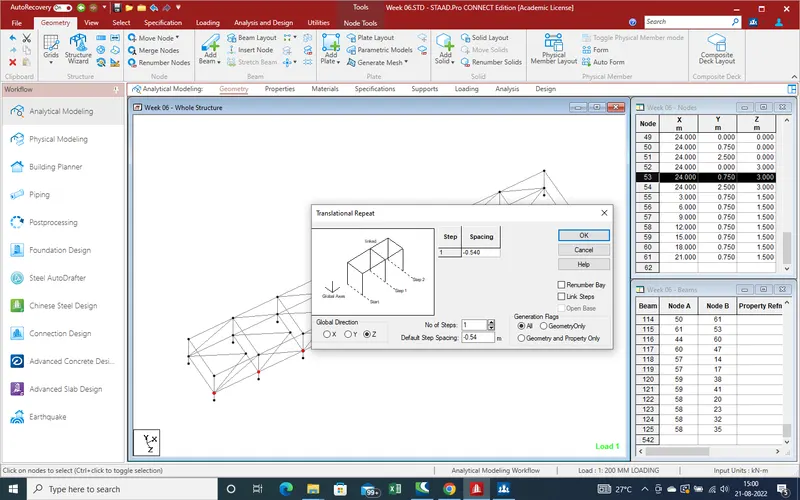
17.Same for next step
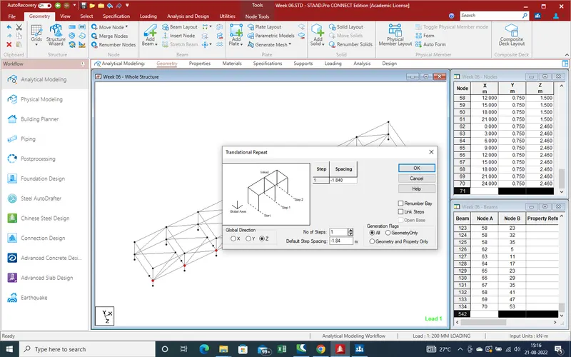
18.Get the node for secondary beam over the main beam for hold the pipe line over the deck .Now same will be second node as showing in given below pic.
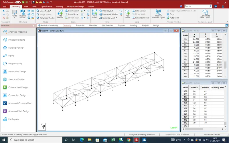
19.Now all modelling work has been done,now need the define the properties for different component of given model
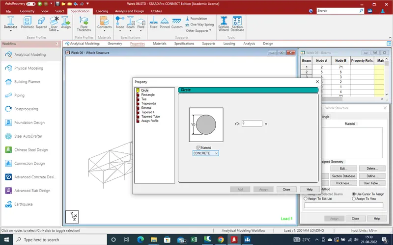
20.As here bridge is steel bridge so go to Data base section as showing pic ,and select the country and select the steel as here rolled steel and coldformed steel. As here am select the rolled steel as use for bride. Again an new window open on main bar
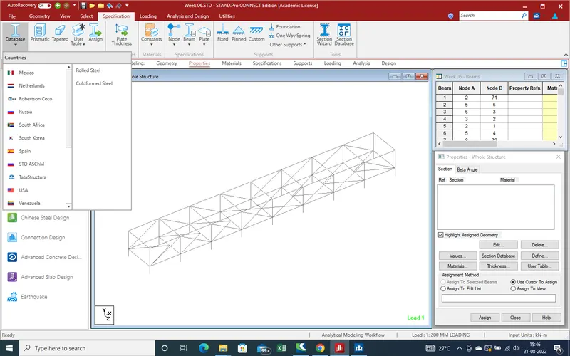
21.Now select the shape for section as required for bridge .
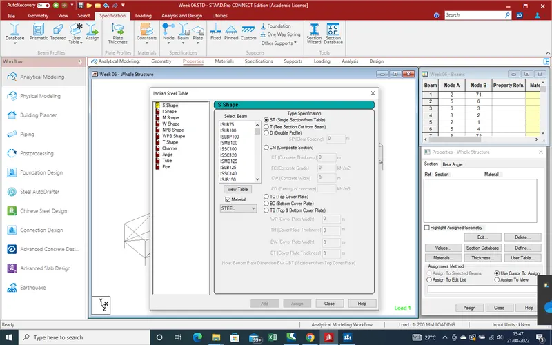
22.As first section is "S" section ISMB -400 with additional Plate at both side. so select the first ISMB 400 and then after top & bottom cover plate. Put the details of cover plate as width 200mm and thickness 16 mm . Bottom plate 368 mm with thickness of 12 mm.
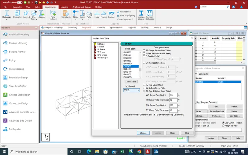
23.Same as next is ISMB 250 mm and click on Add .
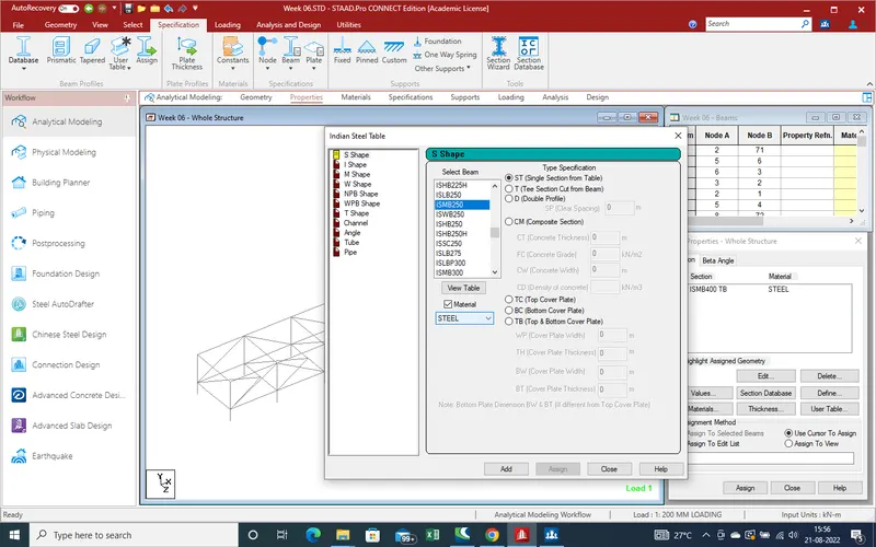
24.Next ISMC 200
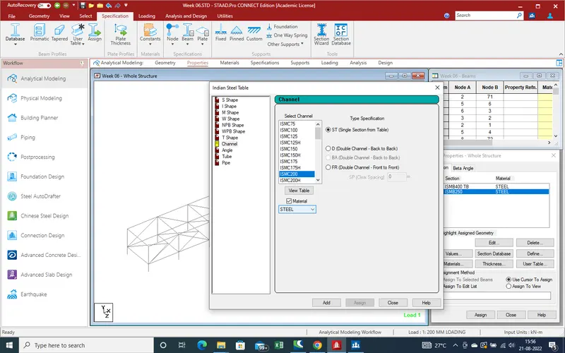
25.ISA 90*90*8 which is back to back so select the spacing between both angle is consider is 0
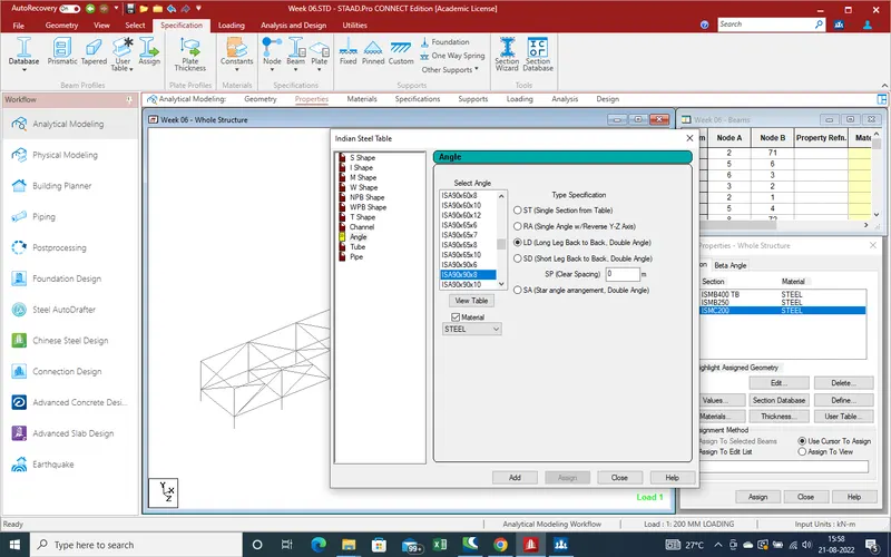
26.ISA 75*75*6
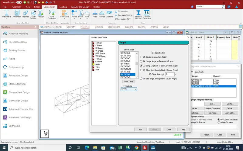
27.ISA 65*65*6
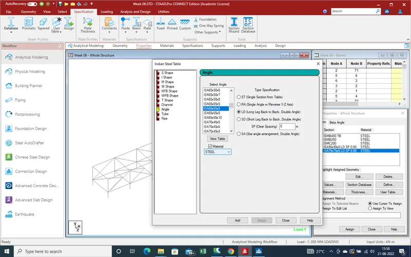
28.ISA 50*50*6
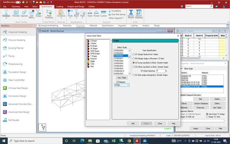
29.ISMC 100
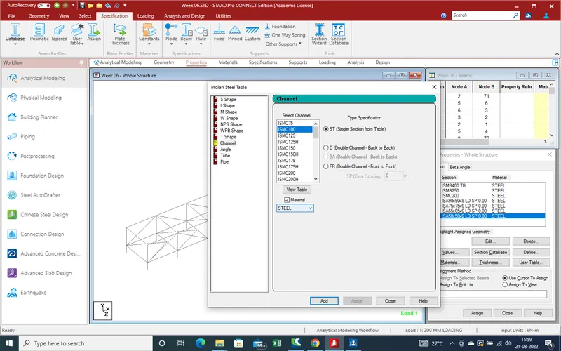
30.Now all Properties has been created. Now next step is apply these properties at apropriate location as given bridge .
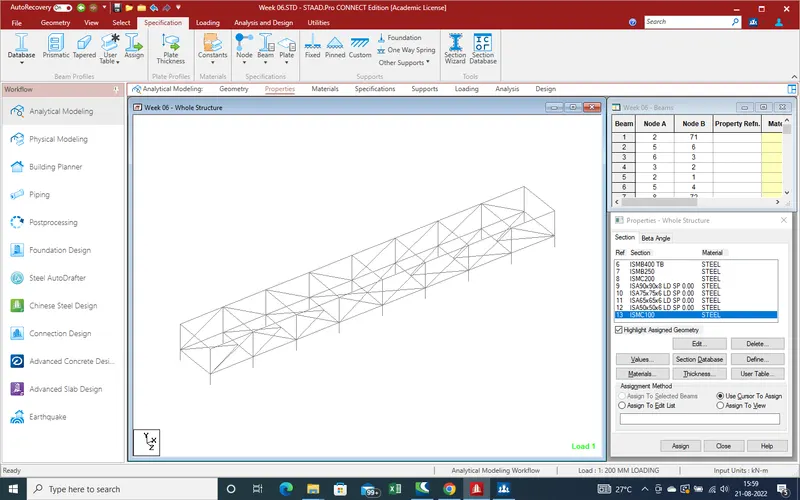
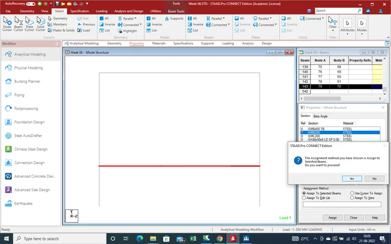
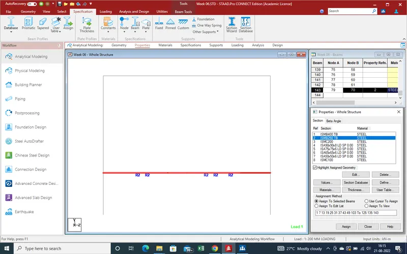
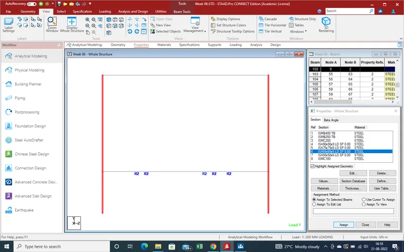
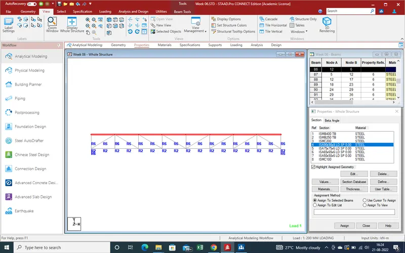
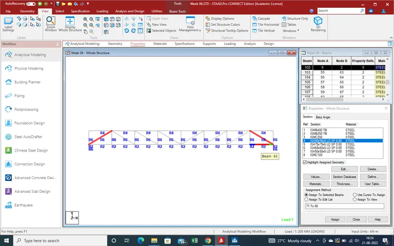
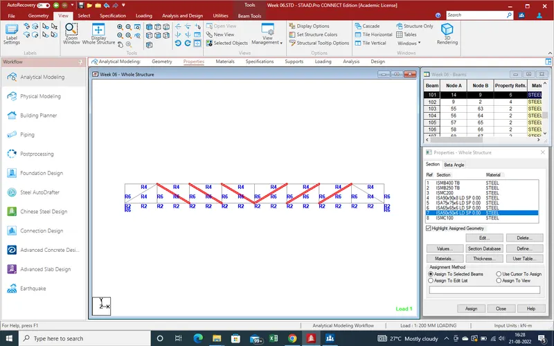
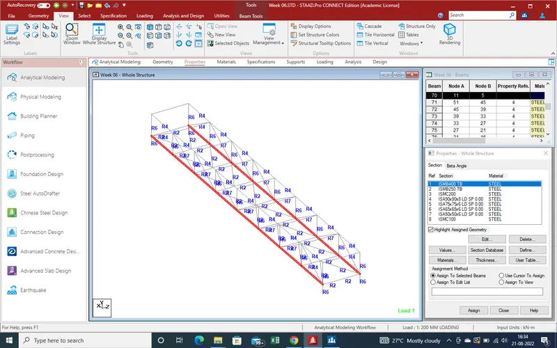
31.At face section for apply the properties as showing in given pic .
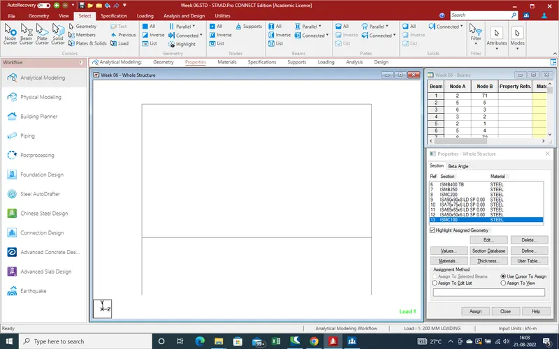
32.as bottom main beam is ISMB -250 mm then select the beam properties and then apply on bottom main cross beam as given in section.
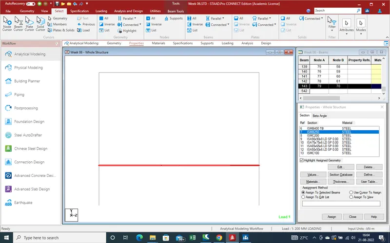
33.After apply all properties ,Need the apply the support reation at end .As here bridge fixed on the pier with help of bolt, so support are apply as fixed support .Now Create the Fixed Support .
34.Select the reaction and after select the node where we need apply the reation as showing in given pic.
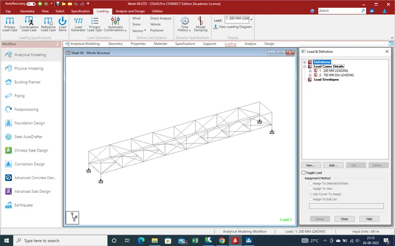
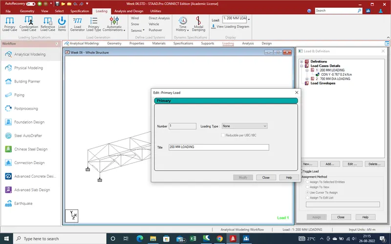
35.Now Apply the Load on bridge due to Pipe with water on the bridge .Here 2 different pipe at different location which work on bridge as point load. as in starting we calculate the point load due to 200mm dia pipe and 700mm dia as .
36.Select the load case as 200mm dia loading and 700mm dia load as showing in given pic .
37.
38.
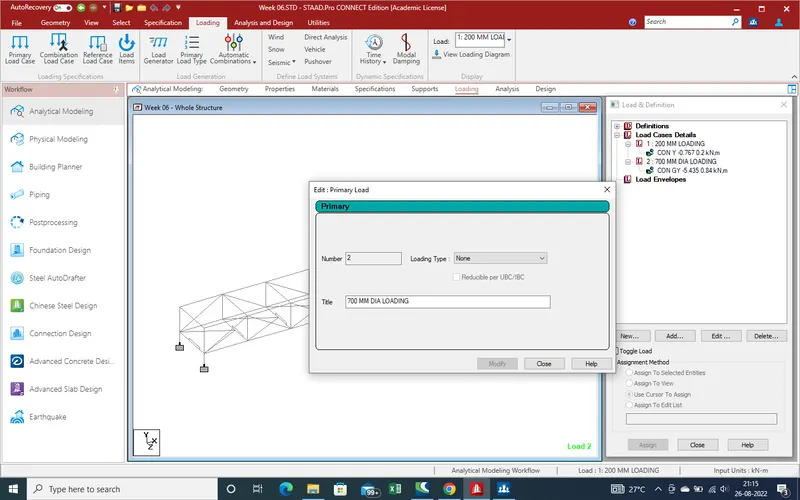
39.Apply the load as calculated in 200mm dia pipe is 0.767 and (-) sign for downward direction and 200 mm distance from face of beam and direction use as globle (Y).
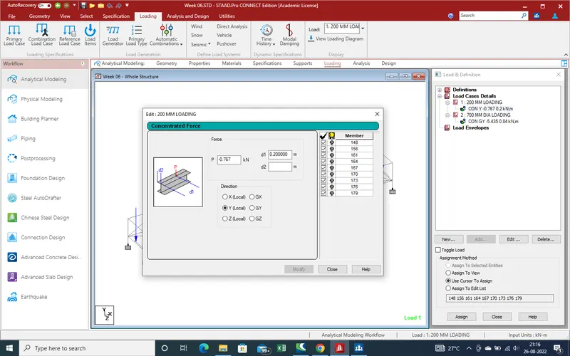
40. Same as for 700mm dia pipe .
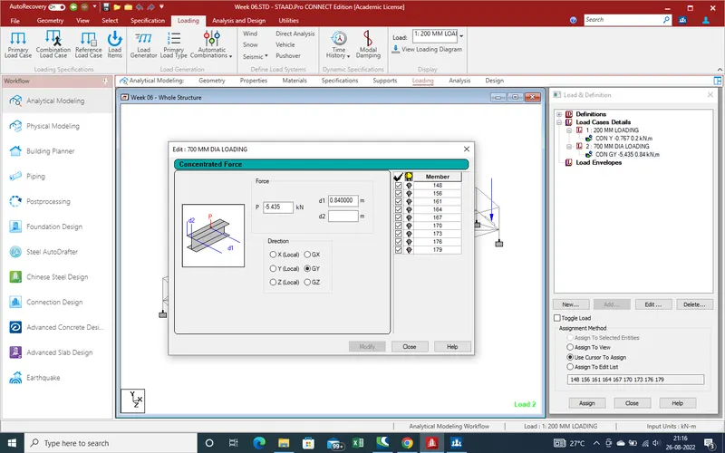
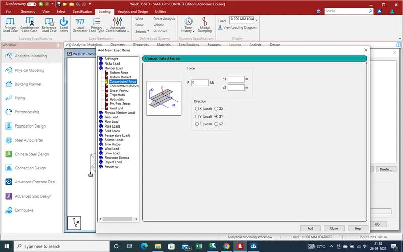
41.Load we use as Nodel load as point load as showing given pic .
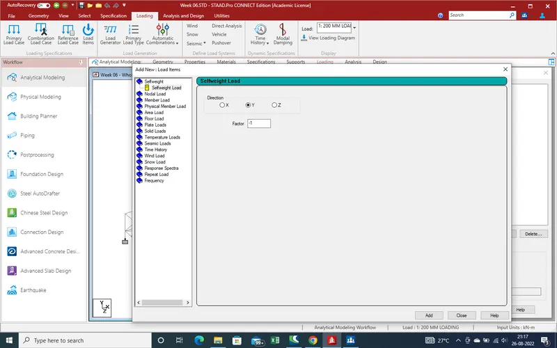
42.
43.Loading showing as given below pic .
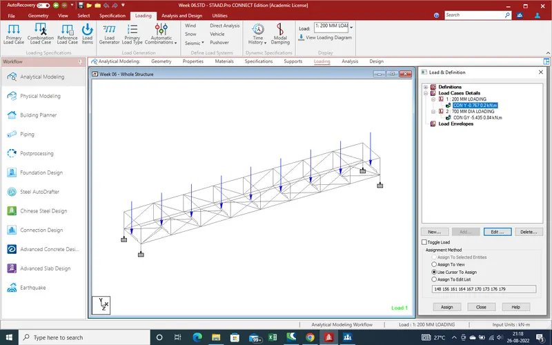
44.700mm dia loading
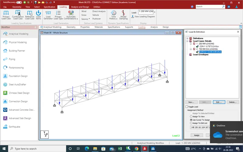
45.Now perform analysis we run the analysis .
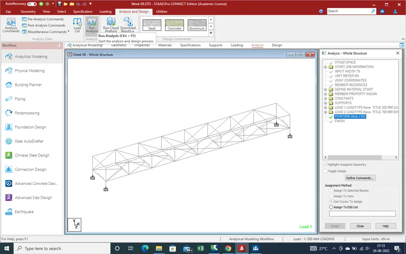
46.As we run the file we get that there is no error so all thing are ok as showing in given below pic.
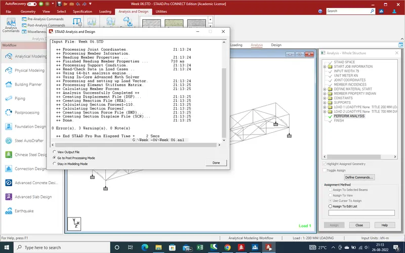
47.With the help of "Post Processing Mode " we get the results due to Pipe on Bridge .
5.Result :-
1.Now we get the result due to pipe loading on bridge .
select the loading for results.
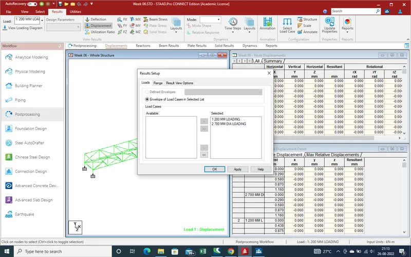
2.Now get the displacement results due to 200 mm dia pipe .
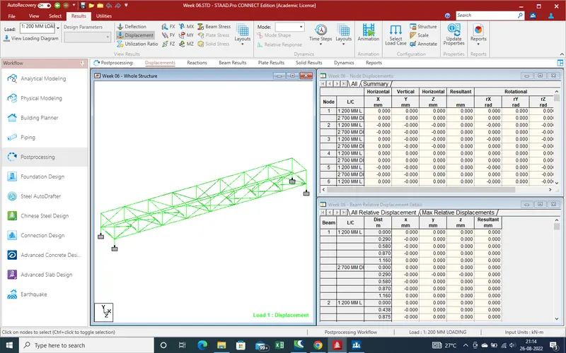
3.Displacement due to 700mm pipe loading .
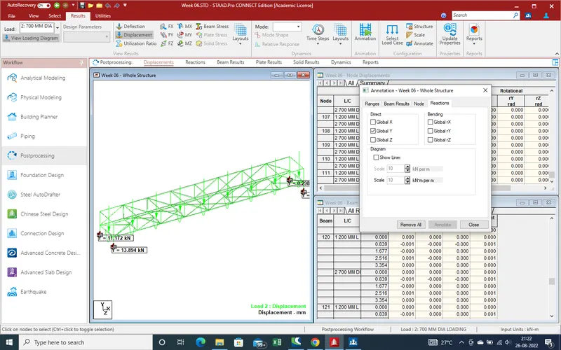
4.Displacement reaction in Y-Direction due to 700mm dia pipe loading
5.Displacement reaction in Z-direction due to 700mm dia pipe.
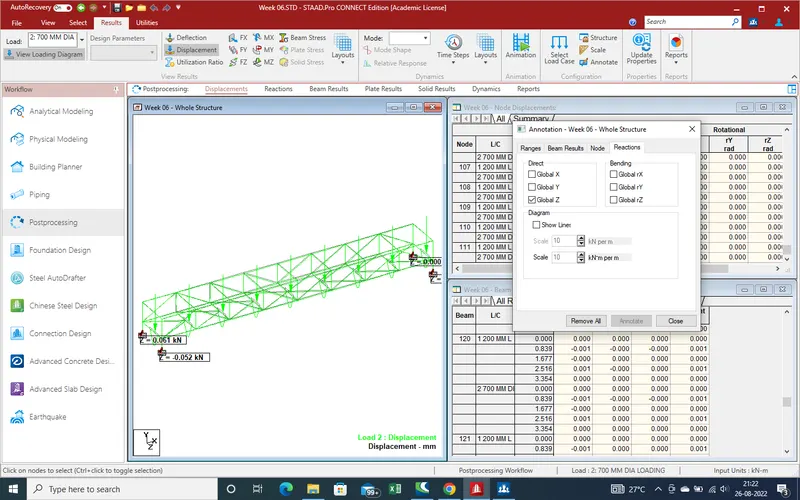
6.Bending displacement in X-direction
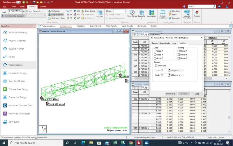
7.Bending Displacemet in Z-direction.
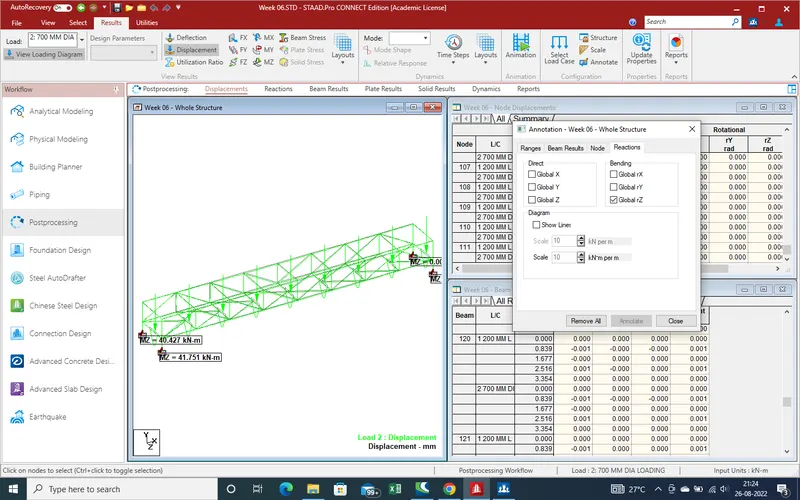
8.Reactions due to moment reaction in Z-direction
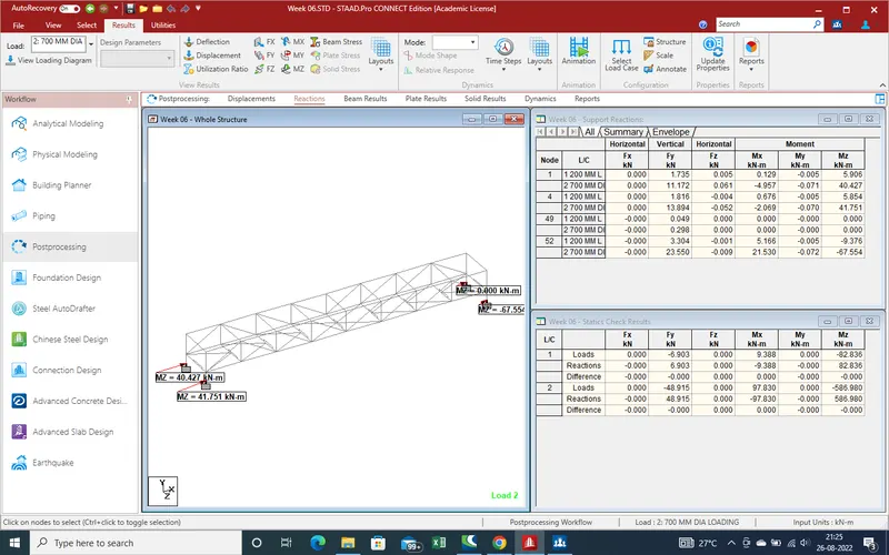
9.
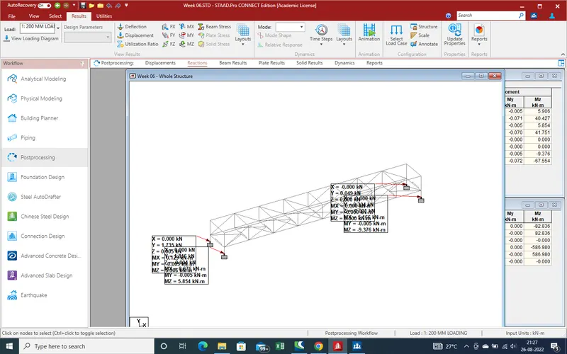
10.Shear force in Z-dirction .
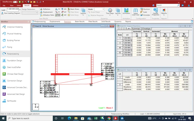
11.Shear force in Y-direction
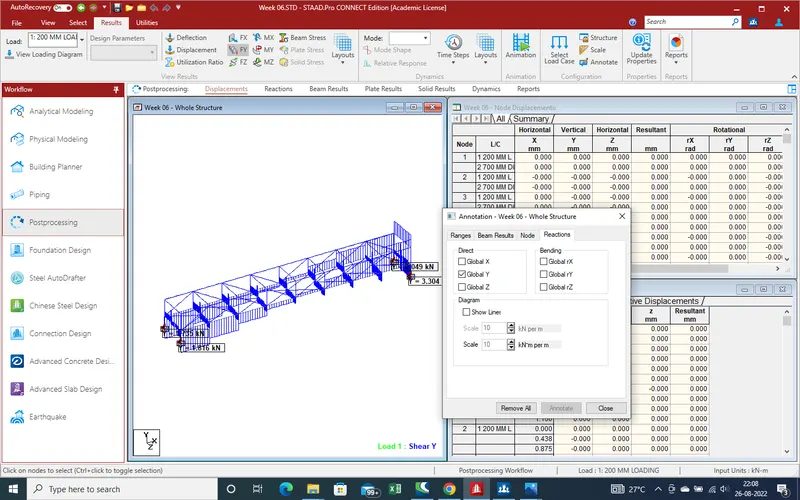
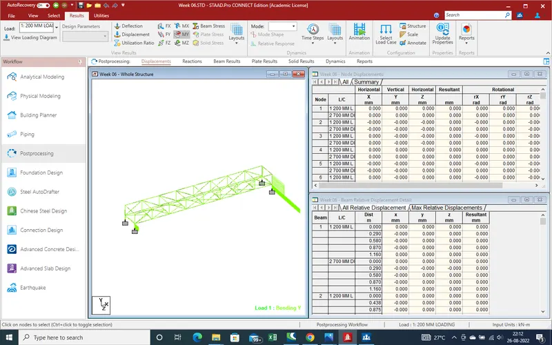
12.Moment reation in Y-direction .
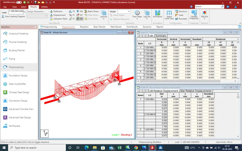
13.Moment reaction in Z-direction
14. Now attached the copy the report and model for find out other results .
thanks