Week 6 Challenge
AIM AND INTRODUCTION:
To calculate the Pipe loads for the bridge shown in figure The width of bridge is 3m. The bridge is located in the banks of river narmada. Two pipes are proposed on the bridge with one being 700 dia NB DI pipe and the other one being 200 dia NB DI pipe. The length of the bridge is 24m. Apply the calculated pipe load in Staad.pro.
GIVEN DATA:
* Width of Bridge=3m.
* Length of Bridge=24m.
* Two pipes 700 dia NB DI Pipe & 200 dia NB DI Pipe.
PROCEDURE:
PIPE 2:
Calculation of Self Weight of DI Pipe:
Since the class of the DI pipe is not mentioned I have assumed as Class K9
For 200mm Dia pipe and class K9 weight =45.28Kg/m.
=0.04528KN/m
For 24m span weight =0.04528*24
=1.08672KN.
Calculation of Live Load of DI Pipe:
The load due to water in pipe=Area*Unit Weight
=π*(0.1)^2*10
=0.314KN/m.
Total load acting on bridge:
=Self Weight of DI Pipe +Live Load of DI Pipe
=0.04528KN/m+0.314KN/m
=0.35928KN/m.
The load is applied on the bridge superstructure as UDL.
PIPE 2:
In the above given problen the DI pipe dia is 700m ,since we have only 600mm DI pipe we will assume that in our problem.
Calculation of Self Weight of DI Pipe:
Since the class of the DI pipe is not mentioned I have assumed as Class K9
For 600mm Dia pipe and class K9 weight =217.19Kg/m.
=0.21719KN/m
For 24m span weight =0.21719*24
=5.21256KN.
Calculation of Live Load of DI Pipe:
The load due to water in pipe=Area*Unit Weight
=π*(0.3)^2*10
=2.826KN/m.
Total load acting on bridge:
=Self Weight of DI Pipe +Live Load of DI Pipe
=0.21719KN/m+2.826KN/m
=3.04319KN/m.
The load is applied on the bridge superstructure as UDL.
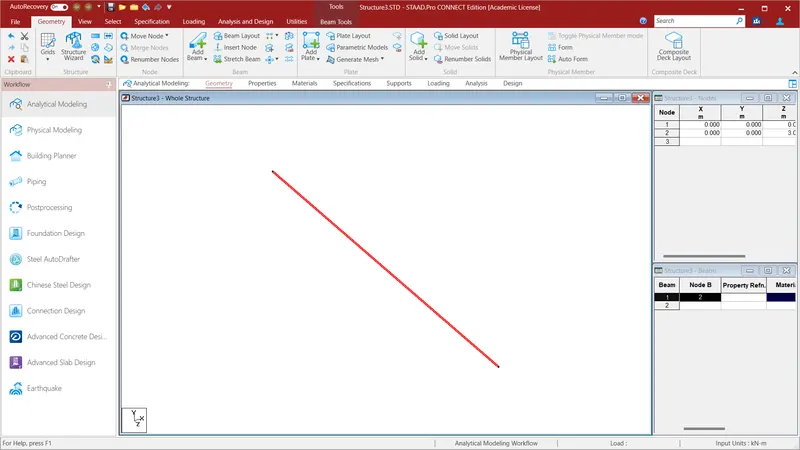
Give the values of Node 1 as X=0;Y=0;Z=0 and Node 2= X=0;Y=0;Z=3m . After that connect the two nodes using Add Beam in Geometry Option. A beam created with a width of 3m.
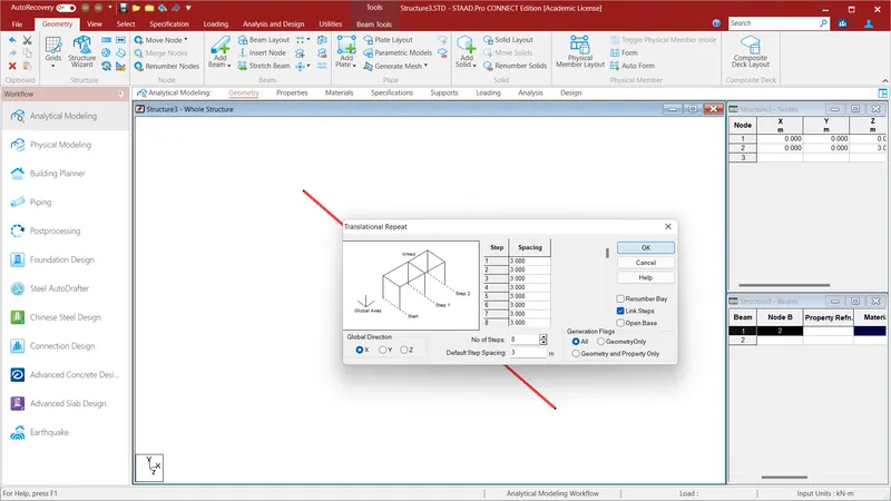
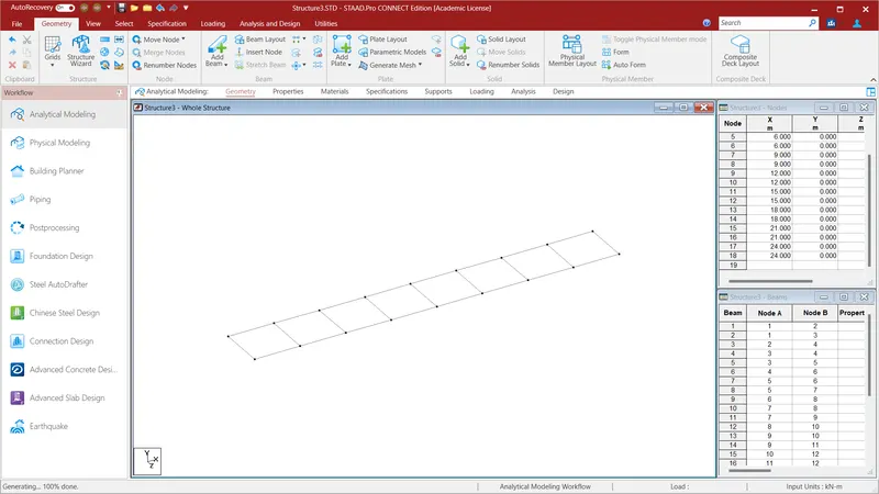
Select the beam and go to Geometry and select the Translational Repeat option and in Global X Direction give the values as No. of Steps=8: Default Step Spacing=3m and Link Steps and click OK. A span of Length 24m with each 3m length and width of Beam 3m will be created.
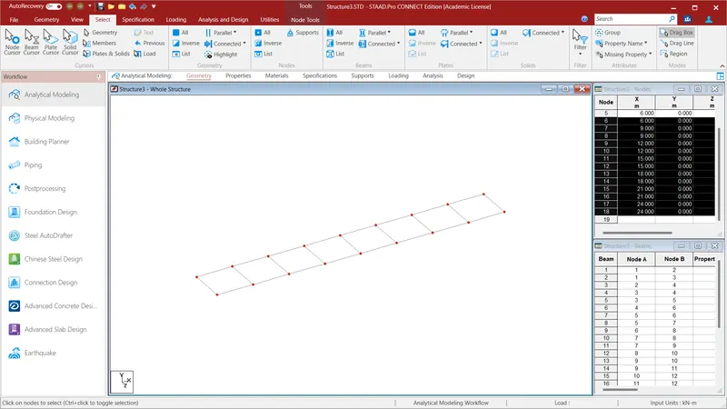
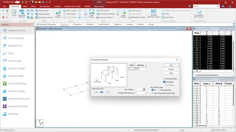
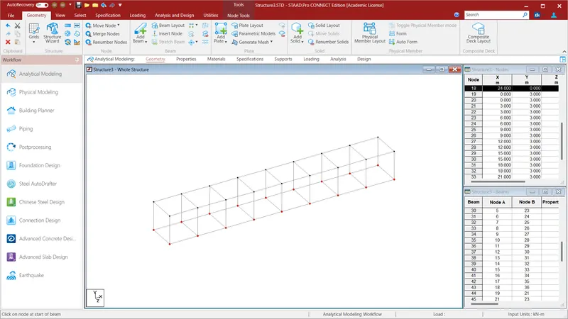
Now select all the nodes using Node cursor in the select option go to Geometry and select the Translational Repeat option and in Global Y Direction give the values as No. of Steps=1: Default Step Spacing=3m and Link Steps and click OK. Now using the Add Beam cursor connect all the nodes so a beams will be created accross the bridge.
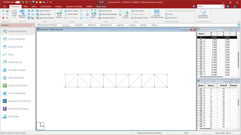
In the given problem the angles members are given in the side view. Do the same for the structure using Add Beam cursor in the Geometry Option.
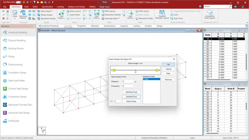
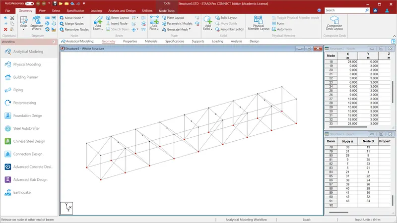
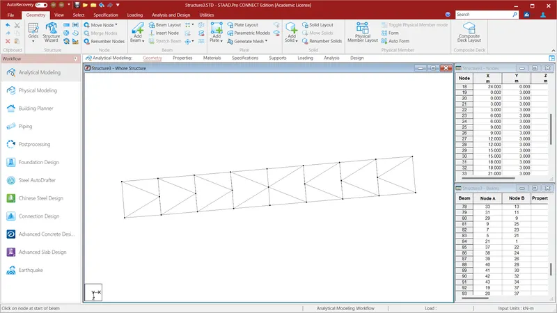
After creacting the angle section we have have create members in the top of the bridge. To do that select the Top Beams and go to the Translational Repeat Option and click the insert Node and select the Add Mid Point option and click ok. Do the same for all the beams. After that as in the given problem connect all the beams and the truss member is created.
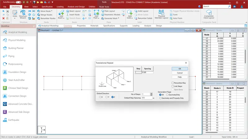
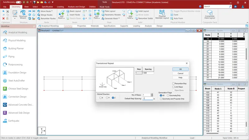
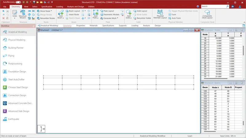
In the above mentioned problem a beam is created at 0.5m from the first beam . To create the beams go to Geometry and select the Translational Repeat option and in Global Z Direction give the values as No. of Steps=1: Default Step Spacing=0.5m and click OK.Join all the beams using Beam cursor in the select option. Now the pipe is to be placed from the other side of the width at 1m . To do so go to Geometry and select the Translational Repeat option and in Global Z Direction give the values as No. of Steps=1: Default Step Spacing=-1m and click OK. A pipe and a beam will be created.
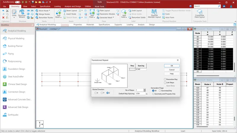
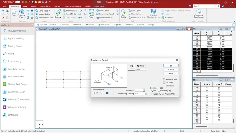
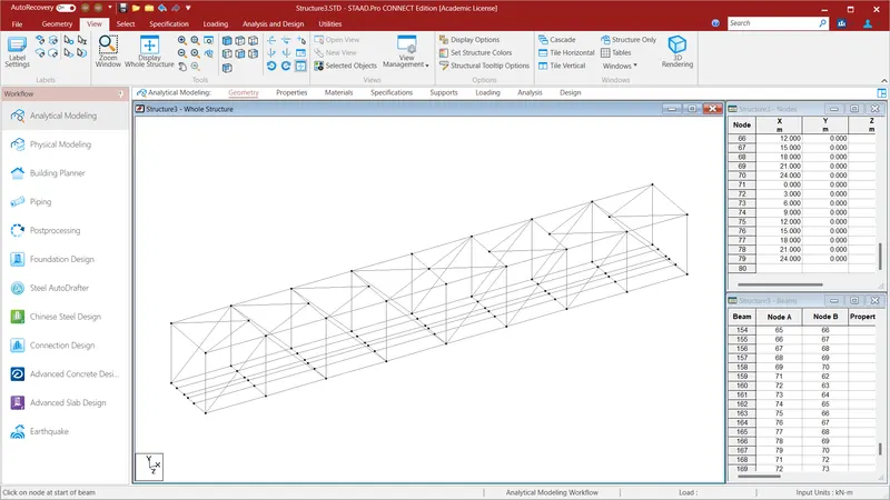
After creating the 600mm Dia NB DI Pipe we have create 200mm Dia NB DI Pipe. To do select the 600mm Dia Pipe using node cursoe select all the Nodes and go to Geometry and select the Translational Repeat option and in Global Z Direction give the values as No. of Steps=1: Default Step Spacing=-0.54m and click OK. After creating the two pipe we have create another member to do that go to Geometry and select the Translational Repeat option and in Global Z Direction give the values as No. of Steps=1: Default Step Spacing=-0.3m and click OK. All the pipes and members are created as mentioned in tha above problem.
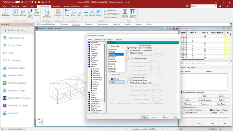
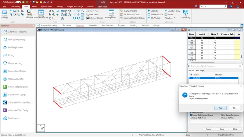
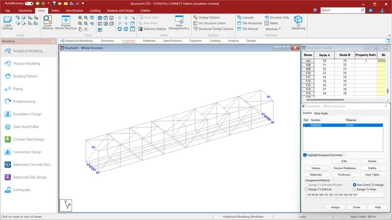
After creating all the members we have assign properties to the given structure To do that go to Specification Option and go to Section Database and select the Indian and select the ISMB 250 in the S Shape. Select the first and the Last Top and Bottom beams accross the width and click Assign to Selected Beams and Assign and click YES. Properties to the corner beams along the width will be assigned.
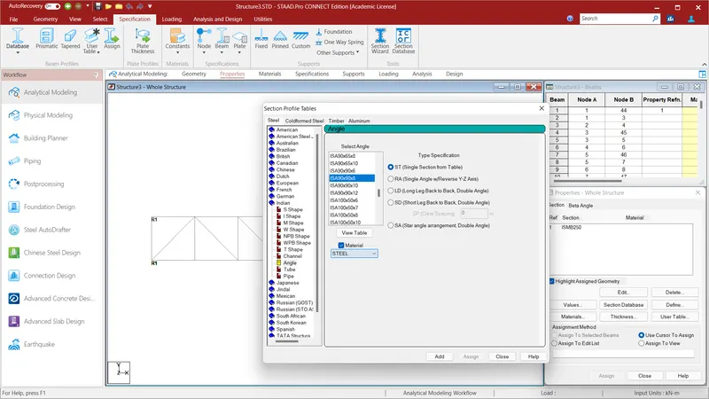
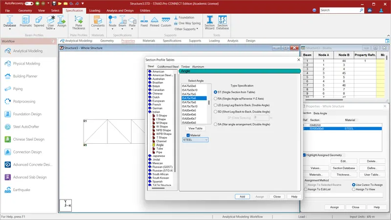
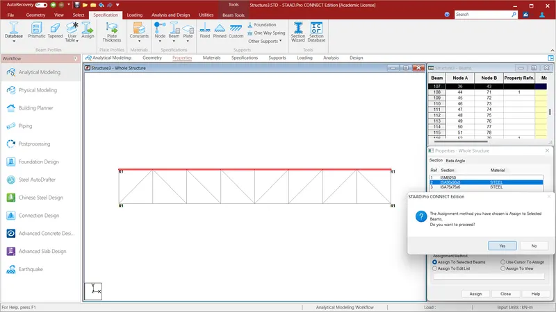
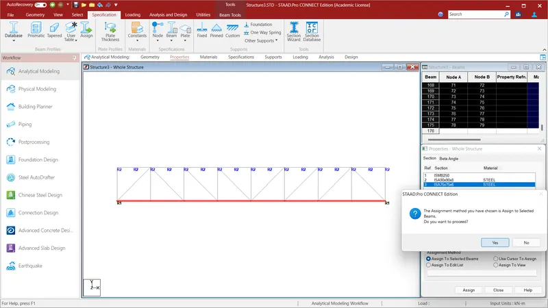
We will assign the properties to the Top and Bottom Beams along the Length of the Span. To do that go to Section Database and select the Indian and select the ISA 90X90X8 in the Angle Section. Select all the Top beams along the Length of the span and click Assign to Selected Beams and Assign and click YES. For the bottom beams along the Length go to Section Database and select the Indian and select the ISA 75X75X6 in the Angle Section. Select all the Bottom beams along the Length of the span and click Assign to Selected Beams and Assign and click YES.
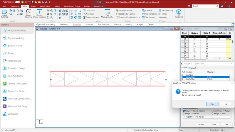
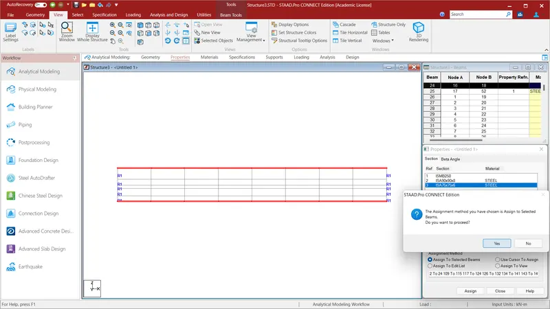
Assign the properties to the selected members of the angle section of ISA 90X90X8 and ISA 75X75X6 and click Assign to Selected Beams and Assign and click YES.
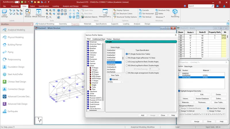
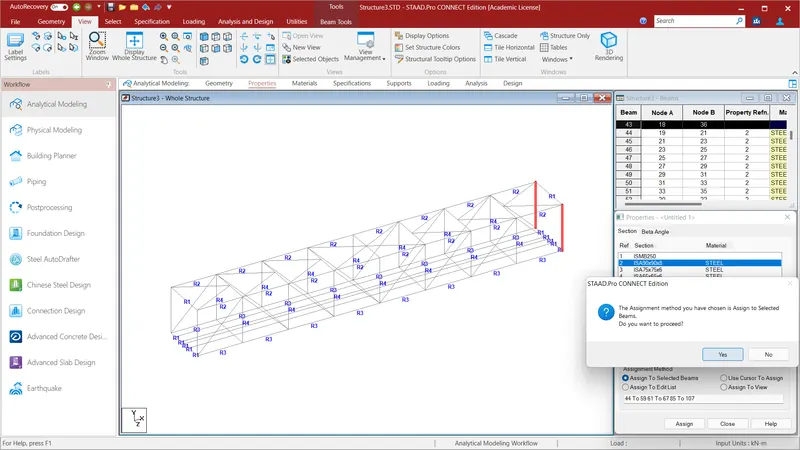
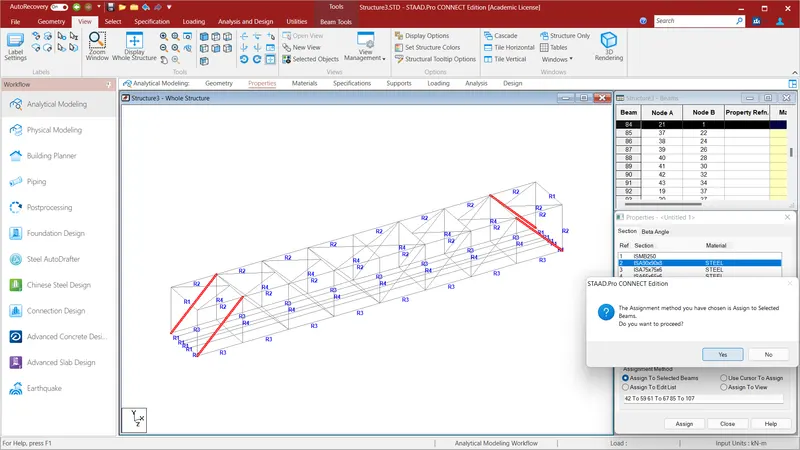
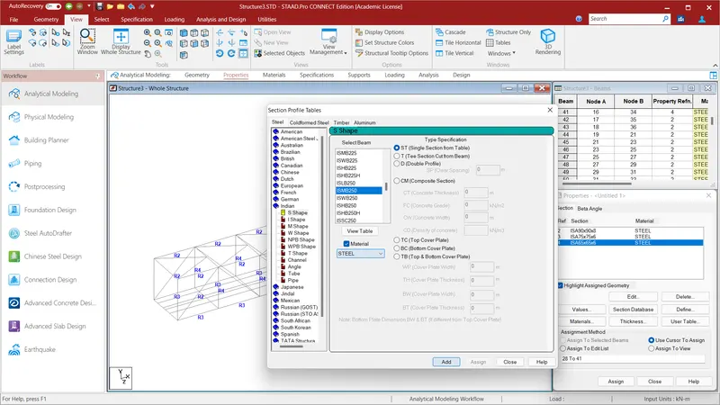
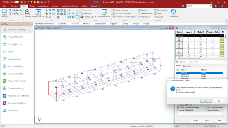
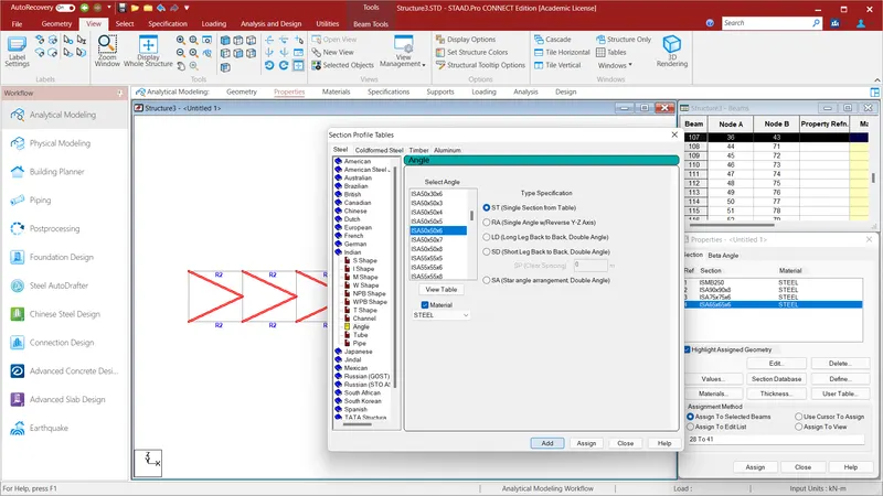
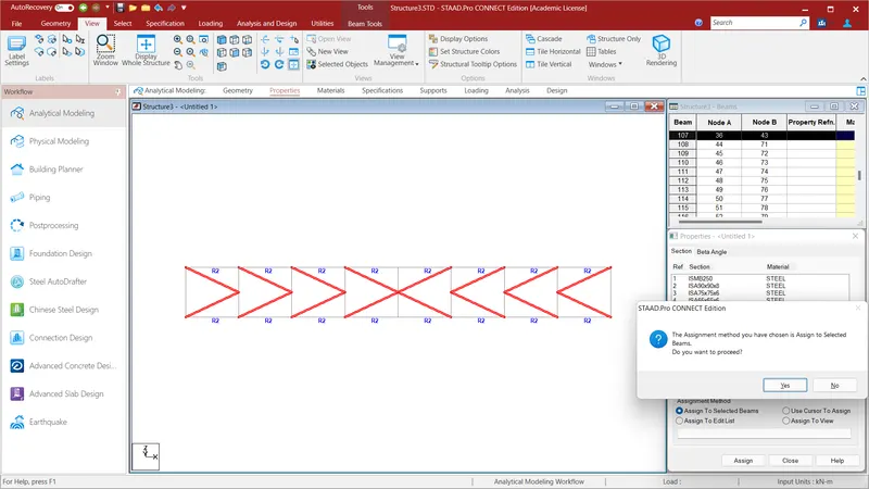
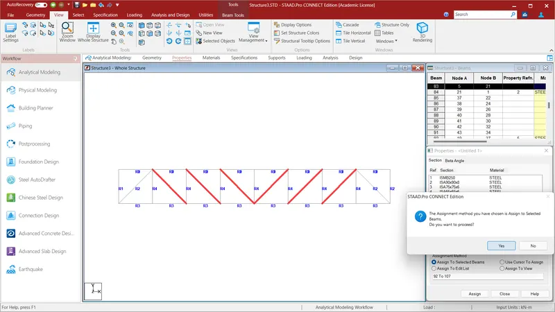
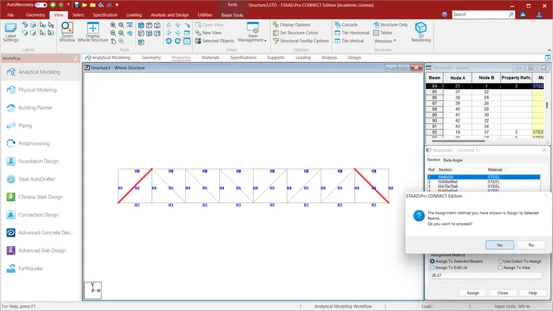
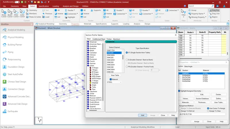
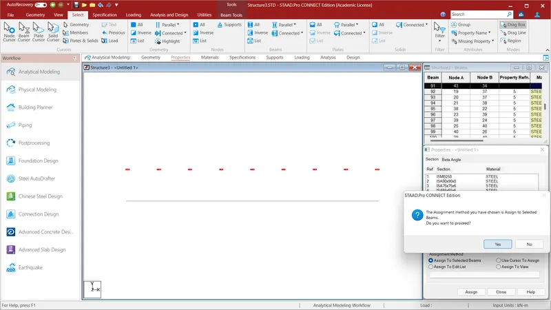
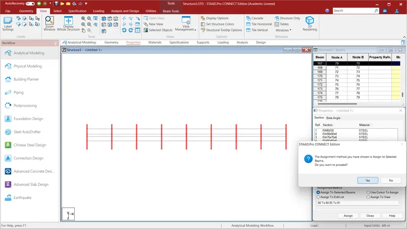
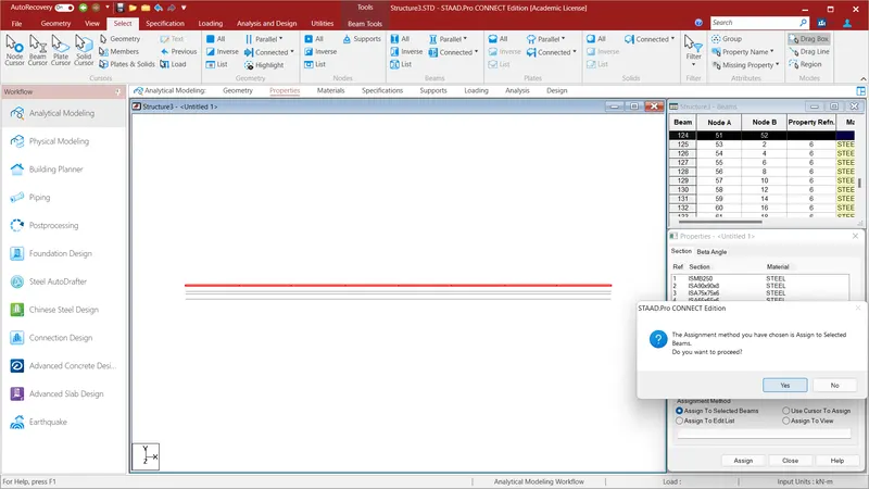
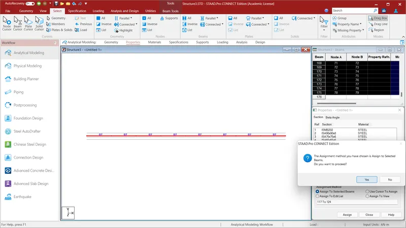
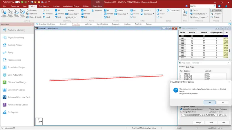
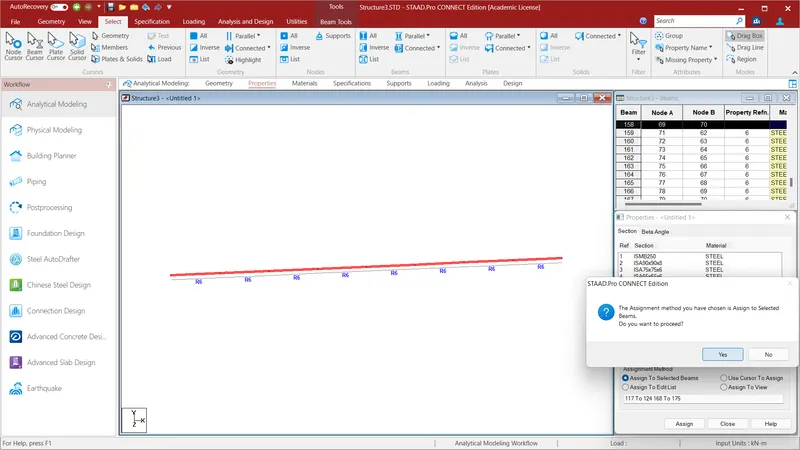
In the above given problem they have mentioned the section members to be provided to the structural members. By seeing that i have assigned the properties to the members as mentioned in the above problems.
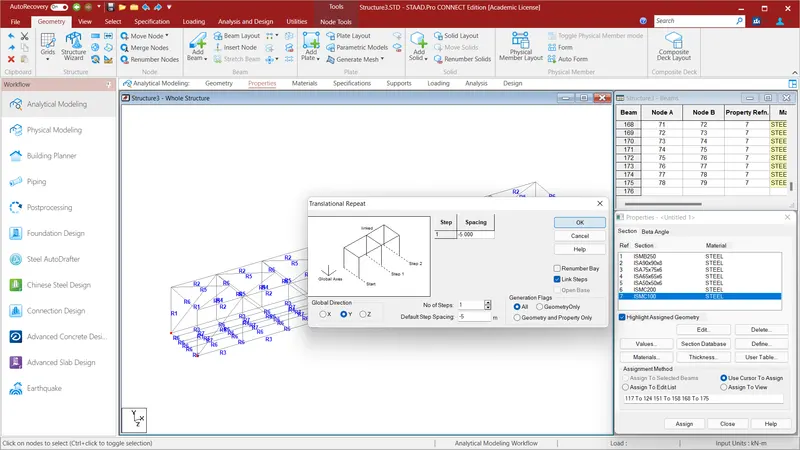
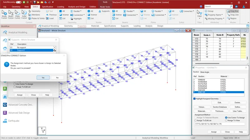
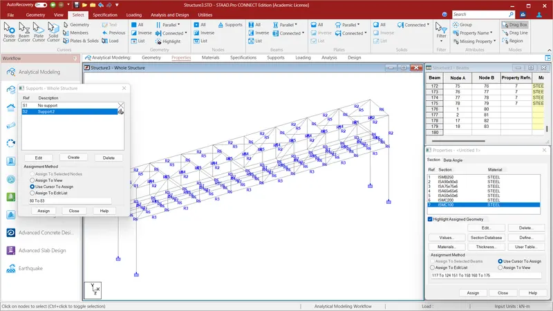
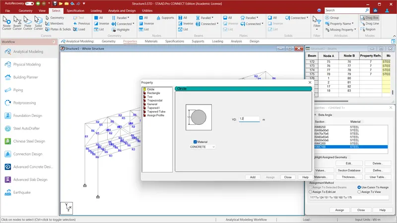
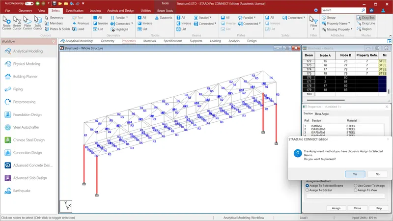
After assigning all the properties to the problem we have create to piers to the bridge. To do so select all the nodes in the corners of the bridge using node cursor in the select option . Now to Geometry and select the Translational Repeat option and in Global Y Direction give the values as No. of Steps=1: Default Step Spacing=-5m and click OK. After create the pier we have assign fixed support to the pier . To do that go to the Specification Option and select Fixed and click ADD and select support 2 option and select all the bottom pier nodes using the node cursor using select option and click Assign to selected Beams and click assign and click YES. We have assign properties to the pier to do so go to the define option in the user table and select circle with a radius of 1.2m and click add and close . Selected all the piers and slecet assign to selected bemas and assign and click YEs. Properties to the piers will be assigned.
RESULT:
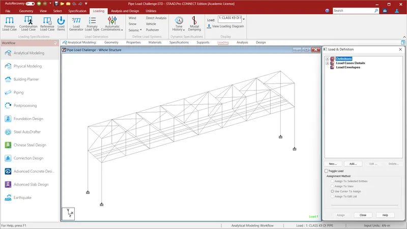
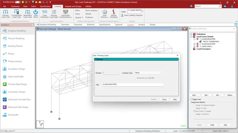
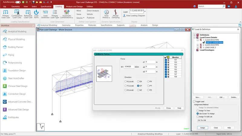
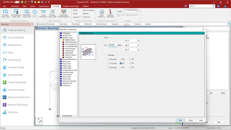
Go to Loading option and select Load Case Details and give the name as CLASS K9 DI PIPE and click Add . Click the CLASS K9 DI PIPE and select the Member Load and select uniform load and give W1=0.04528 KN/m in GY Direction and click ADD and close.
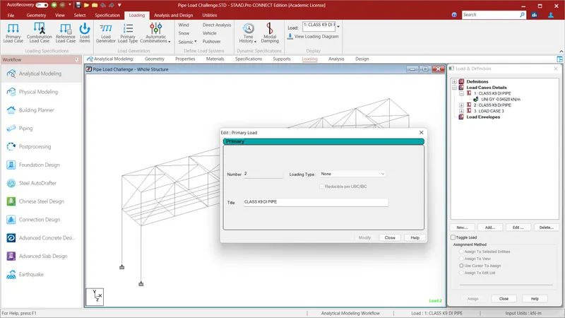
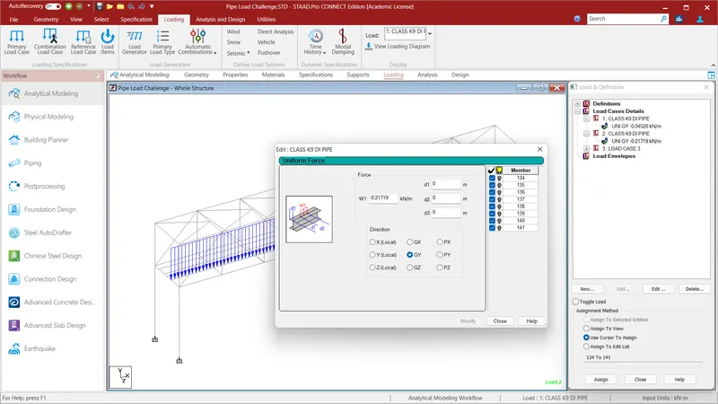
Go to Loading option and select Load Case Details and give the name as CLASS K9 DI PIPE and click Add . Click the CLASS K9 DI PIPE and select the Member Load and select uniform load and give W1=0.21719 KN/m in GY Direction and click ADD and close.
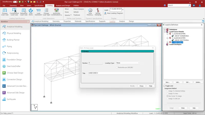
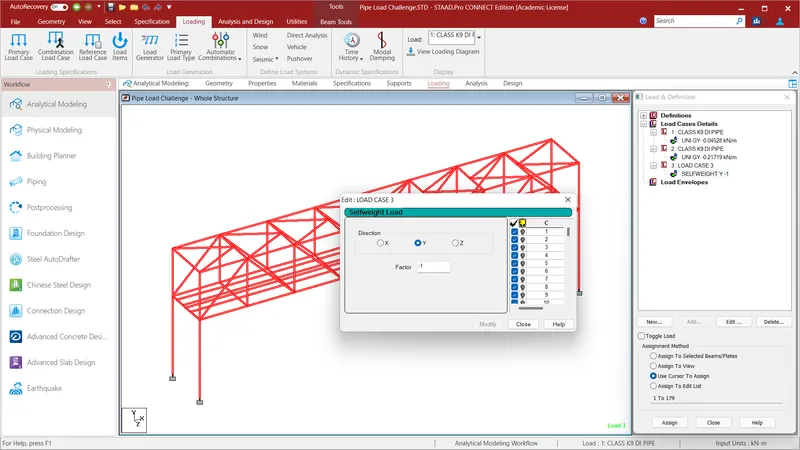
Go to Loading option and select Load Case Details and give the name as LOAD CASE DETAILS and click Add . Click the Self Weight and select the Member Load and select uniform load and give Factor=-1 in Y Direction and click ADD and close.
REPORT:
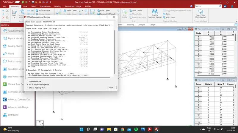
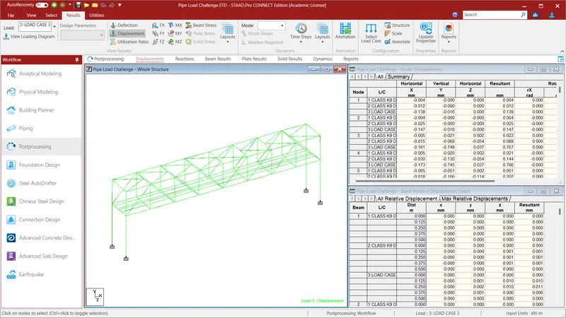
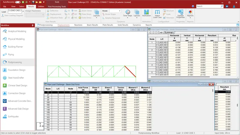
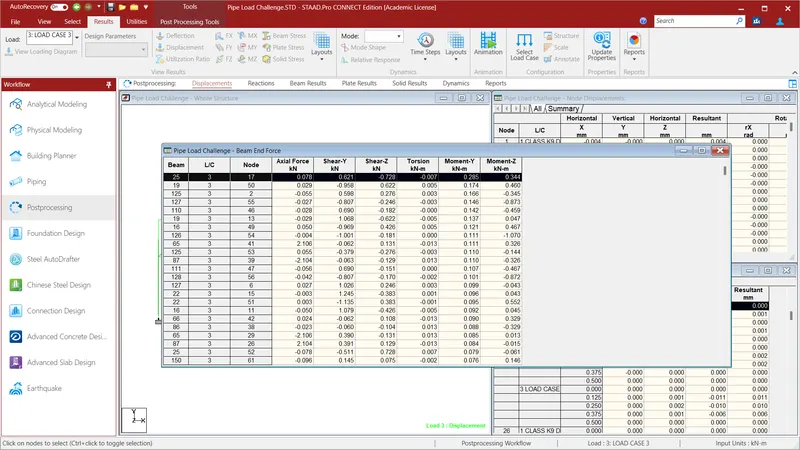
Maximum Moment at X and Z
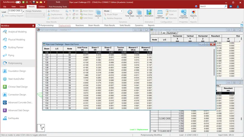
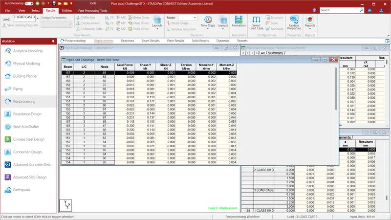
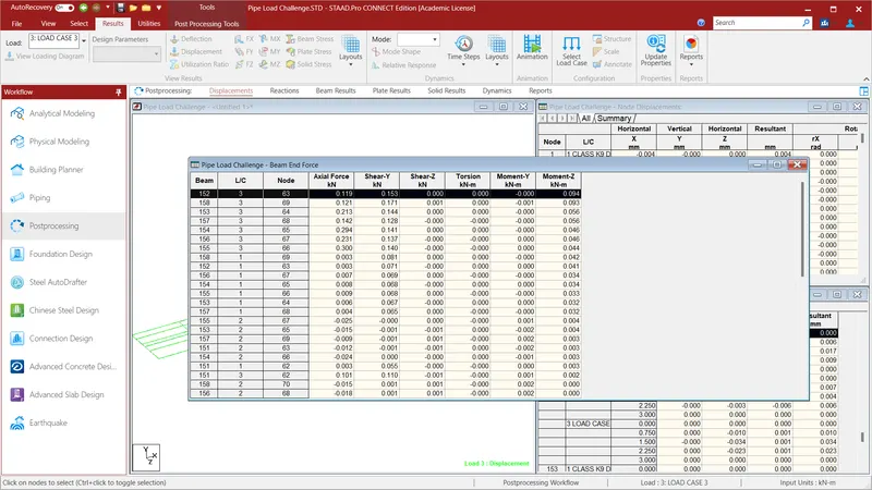
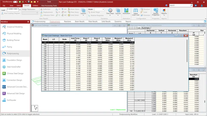
Moment acting on the DI pies in X and Y direction.
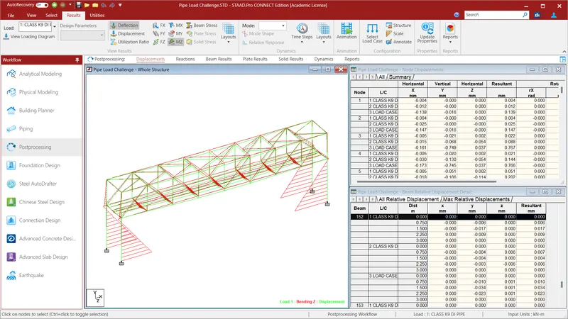
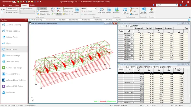
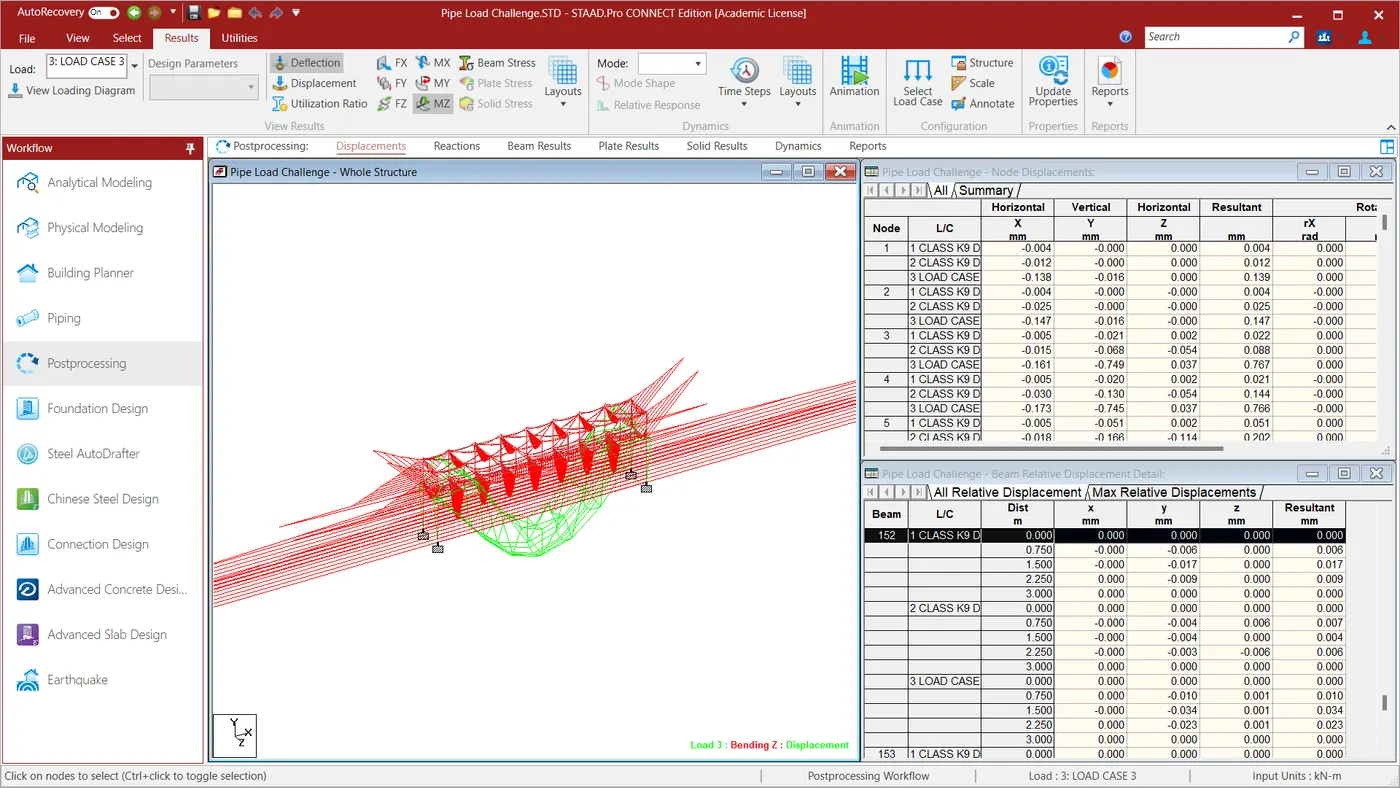
Moment acting on Z in 200mm DI Pipe and moment acting on Z in 600mm DI Pipe and self weight of the bridge is applied.
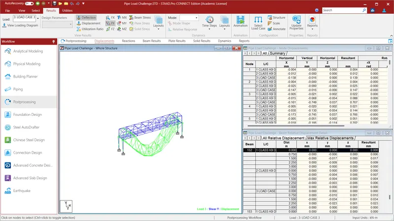
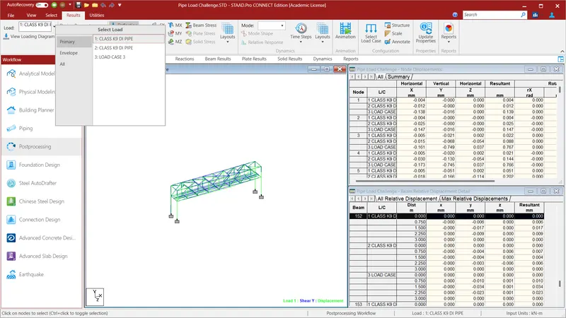
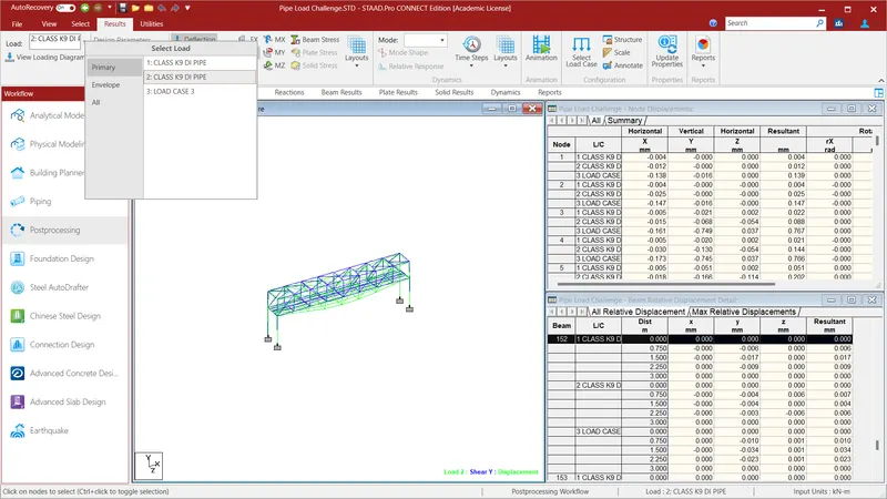
Deflection acting on 200mm and 600mm Di Pipe in Y direction and self weight due to deflection in Y direction is applies.
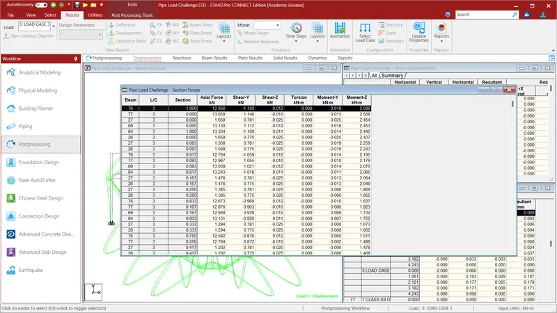
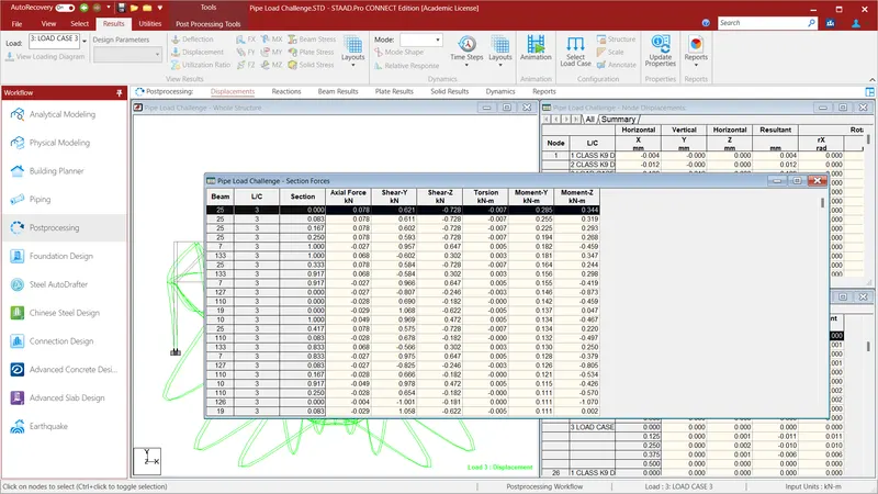
Section forces acting at moment at Z and Y .
For the given Problem we have calculated
* Beam End Forces
* Section Forces.
* Moment at Z and Defelection at Y for the pipes and self weight.