Week 6 Challenge
Q1. Microstation rectangle to complex line with matchline FD
Aim& Introduction
The aim of the assignment is to convert a microstation line into a complex line with Civil Rules and ORD has the functions to do this conversions in most simple way which will be discussed below.
Procedure
The step by step procedure for creating complex line from microsation line is given below.
Open ORD=> Create a new file with 2D seed file=> load the file=> Go to Drawings tab=>click place a line
Draw a rectangle with the line command=> go to properties to see the microstation line properties
Go to Geometry=>Design Elements=>Create civil rules=>window appears=>No FD
Now select each line in the rectangle=> all the lines converted to dotted lines=>click on any line=>civil handles can be seen in the line
Now Go to Complex Geometry=>Select complex by element=> window appears=>select each line and accept it=> Go to element selection=> click on any line=>see that all rectangle is selected with complex element features
Now go Standards=>set FD=> Linear=>Miscellaneous=>Match line=> Now FD has been assigned
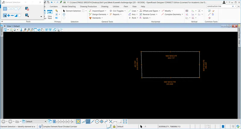
Results
Thus, the microstation lines can be converted into complex elements with specific Features Definition.
Q2. Geometry builder tool (Not covered in week 6 videos)
Q3. Alignment design for first intersecting Street and Proposed profile
Aim and Introduction
The aim of the alignment design to create a horizontal alignment with ORD geometric design tools and to standardize it with various tools available in the ORD.
Procedure.
The procedure for creating the alignment and profile is explained below.
Open ORD => New file=>Seed 2D and Name file as Int_01
File loads up=>go to attach file by reference attachment=> survey topo.dgn file=>attach the file with surface to grid factor 1:1.00012=> file loads up=>go to Utilities and setup the coordinate system=> now turn off all levels except the existing pavement edges and C/L by the Level display.
Go back to the reference attachment method and attach the existing and proposed ROW files.
Again go back to the level display and select each model and hide unnecessary data except the existing and proposed edge lines ( Please check the line properties before going into Level display)
Go to attributes and click level override to view the lines in white and orange colour.
Now click the space key in the keyboard and microsation menu pops up=> now click copy=>select the 1st straight portion (or simple element) near the junction (just after the radius part) move from the base snap point and return and keep it in the same point in order to keep it active.
Now turn off the proposed ROW from the Level display which is very important
Go to complex tools=>click Define by best fit=>window appears=> Best fit=>Complex by edges=>Envelope parameter=>0=>Rounding parameter=>0=>Include spirals=>no=>Default Radius=>3000
Select primary and secondary objects and accept it a new proposed C/L appears in white colour
Now click the C/L and flyout menu appears with and additional option convert to horizontal rules=>click the C/L and accept it
Now turn on the Aerial Image, also turn on the Proposed ROW lines and now go along the line and select any portion with a narrow ROW and repeat the same procedure (Before that Go to Horizontal lines=>window appears =>assign FD=>alignment =>preliminary planning=> Geom tmp.( Do make the temp C/L a complex line before drawing arcs).
Now after creating the new C/L delete both parent lines and repeat the procedure near the end of the road with intersection point. And go to arcs => Arc between elements => Draw new arc matching the alignment C/L.
Now turn on the aerial image and extend both lines till the intersection and check the angle difference between tangents, if its more than 1 degree provide curve to make it smooth. Also after this we want convert the lines into a complex line by complex by element method.
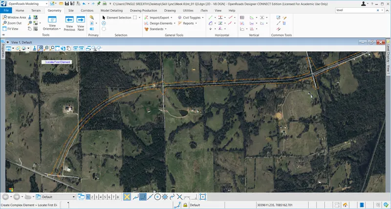
Procedure to add Station to a line
Go to Drawing=>Modify=>start station=>locate the element=> assign start distance=>go to the start point=>enter the station value 50+00 now the station value has been assigned.
Now turn on Civil toggles=>click station offset=>click on any point on the line it shows the station as zero=> Now go to Civil toggles=>hold on the drop-down menu=>E switch dialogue mode=>new window appears=>pick the C/L line and chainage can be seen as per the cursor movement on the line.
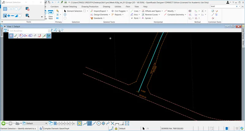
Results
Thus, a station can be assigned to the Road C/L.
Q4. Design a roadway layout for intersecting streets.
Aim & Introduction.
The aim of this section is to describe the design methodology for roadway layout and the procedure will be discussed below.
Procedure
The step by step process for creating the roadway layout with intersecting streets is being discussed below.
Open ORD=>create a new file with 2Dseed file=>Name it Roadway plan=>Go to geometry=>Attach reference file=>attach the previous file which used to create roadway alignment.
Note: all the previously attached references can be seen in the reference attach window.
Now turn display off the Topo.dgn and topo existing and => single offset entire element =>window appears=>assign FD =>Road Pavement Edge and apply select c/l => offset 12 and mirror it.
Again go to single offset entire element =>apply FD=>shoulder=>Road shoulder=> assign offset 10' and do it for both road edge lines separately.
Go to reference display and turn on the topo.dgn file and go again to reference display menu and right click on the roadway plan.dgn => click activate=> everting will be in grey colour other than C/L and click and drag the C/L civil handlels to extend it up the junction C/L.
Go back to reference attach window and right click or click on the black dot to deactivate it.
Go to lines and draw a c/L for the junction road with FD -temp geom and go to offsets and tapers=>single object entire element with FD road pavement edge and draw offsets at both sides => turn of topo.dgn
Now go to arcs =>arc between elements=>simple arc=> pick pavement edge lines for both roads and draw an arc at R 60 and do it for the other side too. Apply trim both option while doing this process and assign FD for curve later.
Note: while trimming one line may disappear but it will appear back while doing the opposite side.
Move to 2nd intersection and do the same process. Also do the same process for intersection 3 and now it is to be noted that existing intersecting roads and extending beyond the limit of work and appropriate tapering to be provided till the limit of work. Now turn of the snap tool and go to offsets and tapers=>select ratio offset=>select appropriate FD => Draw ratio line till the limit of work and do this process for all intersecting streets.
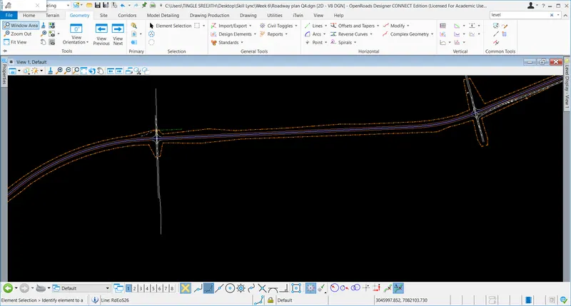
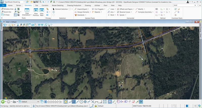
Results
Thus, roadway layout design on intersecting streets can be done.