Week 6 Challenge
1.ANS.
Summarize study for the bending moment, shear force, and deflection diagrams for the elements of the model.
Bending Moment: A Bending Moment (BM) is a measure of the bending effect that can occur when an external force (or moment) is applied to a structural element. This concept is important in structural engineering as it is can be used to calculate where, and how much bending may occur when forces are applied. The most common structural element that is subject to bending moments is the beam, which may bend when loaded at any point along its length. Failure can occur due to bending when the tensile stress exerted by a force is equivalent to or greater than the ultimate strength (or yield stress) of the element. If a beam is not well-restrained, a bending force may cause it to rotate about a pivot point.
To calculate the bending moment, the magnitude of the force is multiplied by the distance of the force from the point of support.
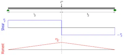
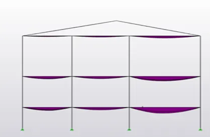
Shear Force: A force acting in a direction parallel to a surface or to a planar cross-section of a body, as for example the pressure of air along the front of an airplane wing. Shear forces often result in shear strain. Resistance to such forces in a fluid is linked to its viscosity. Also called shearing force.
Shear force at any section is basically the algebraic sum of forces acting on either side of the section.
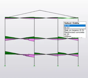
It is important to calculate both BM and SF because it is extremely handy when it comes to structural design. By determining the values of SF and BM across the structure then we can accordingly decide the material or size of the member to withstand the internal forces and moments. It is very important if we use the wrong material or size may lead to the failure in the structure to bear the designed loads.
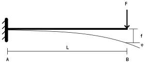
Deflection Diagram: Deflection is the degree to which a structural element is displaced under a load (due to its deformation). It may refer to an angle or a distance. The deflection distance of a member under a load can be calculated by integrating the function that mathematically describes the slope of the deflected shape of the member under that load.
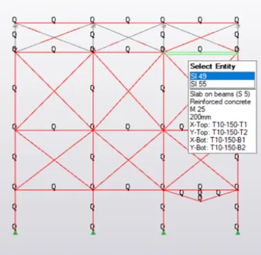
- ANS.
AIM: To analyze the design of the members and outline the thought process in selecting the member sizes along with the foundation design.
Procedure:
Step1: First open the previous model and now, under the load tab, we have to generate seismic load that will redirect to a new window.
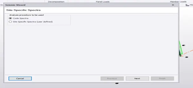
Step2: Give the details of the structure in the appeared Dialogue boxes.
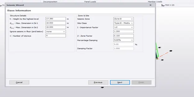
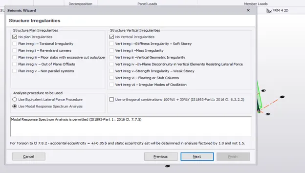
As it is an RC steel building select it as RC- Steel composite building.
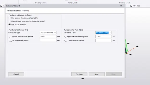
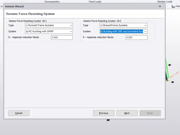
Now select all the load cases for seismic analysis.
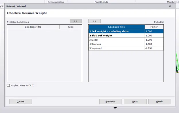
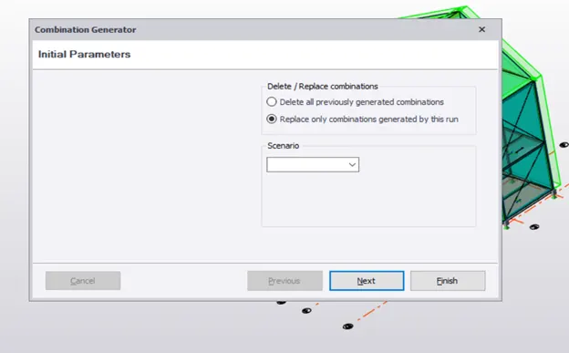
Finally, click on finish.
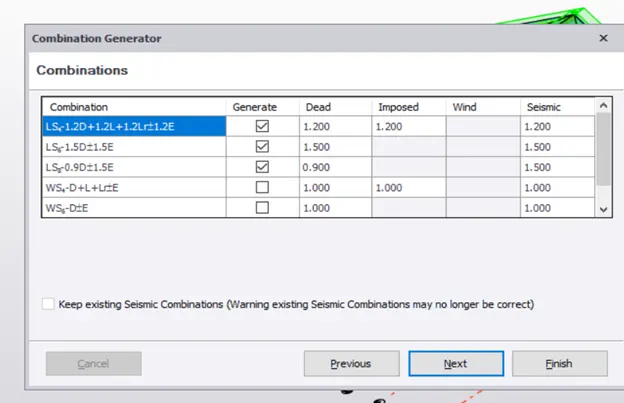
Step3: After the application of seismic loads now finally the seismic load will appear in the loading list which is at bottom of the window.
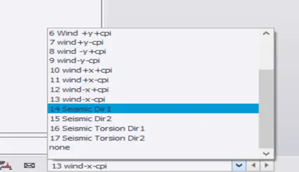
After that, we have to validate the model to check the errors in the model. If any we have to rectify them and proceed with the analysis
Step4: Now in the analysis tab check the analysis settings if any changes we have to do them before the analysis only.
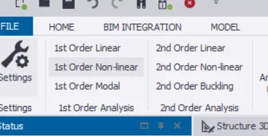
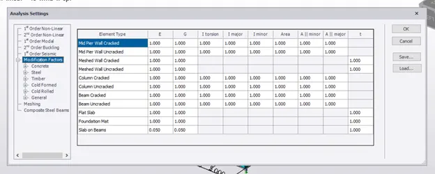
Step5: After settings, we have to do an analysis that is a first-order linear analysis.
Select all the load combinations and cases and click on ok then the model is analyzed.
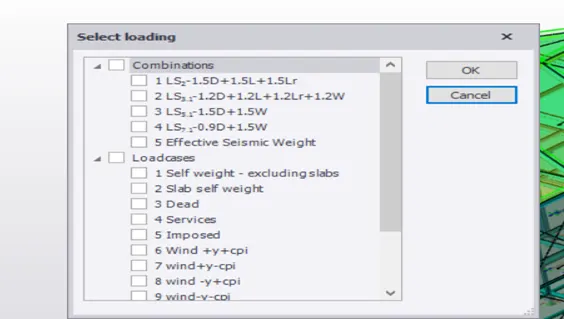
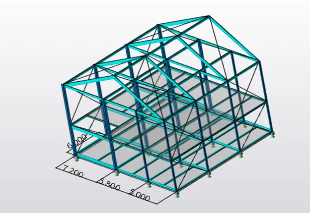
After analysis, if any errors are there they will appear with a solid arrow. We have to rectify them according to the error.
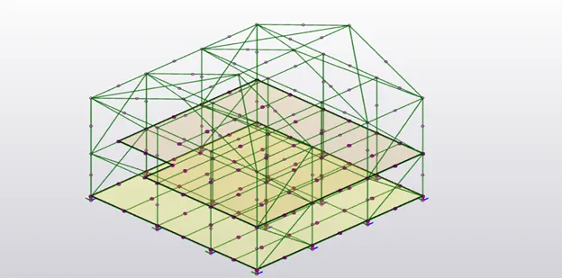
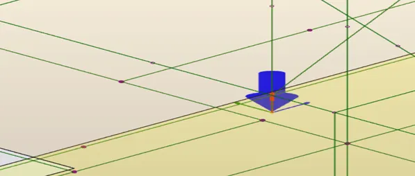
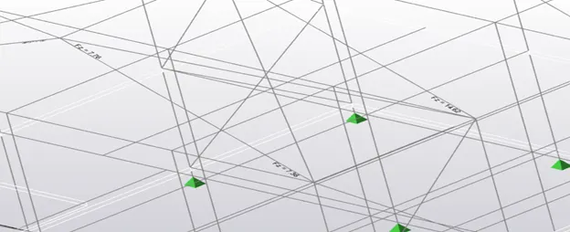
Step6: After analysis, we have to check the results in the results view. We can check axial forces, shear force, bending moment, reactions, Deflection, etc., as shown below.
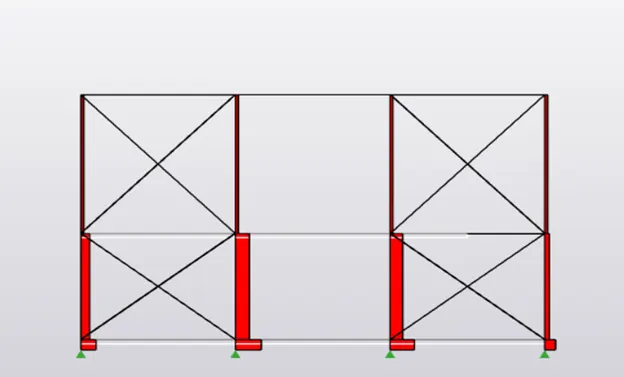
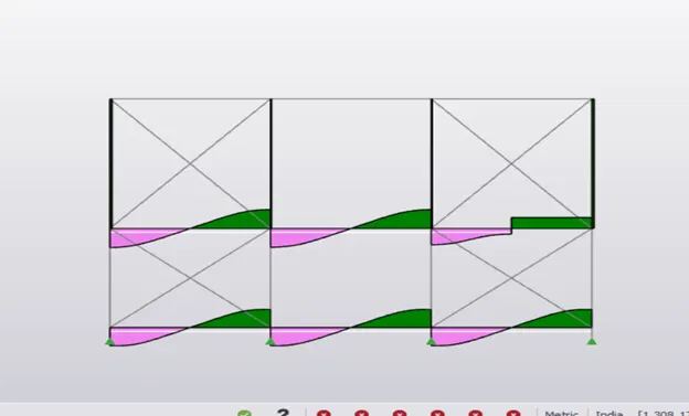
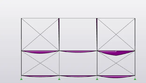
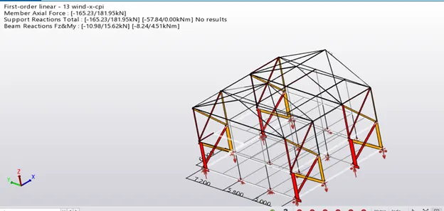
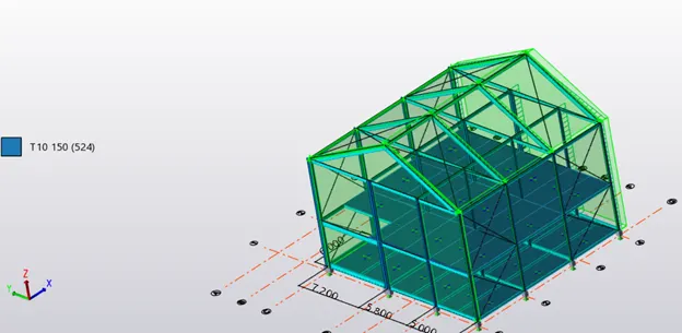
Step7: We can also check the reinforcement in the design tab.
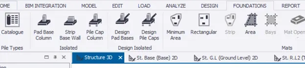
Step8: Now we have to do the foundation. So go to the foundation tab and click on pad base then select the support of the pedestals in the base level to assign the pad base.
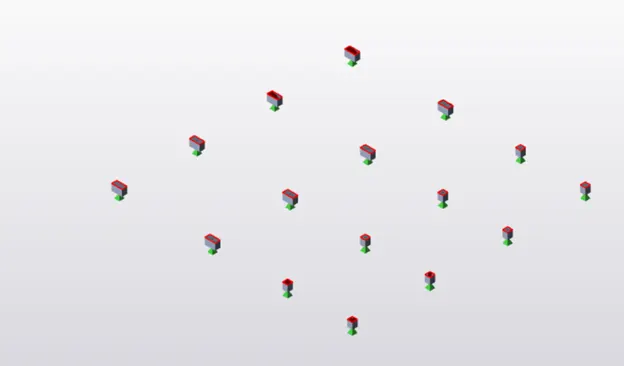
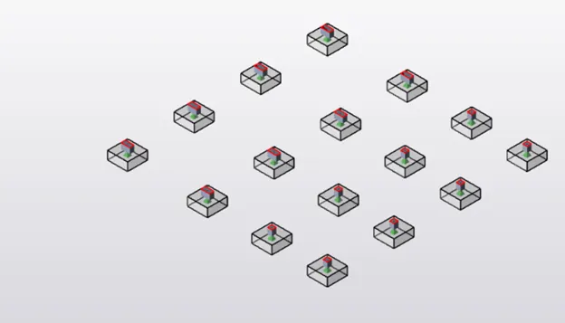
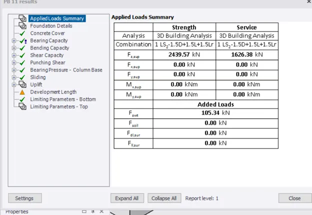
Step9: After assigning the pad base then right-click on the base and various options will appear then select the design member then Tekla will automatically design the member. Then results of the pad base will appear like below.
RESULT: Hence by following the above steps we will analyse and design the members of a structure.