Week 6 Challenge
- Summarize your study for the bending moment, shear force and deflection diagrams for the elements of the model.
ans)
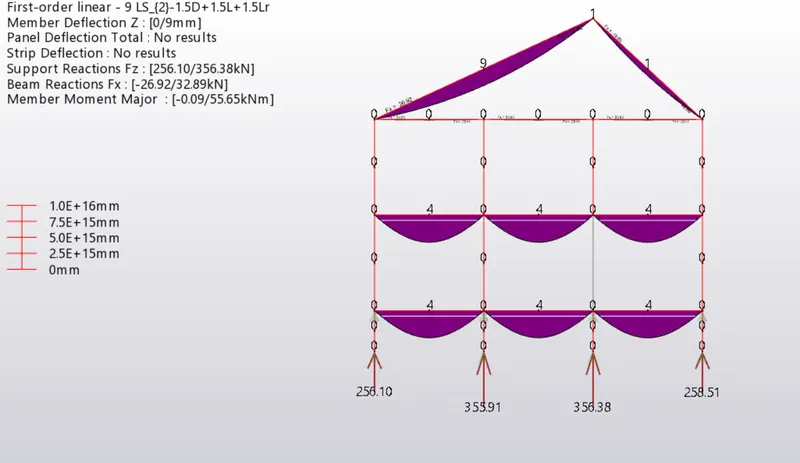
BENDING MOMENT:
It refers to the bending or twisting of member due to the applied forces.
In the figure below we can see simply supported beams subjected to certain udl and the
bending moment values are shown.
since all the supports are hinged,therefore reaction at ends is zero.
concave shape at the centre represents the bending of beam due to load applied.
SHEAR FORCE:
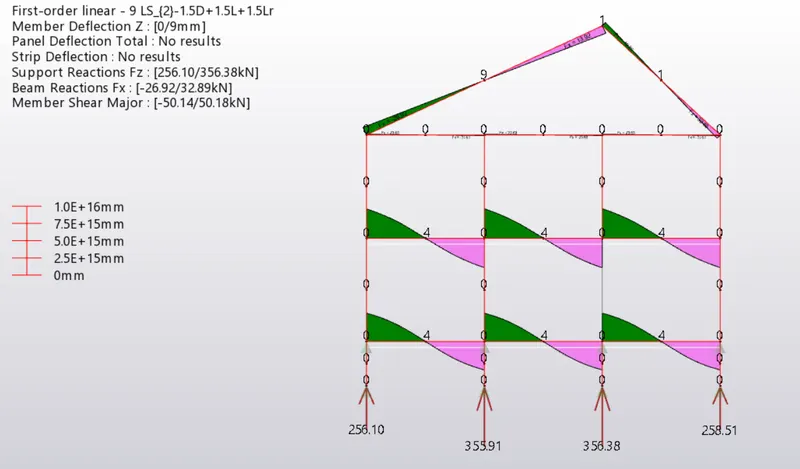
It is defined as system two equal and opposite forces acting side by side or at close distance.
usually it occurs at the supports of a beam,where there will be upward force applied at ends and
reaction will be developed at the bottom,hence creating a system of two equal and opposite forces.
as per the above explanation we can see that in the below figure, reaction is maximum at ends and
zero at centre.
DEFLECTION DIAGRAMS :
deflection refers to the settling or deforming of structural members such as beam ,columns.
these components move from their place to some extent due to the applied forces.
allowable deflection is span/250, if it exceeds then dimensions of the members should be changed.
in the figure below all the members have deflection in limit.
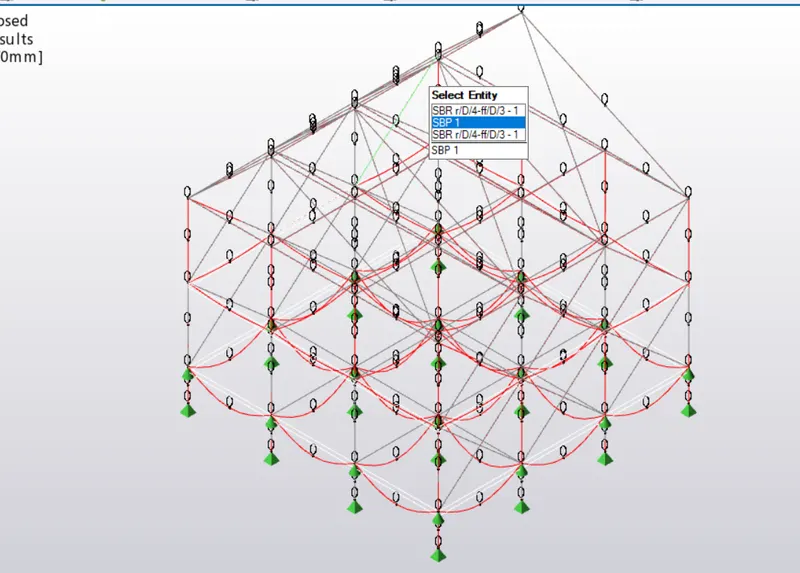
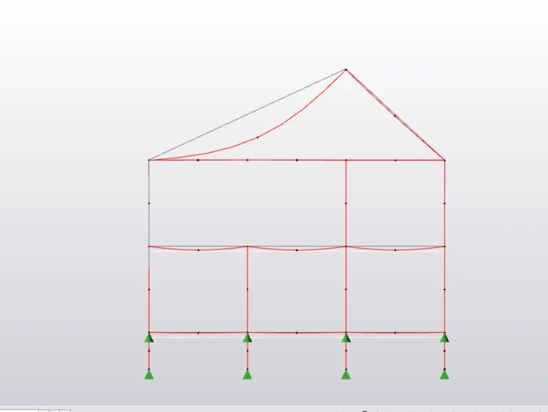
- Based on the analysis design the members and outline the thought process in selecting the member sizes along with the foundation design.
ans)
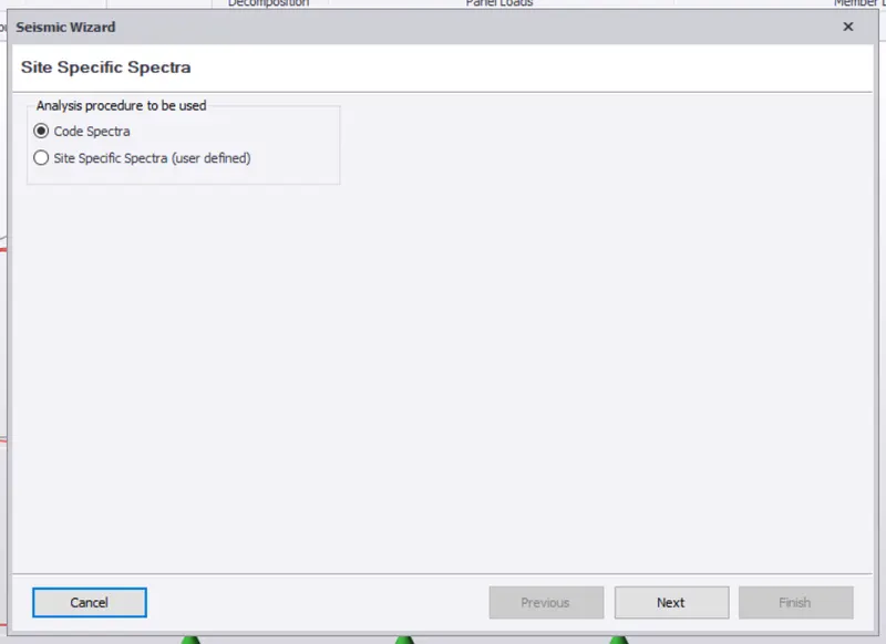
to start with analysis, go to seisimic wizard from the ribbon and select the code spectra,click next.
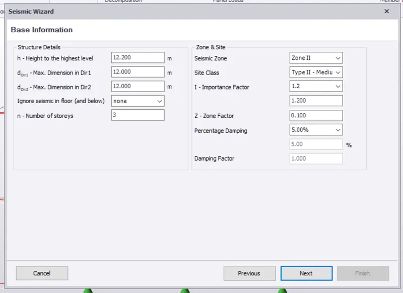
in the next table all the values will be taken by software as shown except zone and importance factor.
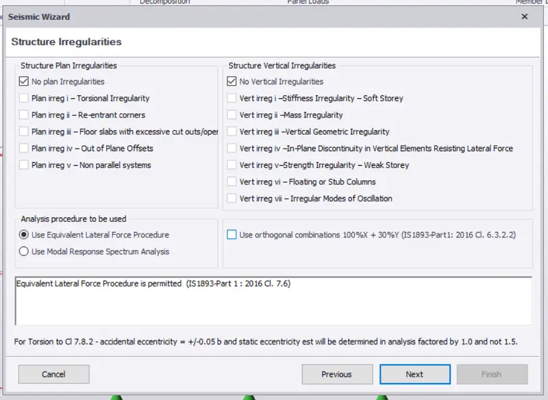
next window, select no plan irregularities in both the columns, click next.
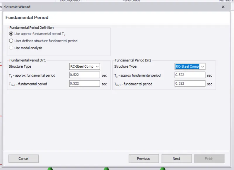
enter the structure type as steel composite structure, click next.
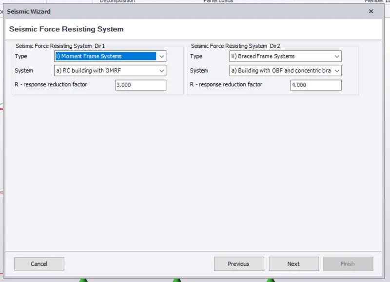
select the moment frame as OMRF and enter the response reduction factor, click next.
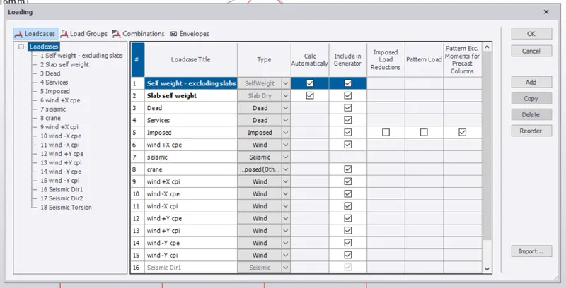
now go to the load cases and enter the following cases, click ok and go to load combinatons click generate.
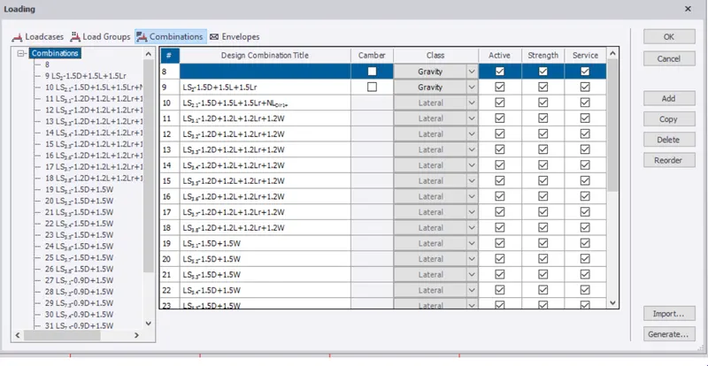
now go to analyze tab and select 1st order analysis after setting the modification factor as 1.
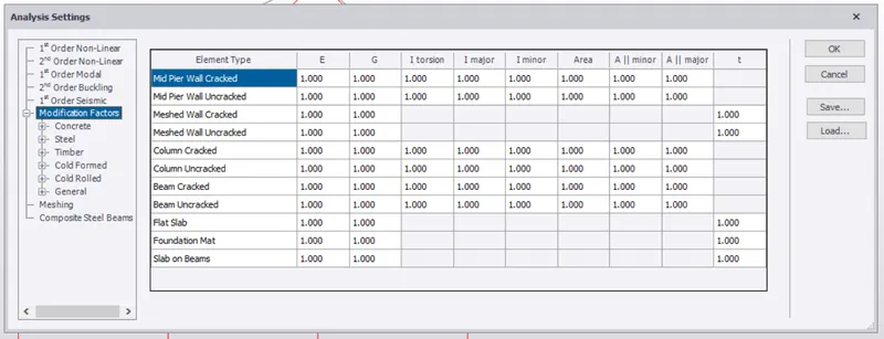
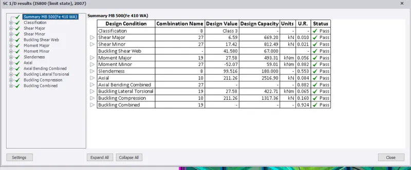
analysis is complete ,now start checking the members for design, select any one member ,right click on it
and then select check member a list will be obtained as shown below.
here member is passing in all conditions,if it fails just click on the criteria and correct it by increasing the size.
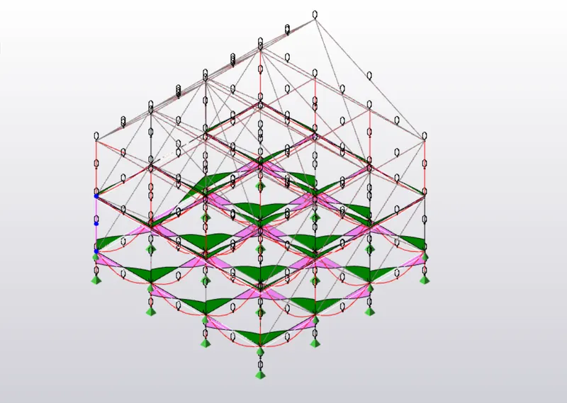
repeat this procedure for all the members, design is complete and display the shear force and bending moment diagrams.
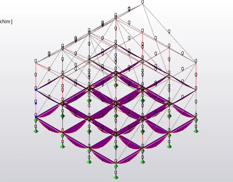
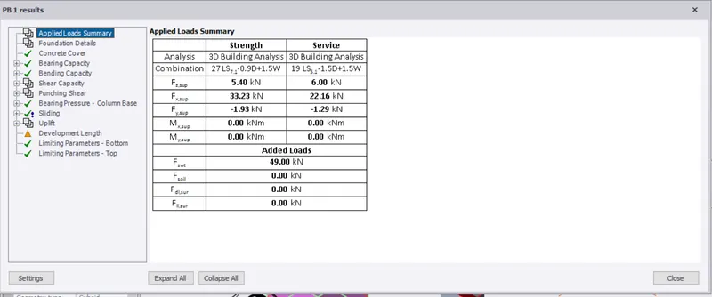
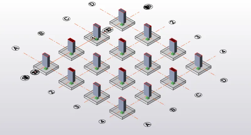
now , to design foundation, go to foundation tab from ribbon and select pad base, assign it to any one column
with some assumed dimension and check it for design.
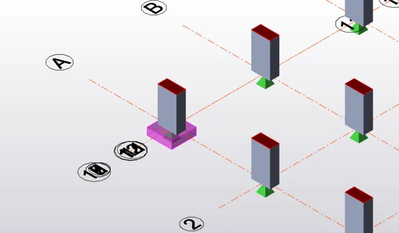
as we can see here it is suitable for all the conditions ,assign the same to all the columns.