Week 6 Challenge
1. Summarize your study for the bending moment, shear force and deflection diagrams for the elements of the model
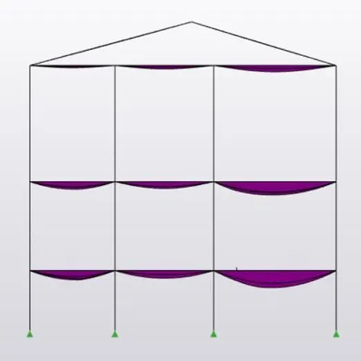
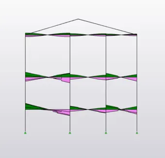
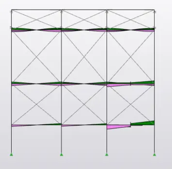
Bending Moment : Bending moment (BM) is a measure of the bending effect that can occur when an external force (or moment) is applied to a structural element. This concept is important in structural engineering as it is can be used to calculate where, and how much bending may occur when forces are applied. It is one of the important topic in analysis part. In tekla we have an advantage to find bending moments, which further strengthens the structure. It can be calculated as the algebraic sum of moments w.r.t. the section of all the forces acting on either side of the section.
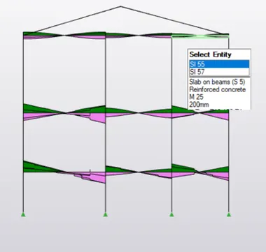
Shear Force : A shear force is a force applied perpendicular to a surface, in opposition to an offset force acting in the opposite direction. This results in a shear strain. In simple terms, one part of the surface is pushed in one direction, while another part of the surface is pushed in the opposite direction. Shear force refers to the force which is acting along the surface, the shear force at any section is basically the algebric sum of the lateral forces acting on either side of the section. Shear force also play a major role in analysis of the structure.
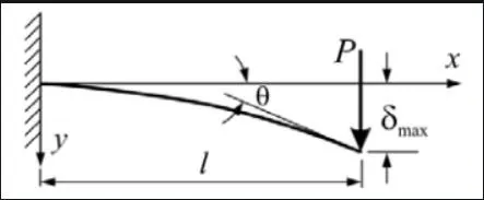
Deflection Diagrams : The deflection distance of a member under a load can be calculated by integrating the function that mathematically describes the slope of the deflected shape of the member under that load. The deflection distance of a member under a load can be calculated by integrating the function that mathematically describes the slope of the deflected shape of the member under that load. The degree of deflection increases with the distances between the supports or the amount of load applied on the member. Deflection diagrams shows the load acting on the member.
2. Based on the analysis design the members and outline the thought process in selecting the member sizes along with the foundation design
AIM : To analyse the design members and outline the thought process in selecting the member sizes along with the foundation design
TOOLS REQUIRE : Validate, loads, load cases, project browser, property window, foundations, 1st order linear etc.
PROCEDURE :
- Firstly open the previous project file
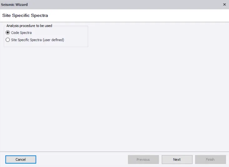
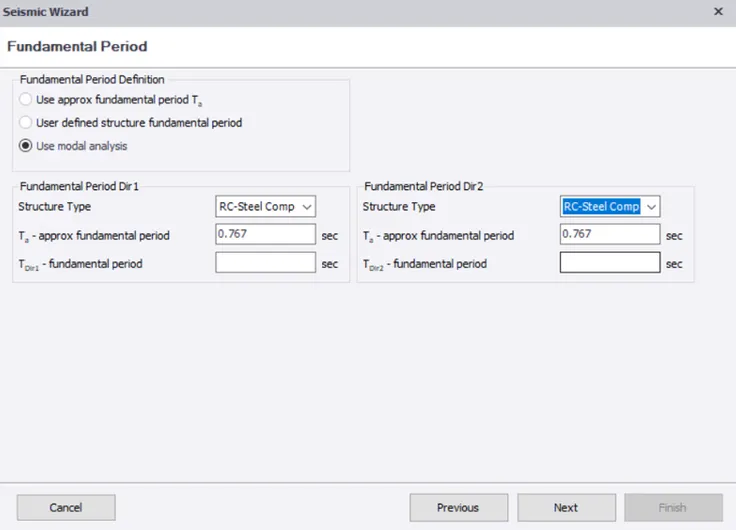
- Now select load cases and then select seismic load option and then we can see a pop up box
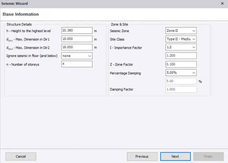
- Now check all the values displayed in pop up box
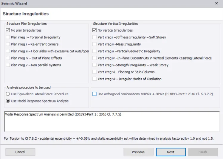
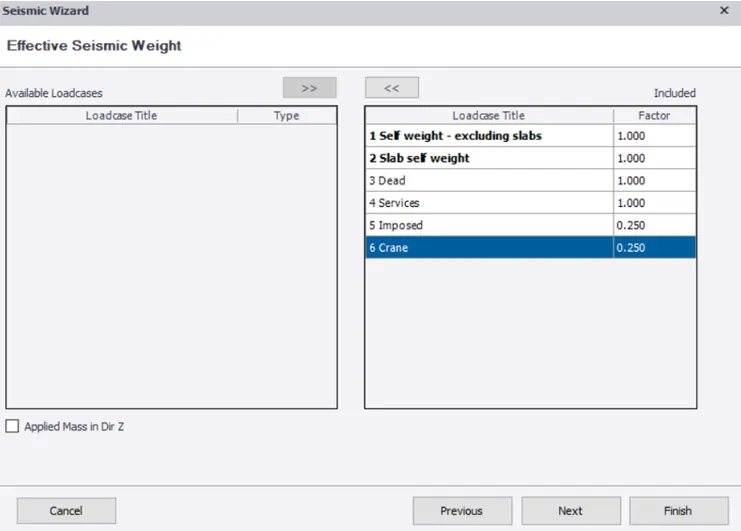
- Now click on next then another pop up box appears
- Then check length, width, height values once again and then select finish option
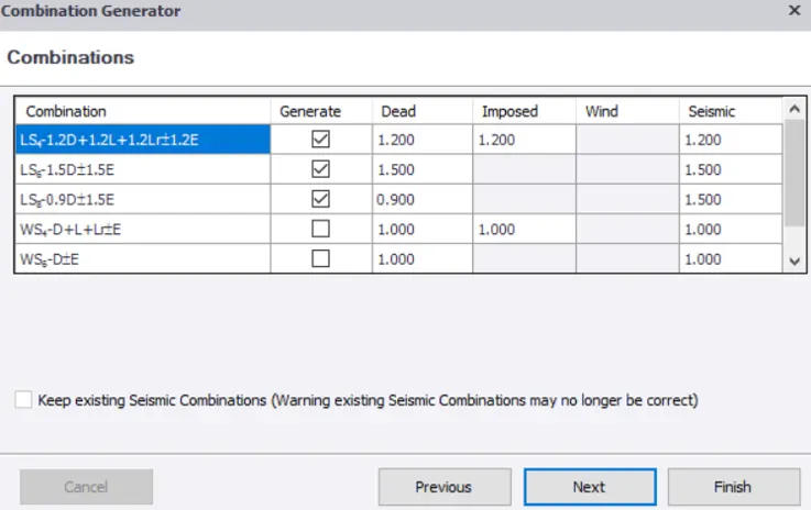
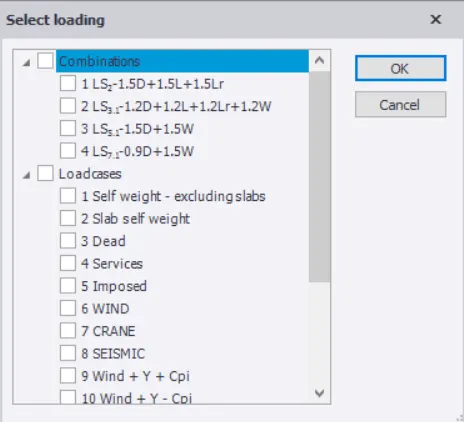
- Now select seismic loads that we have given to the structure from load tool bar which is located below project work space
- Now validate the structure to further verify any errors after applying loads
- Then if you found any errors after validation click on required error and rectify the error
- Rectify the error by changing the particular data to required data
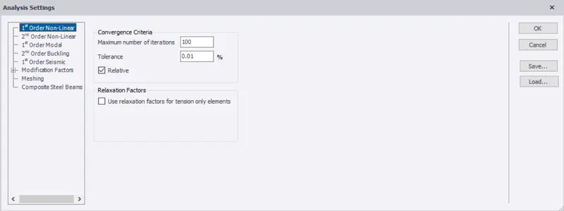
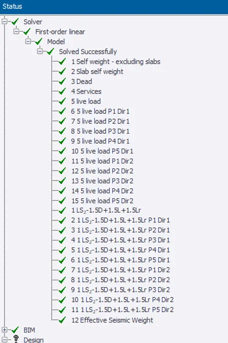
- Now select analyse tool from tool bar & then select 1st order linear option from it
- Then Analyse the structure, after analysis it shows the errors to be rectified again
- Then select required member to be rectified, then left click mouse, then we get a pop up box, from that select member option and under that select static option then we can see another pop up box
- Now we can find load analysis which can be done manually
- Now check the calculations of manually done load analysis and compare the value with IS Code
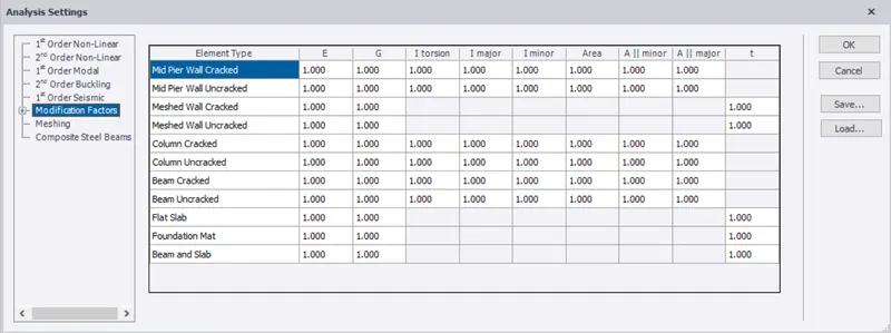
- Now set the size of structural members as required
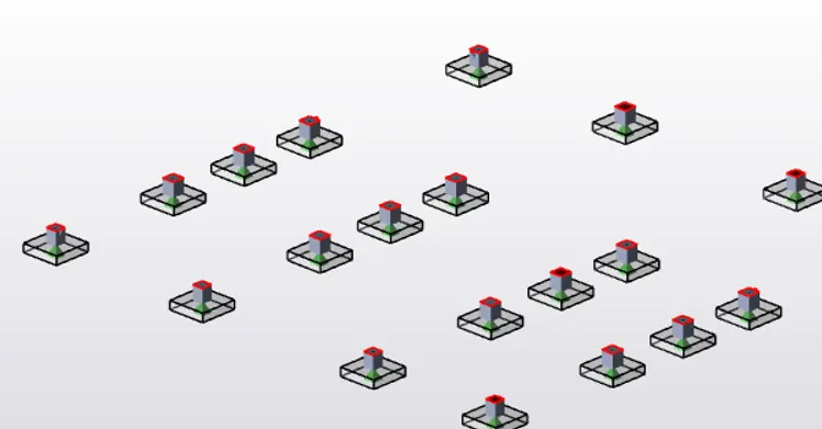
- Now design the foundations for the structural model
- Now select foundation tool from tool bar, then select the type of foundation to be designed
- Now select base level from project browser and apply foundation at base level
- Now right click on foundation member and then select design members & then static option
- Then a pop up box appears then check for any errors like its dimensions and grade of concrete
- Now apply same properties to all the foundations

RESULT : Therefore analysis of design the members and outline the thought process in selecting the member sizes along with the foundation design done successfully