Week 6 Challenge
- Summarize your study for the bending moment, shear force, and deflection diagrams for the elements of the model
A) AIM: To analyse the structure and summarize study for bending moment, shear force, and deflection diagrams for the elements of the model and also display these parameters for our model.
TOOLS REQUIRED:
FILE
OPEN
PROPERTY WINDOW
PROJECT BROWSER
RESULT VIEW
VALIDATE
SETTINGS
ANALYSE
1ST ORDER LINEAR
MODIFICATION FACTOR
LOAD COMBINATION BOX
MOMENT MAJOR
MOMENT MINOR
SHEAR MAJOR
SHEAR MINOR
DEFLECTION
PROCEDURE:
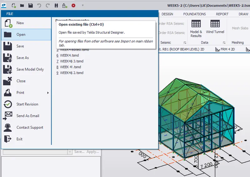
1. firstly let us analyse the structure and then check the bending moment, shear force, and deflection diagrams for the elements of the model for this let us primarily open the saved file in the Tekla software using the open icon present in the file toolbar.
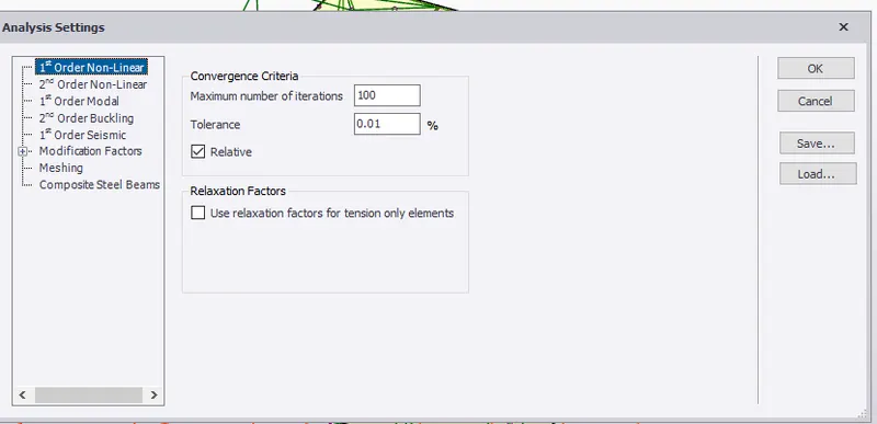
2. before performing analysis we have to check for some parameters for that let us select the settings icon present in analyse toolbar
3. a dialog box appears , click on 1st order linear and check for number of iterations and tolerance and can modify if required.
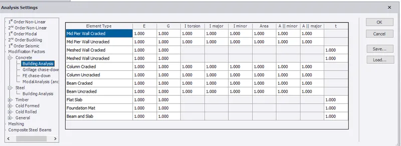
4.Then check for modification factor, by default these are 1 but if there is any other factor change it to 1
and click ok.
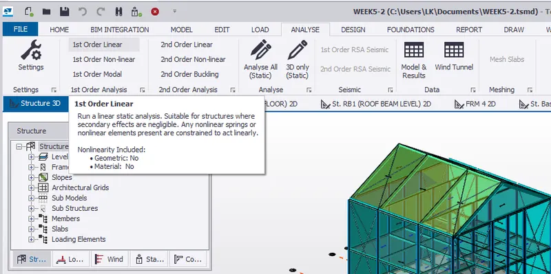
5.Once the file is opened for analyzing the model, select analyse icon and click on 1st order linear from the options available.
6. After clicking on 1st order linear a dialog box appears where we have to select load cases and load combinations and click ok.
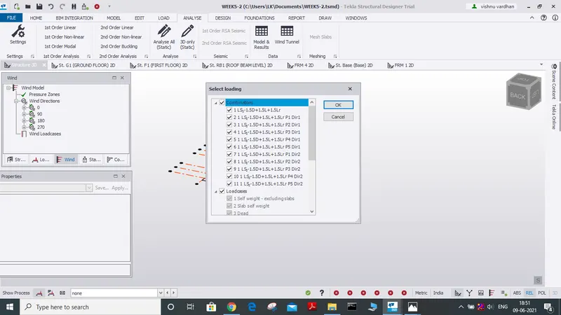
7. in this way we can analyze a structure simply, for that make use of the result view and we will get any of the required parameters for the analysis that includes (axial force, shear major, shear minor, torsion, moment major, moment minor can be accessed and also can check their values in different directions(X, Y, Z)
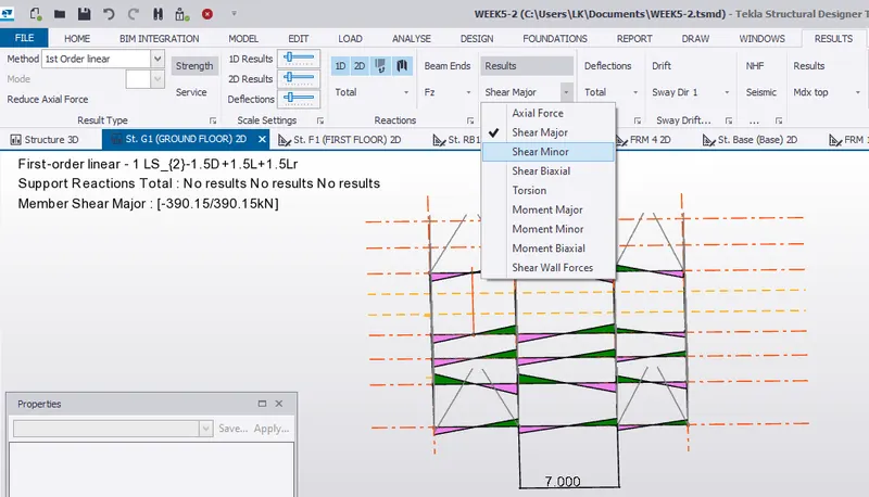
8. now by varying load combinations we can see different values of the parameters and we can modify the properties of the material for the worst-case values and modify its properties until all the load combinations will have satisfied the value of a parameter.
9. now le us check whether our analysis is right for this let us finish the above-mentioned steps now and check whether our model satisfies the load combinations so
once the above steps are done, select the solver option shown in the status menu of the project browser
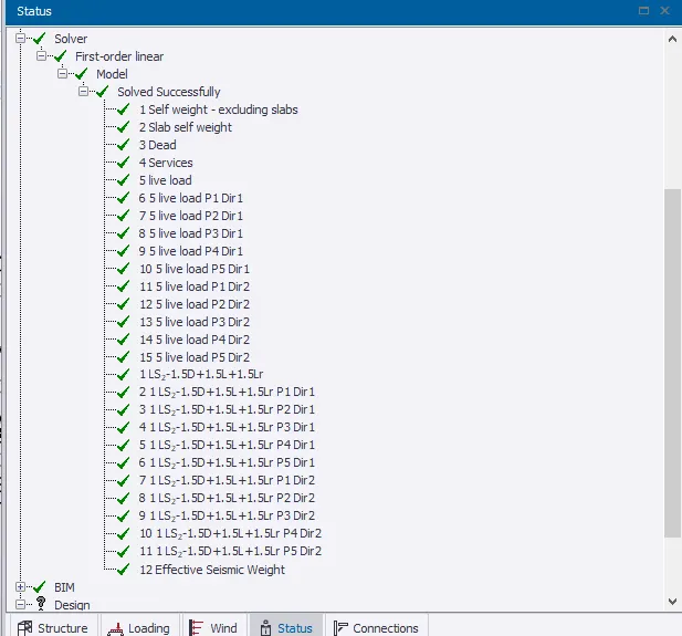
from here we can say that the model satisfies all the load combinations, if it fails in any of the load combinations we can alter the properties of the model and analyse once again.
Now let us summarise for the bending moment, shear force, and deflection diagrams for the elements of the model
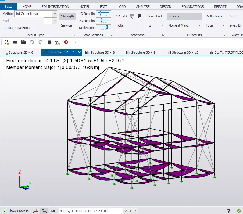
BENDING MOMENT: Bending moment can be defined as bending of the members due to the action of forces.
It is one of the most important parameter to be considered in the design.
By analyzing we could know the bending moment values for different load cases and is generally calculated by considering moment along all the sides of members To calculate the bending moment, the magnitude of the force is multiplied by the distance of the force from the point of support.
A beam may fail due to shear force before failure in bending.
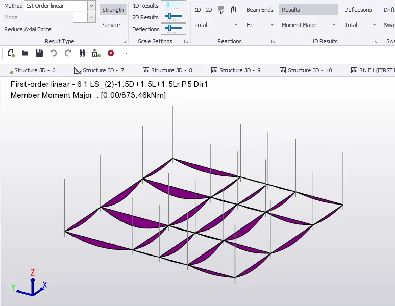
for finding the bending moment of the structure in Tekla software we must click on the result view of the created structure then select the moment minor /major option from the available option and we can observe bending moment by varying load combinations.
SHEAR FORCE: Shear force is defined as a force that acts in a direction parallel to a cross-section of a body, or simply we can say shear force is the unbalanced vertical force that is acting on to the right or left of the section.
the shear force at a section is an algebraic sum of the lateral forces acting on of all the sides of the section.
Shear force is also an important factor to be considered in the design of a model.
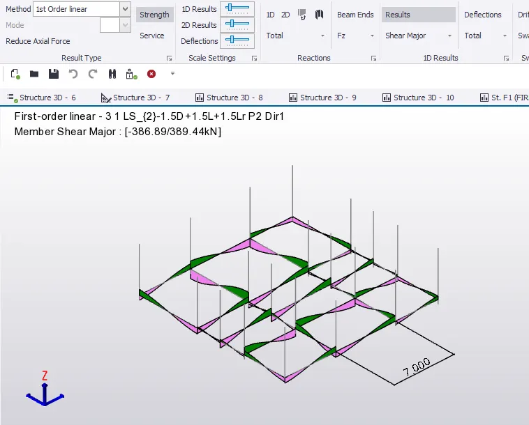
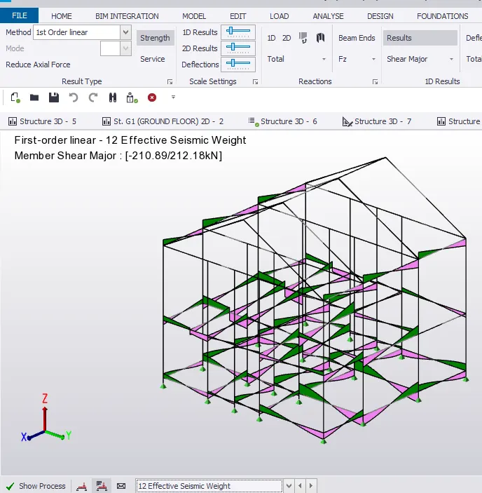
for finding the bending shear force of the structure in Tekla software we must click on the result view of the created structure then select the shear minor/major option from the available option and we can observe bending moment by varying load combinations.
DEFLECTION DIAGRAM: Deflection diagram can be simply explained that whenever a load acts on the member the member will deviate from its original position(might be a small value) that deviation is called as deflection and resembling deflection of a member is known as deflection diagram
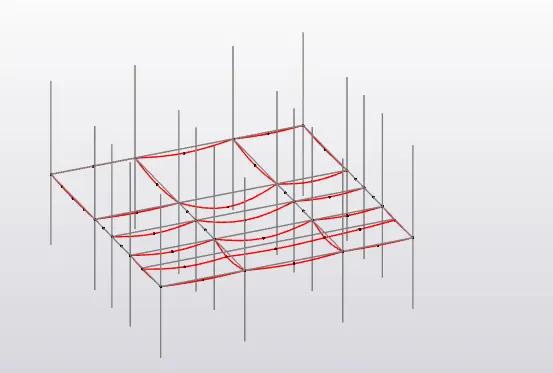
deflection to a certain extent is ok because when load is removed it comes back to its original position but when there is more deflection there is a possibility of failure of the member thereby failure of the structure.
for finding the bending shear force of the structure in Tekla software we must click on the result view of the created structure then select the deflection icon available and we can see different defection diagrams for the structure.
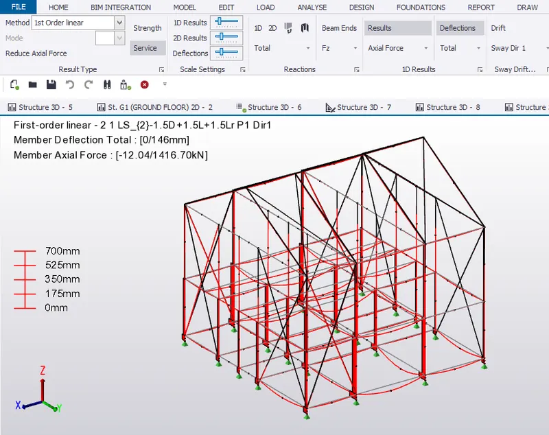
RESULT: WE HAVE SUCCESSFULLY ANALYSED OUR MODEL AND EXPLAINED HOW A MODEL IS ANALYSED
BY 1ST ORDER LINEAR ANALYSIS WHAT ARE SETTINGS TO BE MADE BEFORE PERFORMING ANALYSIS,
AND ALSO FOUND BENDING MOMENT, SHEAR FORCE, DEFLECTION OF THE STRUCTURE AND SUMMARISED
STUDY FOR bending moment, shear force, and deflection diagrams for the elements of the model
and also have displayed these parameters in our model for various load combinations
2. Based on the analysis design the members and outline the thought process in selecting the member sizes along with the foundation design
AIM: Based on the analysis design the members and TO outline the thought process in selecting the member sizes along with the foundation design.
TOOLS REQUIRED:
FILE
OPEN
PROPERTY WINDOW
PROJECT BROWSER
RESULT VIEW
VALIDATE
SETTINGS
ANALYSE
1ST ORDER LINEAR
MODIFICATION FACTOR
LOAD COMBINATION BOX
FOUNDATION
PILE BASE FOUNDATION
DESIGN MEMBER OPTION
COPY
EDIT
SAVE AS
REVIEW VIEW
RESULT VIEW
PROCEDURE:
1. Open the saved file in the Tekla software using the open icon present in the file toolbar.
2. before PERFORMING analysis we have to check for some parameters for that let us select the settings icon present in analyse toolbar
3. a dialog box appears, click on 1st order linear and check for the number of iterations and tolerance and can modify if required.
4.Then check for modification factor, by default these are 1 but if there is any other factor change it to 1
and click ok.
5.Once the file is opened for analyzing the model, select analyse icon and click on 1st order linear from the options available.
6. After clicking on 1st order linear a dialog box appears where we have to select load cases and load combinations and click ok.
8. in this way we can analyze a structure simply, for that make use of the result view and we will get any of the required parameters for the analysis that includes (axial force, shear major, shear minor, torsion, moment major, moment minor can be accessed and also can check their values in different directions(X, Y, Z)
8. now by varying load combinations we can see different values of the parameters and we can modify the properties of the material for the worst-case values and modify its properties until all the load combinations will have satisfied the value of a parameter.
9. now le us check whether our analysis is right for this let us finish the above-mentioned steps now and check whether our model satisfies the load combinations so once the above steps are done, select the solver option shown in the status menu of the project browser
from here we can say that the model satisfies all the load combinations.
if it fails in any of the load combinations we can alter the properties of the model and analyze it once again.
10) Analysis of the model is done. now let us suppose design beam for that select the beam which you are designing then right-click on the selected beam based on the analysis.
11) a large number of options will appear there we can select design/check member, after selecting design member two options will appear select static.
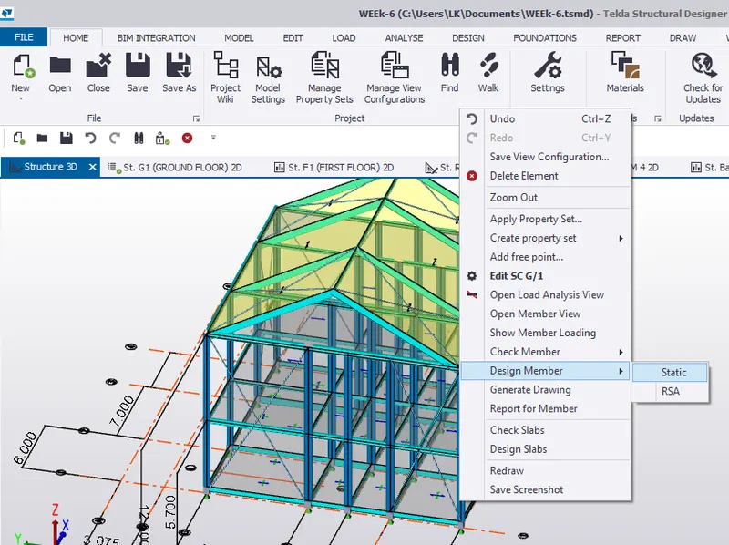
12. A new table appears stating whether the member satisfies the load combinations, forces, bending moment, axial force, etc
13. It is ok if the member passes the stated things but if it fails in any of the properties shown(load combinations, forces, bending moment), the member's properties must be modified.
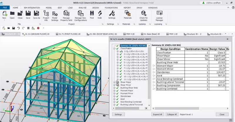
14. as here the member clears all the tests tells us that the member is suitable for the model and no need to change the member properties until it clears all the tests, similarly, we can do it with the remaining members.
15.now let us design the foundation for the model for this let us select the foundation icon present at the top.
16. after selecting foundation a number of type of modeling foundation will appear select anyone of them,
so let us select pile base column option

17.now with the help of project browser go to base level and apply foundation to the column
18. now right-click on that foundation member and select design members followed by static option
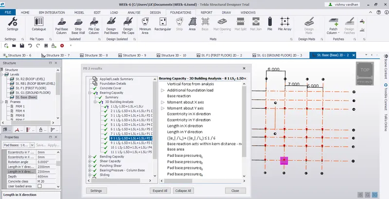
19. A new window opens check that whether the foundation member passes all the tests if yes ok, but if it fails any tests we have to change the properties of the foundation member like its dimension, grade etc.
20. with the same properties let us apply the foundation for the whole model simply copying it from the edit toolbar and then it asks for reference node select it and paste it at desired loactions
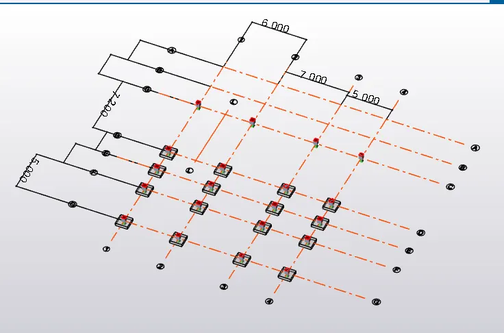
WE CAN MAKE USE OF SEEN CONTENT ICON FOR AN ISOLATED VIEW OF THE FOUNDATION
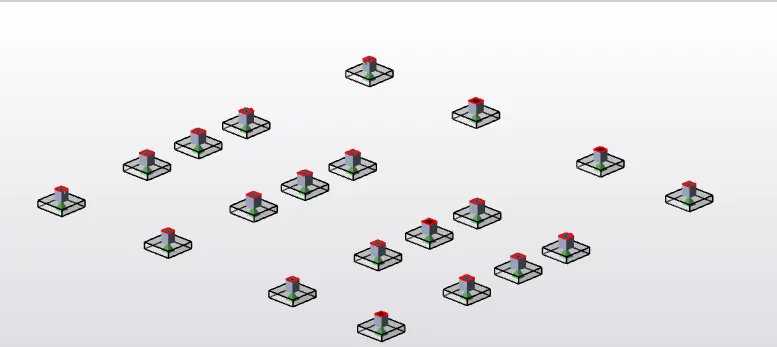
RESULT:
WITH THE ABOVE STEPS WE HAVE SUCCESSFULLY ANALYSED THE MODEL AND ALSO DESIGNED FOUNDATION MEMBER AND MODELED THE FOUNDATION MEMBER TO OUR MODEL
THE FINAL OUTPUT OF OUR MODEL IN 3D VIEW IS
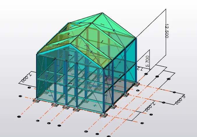
AND ALSO CHECKED THE COLUMN AND BEAM MEMBERS WHICH ARE ALREADY MODELED, WHETHER THE MEMBER PASSED THE TESTS CONDITIONS(LOAD COMBINATIONS, FORCES, BENDING MOMENT)