Week 6 Challenge
Q1 ) Summarize your study for the bending moment, shear force and deflection diagrams for the elements of the model.
ANS 1)
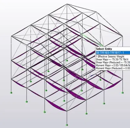
BENDING MOMENT : The bending moment can be defined as the bending effect which is caused due to any internal or external force. It is only of the important concept to be studied and bending moment plays an important role in the strength of the structure. In our software Tekla we have such advantages to finding the bending moment, which is used for adjusting and analysing of the structure. It can be calculated as the algebric sum of the moments about the section of all forces acting on either side of the section.
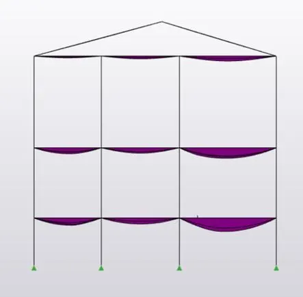
SHEAR FORCE : Shear force is a force acting in a direction that's parallel to a surface or cross section of a body, like the pressure of air flow over an airplane wing. It refers to the force acting along a surface. With in the beam, the shear force at any section is basically the algebric sum of the lateral forces acting on either side of the section. Calculation of the shear force is also important as it plays a vital role in alalysis of the structure.
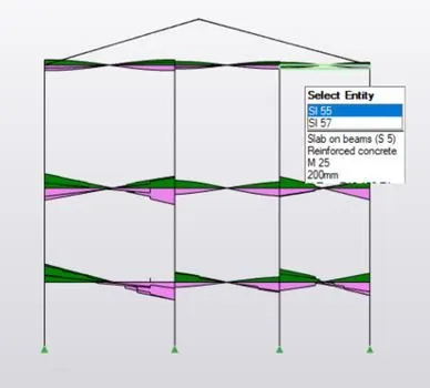
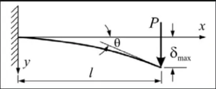
DEFLECTION DIAGRAM : In engineering, deflection is the degree to which a structural element is displaced under a load. The deflection distance of a member under a load can be calculated by integrating the function that mathematically describes the slope of the deflected shape of the member under that load. The degree of deflection increases with the distances between the supports or the amount of load applied on the member. The deflection diagram gives us a clear sketch about the load acting on the member.
Q2) Based on the analysis design the members and outline the thought process in selecting the member sizes along with the foundation design
ANS 2)
TOOLS USED :
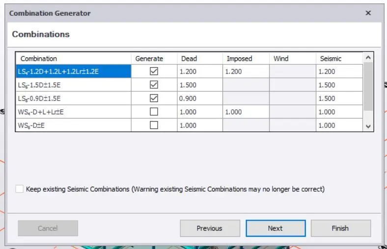
- Loads.
- Loadcases.
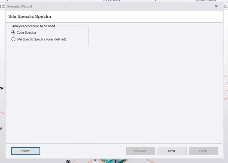
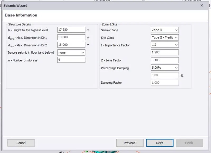
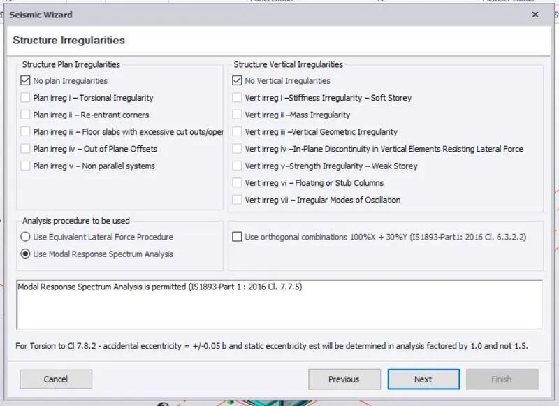
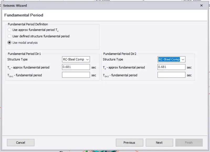
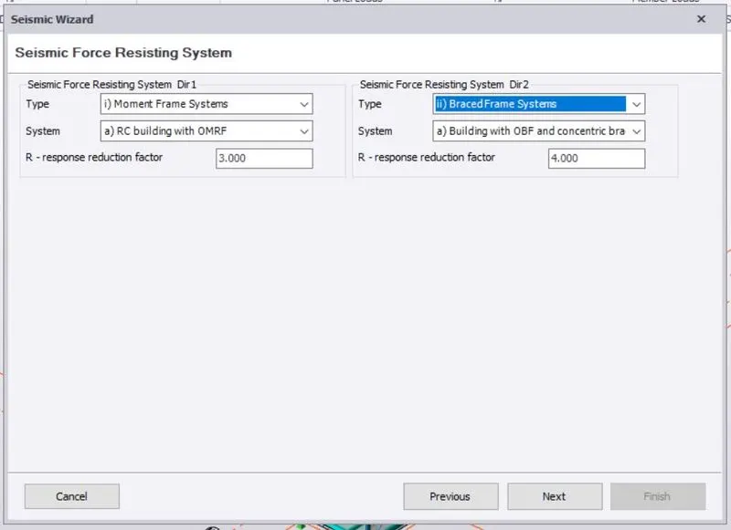
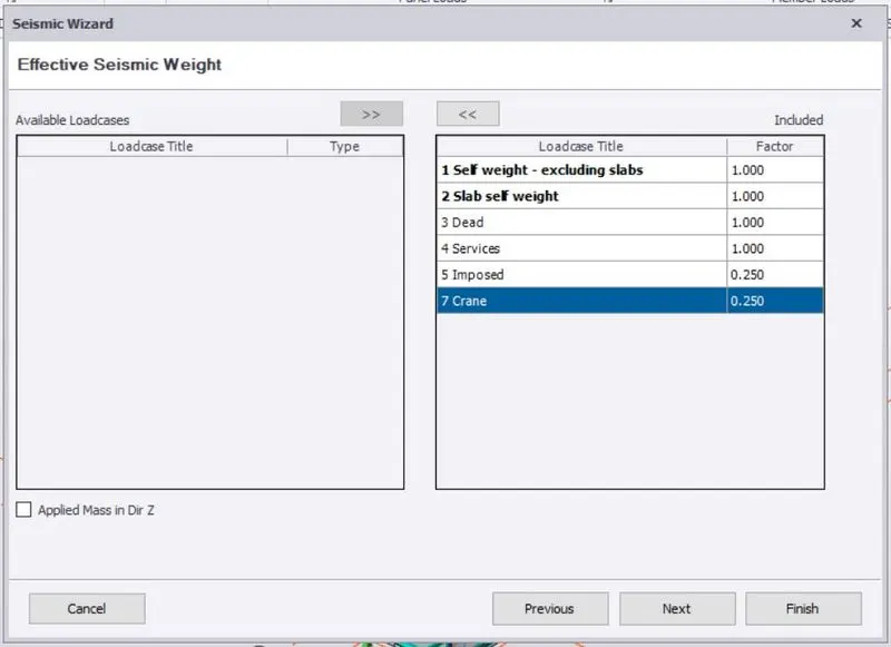
- Seismic load.
- Validate.
- Check member.
- Foundation.
- Properties.