REVIT_Usage of Elements & Properties_Week 3
ANS 1)
AIM :
Based on your previous layout add floor using floor option from architecture tab and set the thickness, and draw the grids for the ground plan.
TOOLS USED :
- Architecture.
- Floor.
- Levels.
- Grids.
- Material.
- Thickness.
- Property browser.
PROCEDURE :
- Open the project which was drawn in the previous session (or) draw a new plan layout.
- Add walls by using wall option from the architecture menu.
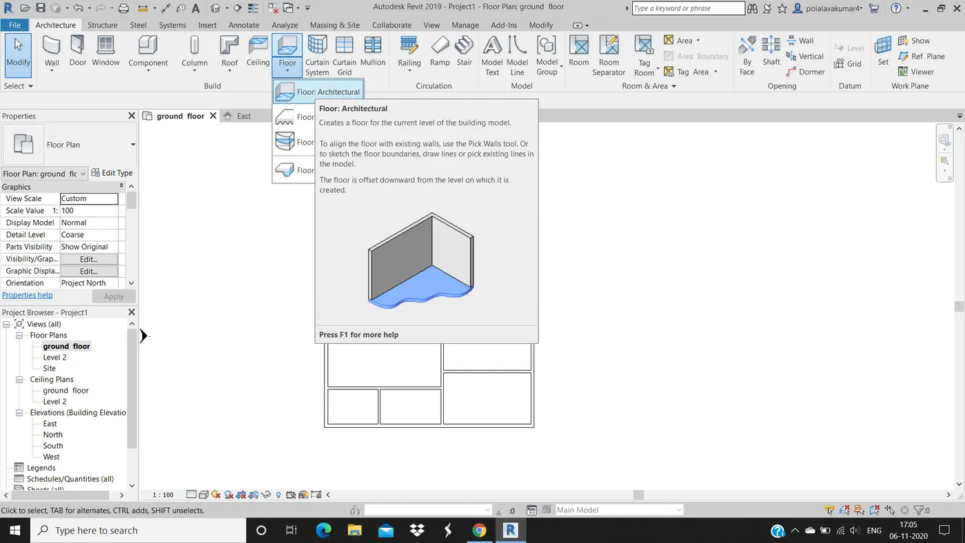
- From the architecture menu select floor tools and select pick lines option.
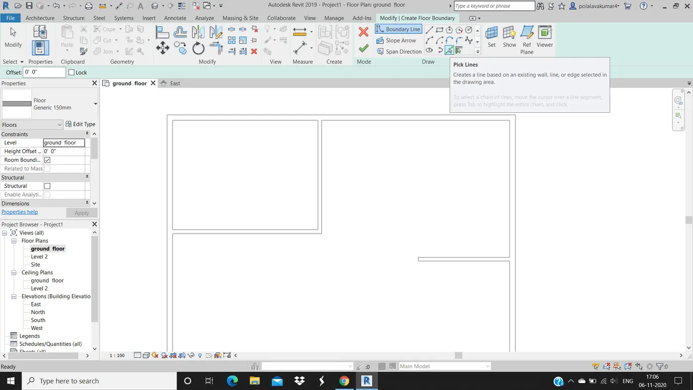
- With the help of pick lines option select the boundaries of the floor.
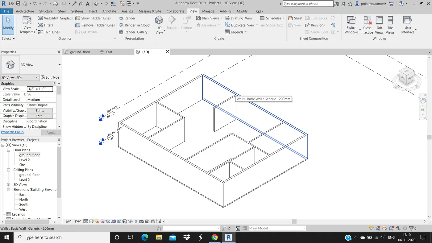
- Floor is created to our project.
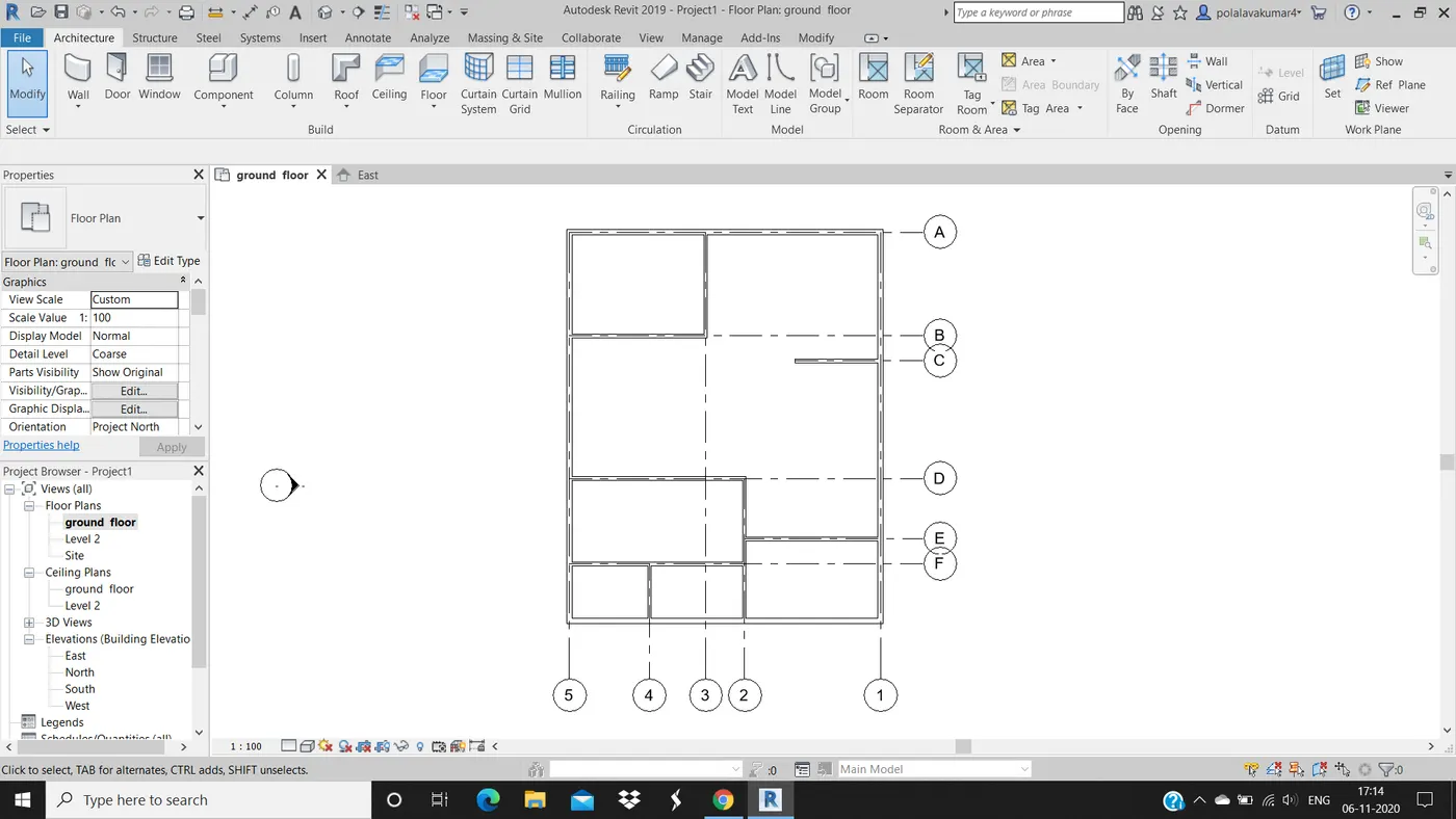
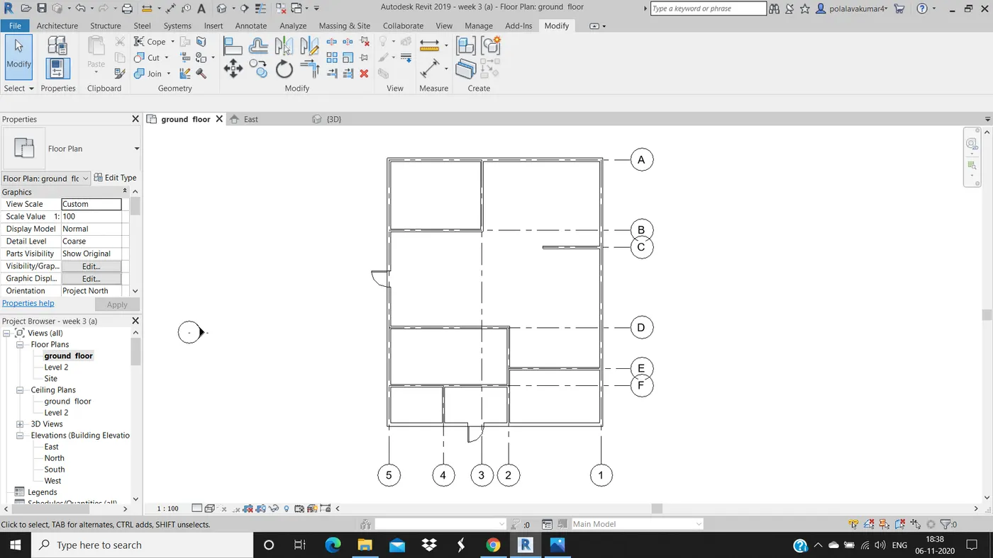
- From arcitecture menu select grids option and draw grid lines for all the walls.
- Horizontal grids lines to be named as A, B, C....
- Vertical grid lines to be named as 1, 2, 3.....
RESULT :
With the help of above steps we can draw floor for the previously created layout and draw the grid lines for the ground plan.
ANS 2)
AIM:
To add walls and modify the boundaries of the walls. Select appropriate thicknesss and material to the walls and floor.
TOOLS USED :
- Property browser.
- Level.
- View.
- Default 3d view.
- Edit type.
- Duplicate.
- Rename.
- Structure.
- Thickness.
PROCEDURE :
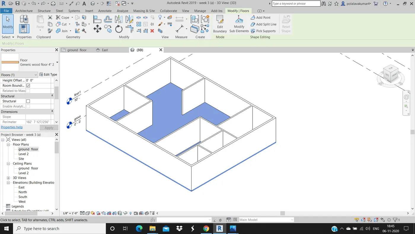
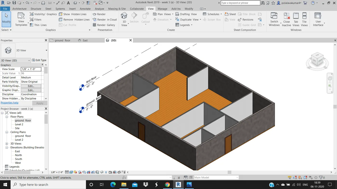
- Select the floor in the ground plan view.
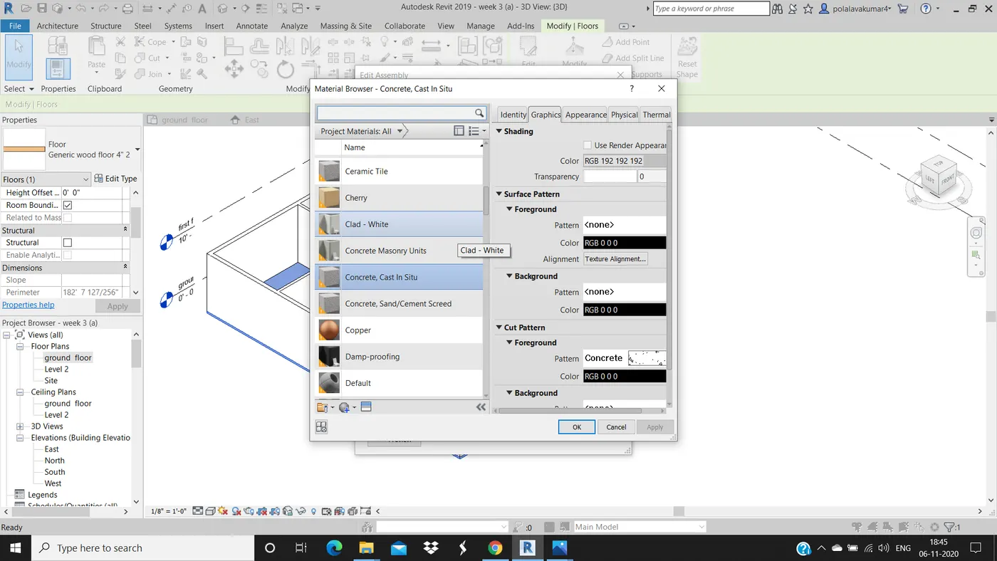
- Select properties and choose edit types.
- Select duplicate and give a desired name.
- Then select thickness and change it to the required thickness.
- Next select bt category in structure and select the desired structure of the floor.
- Repeat the same steps for walls also.
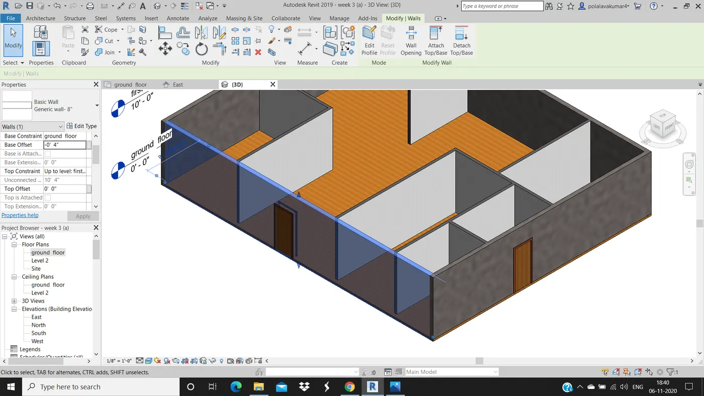
- At last select the wall and go to properties.
- Change the wall off-set to -4" so that it does not over lap with the 4" floor.
THEORY :
A) From my observation for connectiong walls rather than unconnected " up to level first floor" option is benefitial.
B) For modelling By height option is convenient.
RESULT :
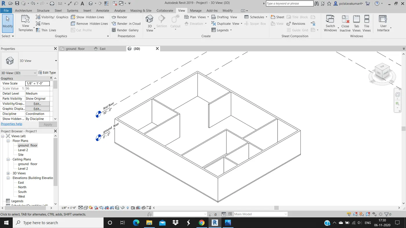
At lat we add the walls and floor and modify them by appplying the desired thickness and structure.
ANS 3)
AIM:
To copy the model elements from the ground floor to the second floor using copy and paste option from the modify menu.
TOOLS USED :
- Modify.
- Copy.
- Copy from clipboard.
- Paste.
- Paste from clipboard.
PROCEDURE :
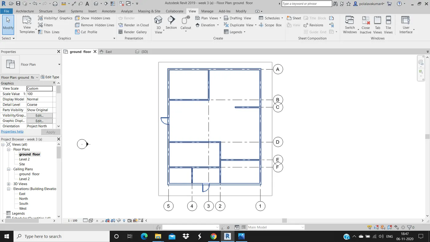
- First draw the layout in the ground floor plan.
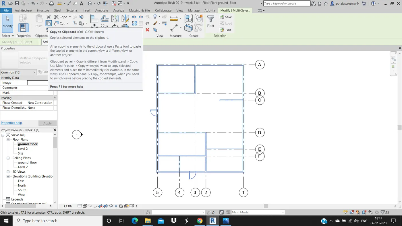
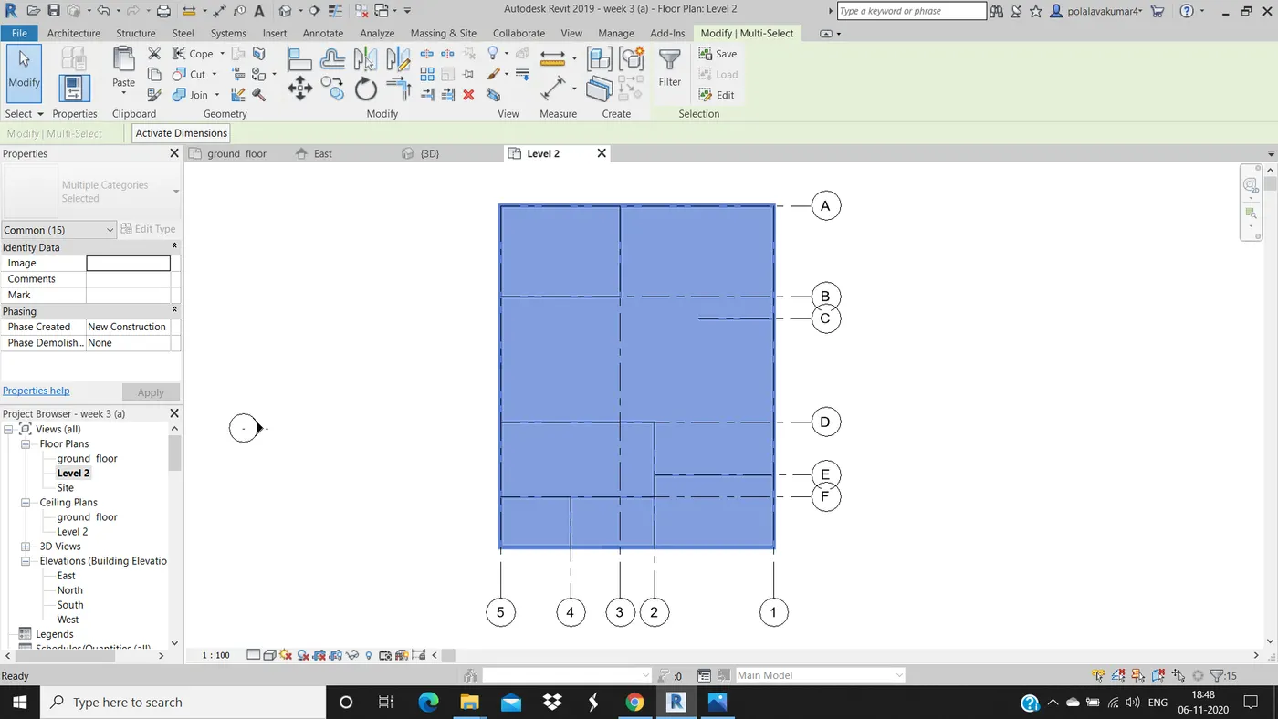
- With the help of mouse select the required things to be copied to the second floor.
- After selecting the required things go to modift menu and select copy to clipboard option.
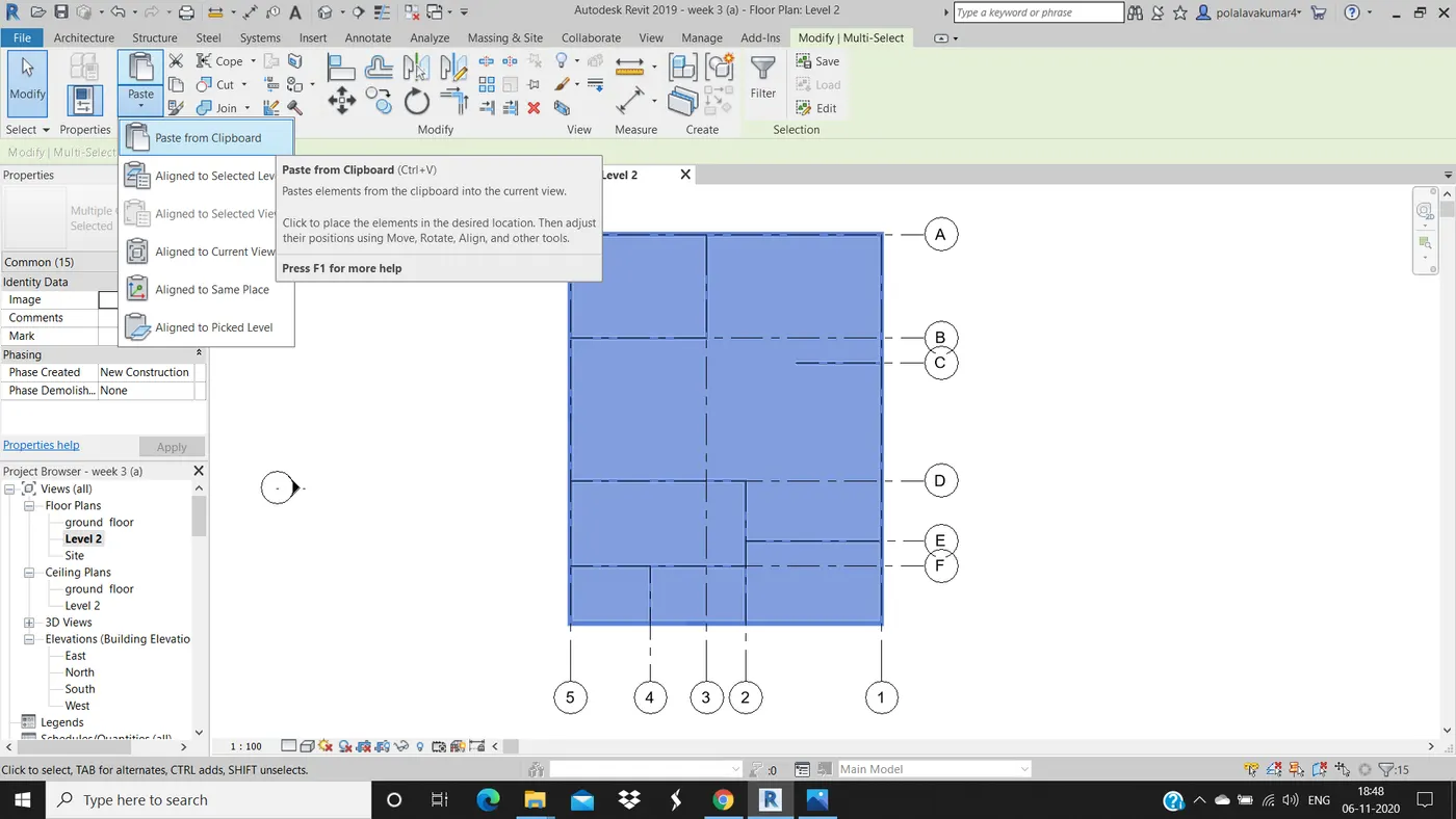
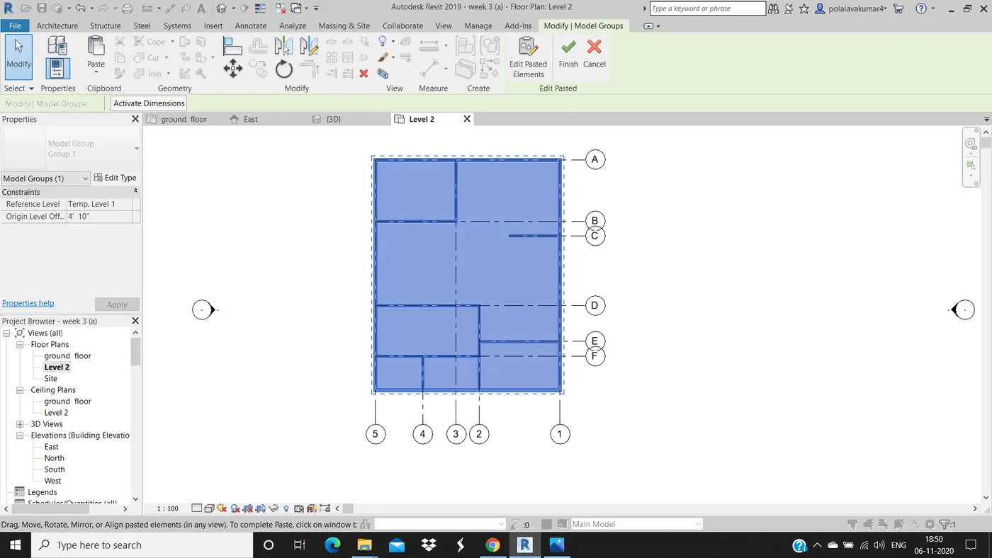
- Later in the property browser click on paste and select paste from clipboard optioin to paste the required things to the second floor.
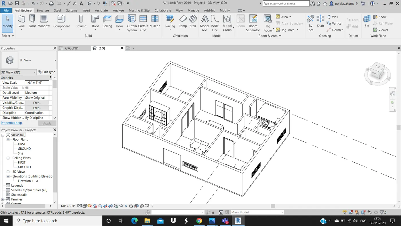
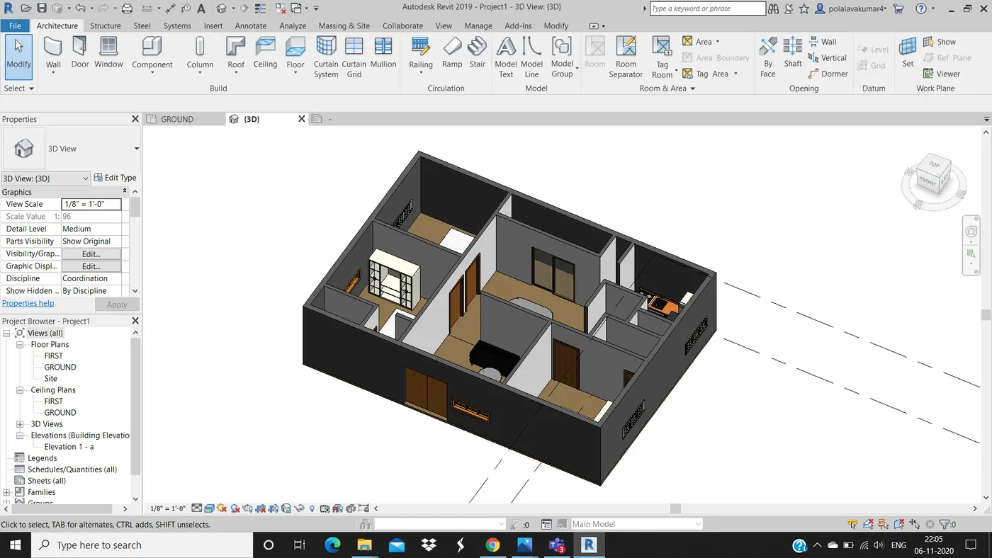
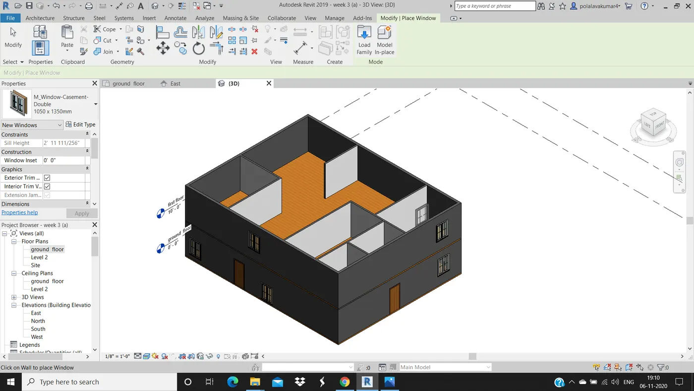
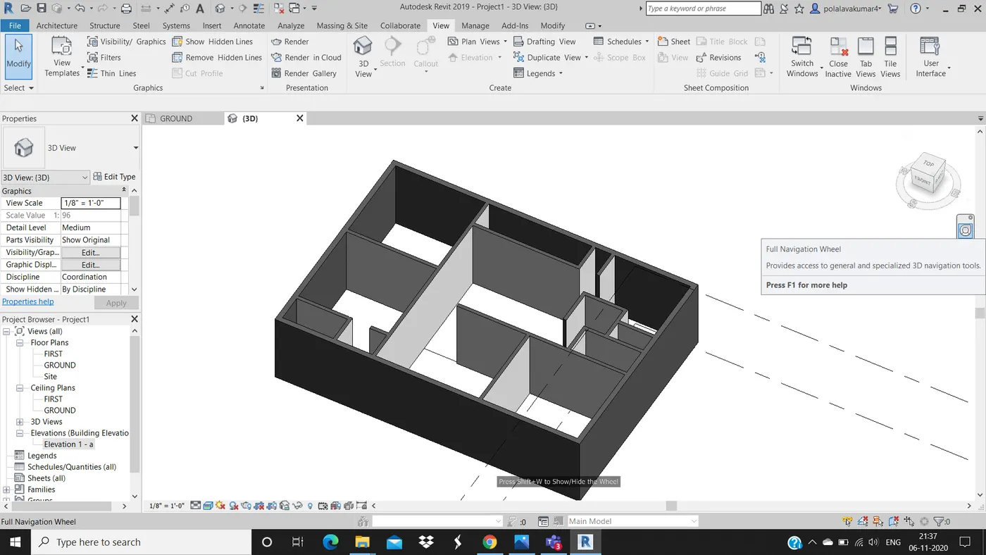
- Then select default 3d view from the view menu and see the two floor structure in 3d view.
RESULT :
With the above steps we can copy the desired components from level 1 to level 2 using the copy and paste from clipboard option.
ANS 4)
AIM :
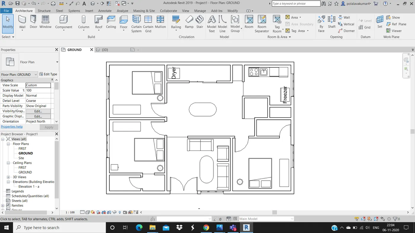
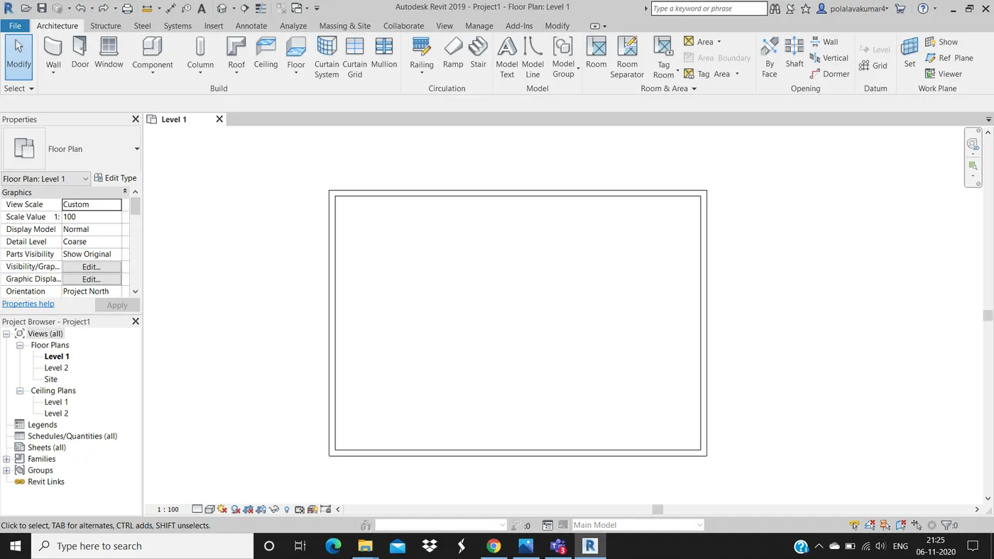
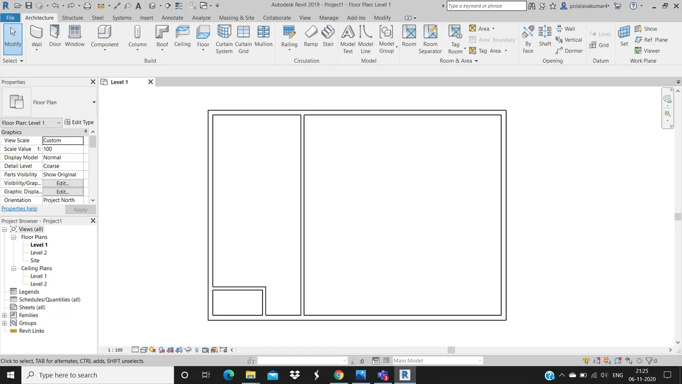
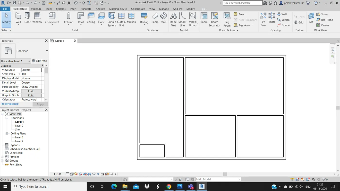
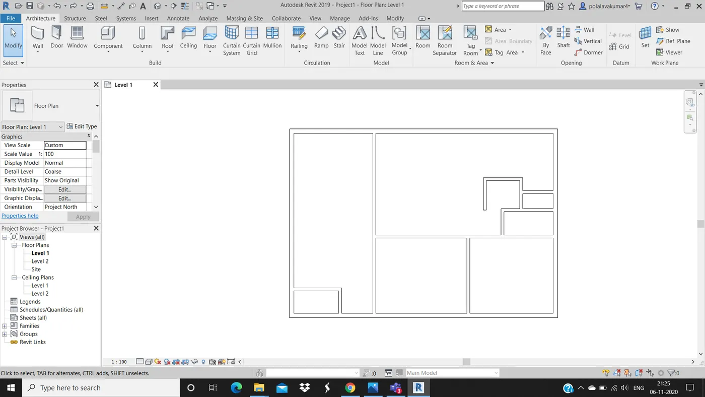
To draw a residential building of our own with outer walls for the layout and inner partition walls. Convert units if required.
TOOLS USED :
- Architecture.
- Wall.
- Trim.
- Room tag.
- Room seperator.
- Floor.
PROCEDURE :
- Open revit 2019 and open a new architectural template and click on ok.
- Go to architecture menu and select wall tool.
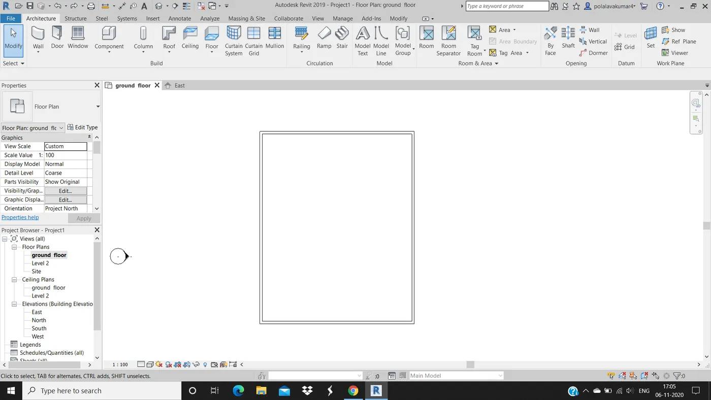
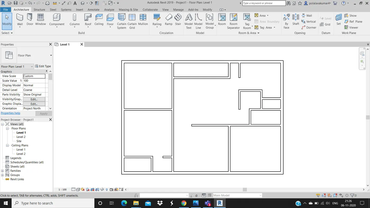
- For the outer walls use 200 mm and for the inner partition walls use 135 mm so as that it becomes easy in differentiating.
- Start the plan with outer walls.
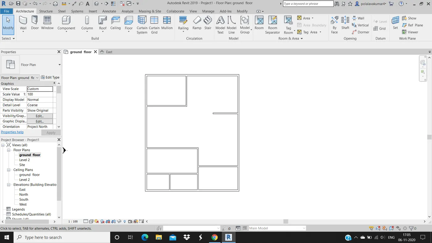
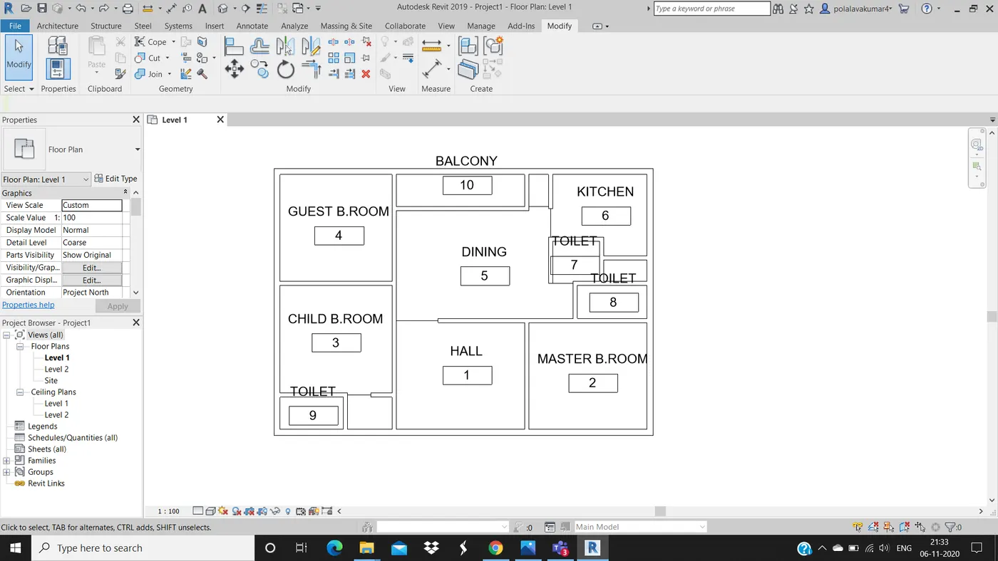
- Then with the help of inner partion walls create rooms.
- Use trim option to remove unwanted walls.
- Use room seperators and room tags to name them.
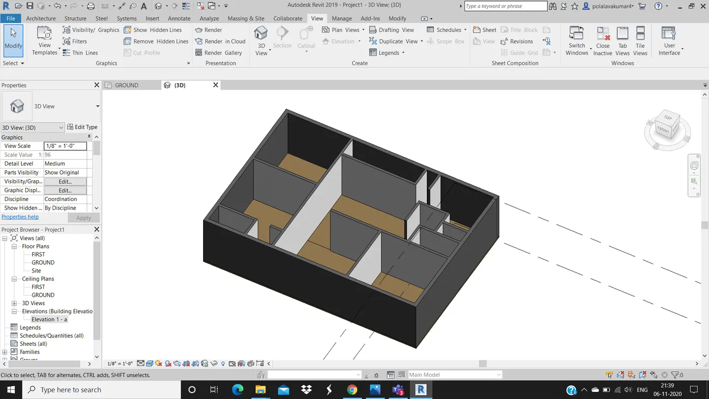
- At last select floor tool from the architecture menu and draw a 4" thick floor.
- Change the visual style to realistic to improve the project appearence.
RESULT :
We will be successful in desinging walls for the layout of our own choice and add floor to the residential building.
ANS 5)
AIM :
To add components to the plan created in the second week at appropriate locations in the plan of residential building.
TOOLS USED :
- Revit library.
- Revit family.
- Insert.
- Load families.
- Rotate.
- Move.
- View.
- Default 3D view.
- Doors.
- Window.
- Components.
PROCEDURE :
- First select the plan layout in which the walls are present.
- Then click on insert menu and click on load families.
- We have to download some revit content in order to get access of the families.
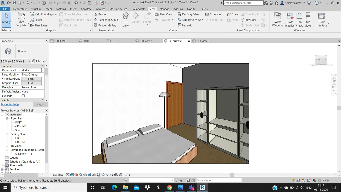
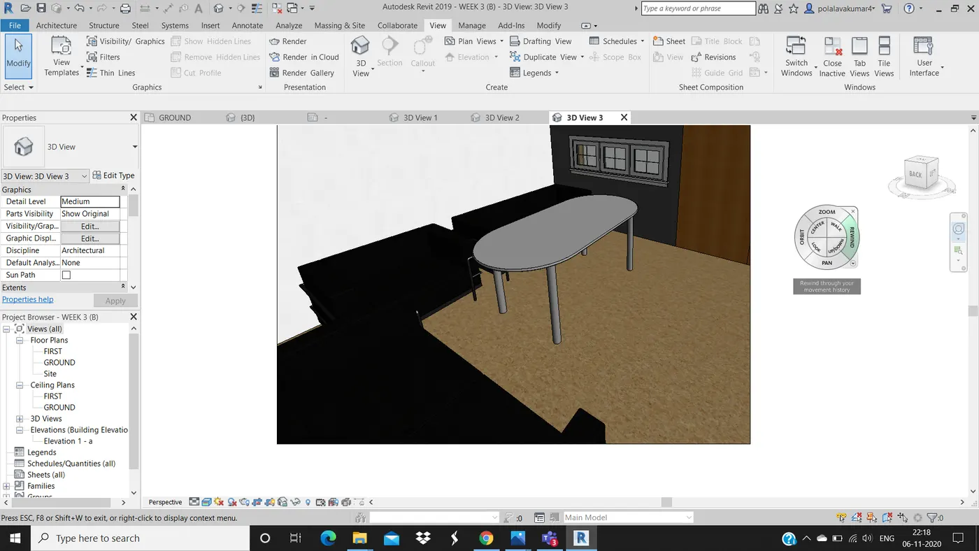
- We ahve to first load the families and then click on doors tool for doors, window tool for window and component tool for all the remaining components.
- We can use rotate and move tool from the Modift menu which can be used to move and rotate the components.
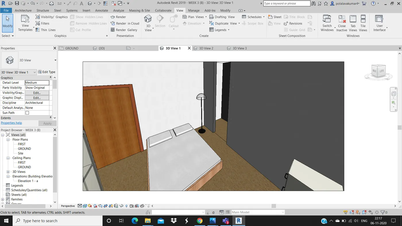
- Then click on camera view from view menu in order to get camera 3D view inside the projeect.
RESULT :
With the above steps we are successful in adding the components into the project at appropriate locations.