REVIT_3D Rendering of a House plan_Project 1
QUESTION 1) Based on the project saved from Week 3, proceed from First Floor Level .Model a Ceiling from architecture tab above the walls at first floor level.
ANS 1)
AIM :
To model a celing to the previously created project with the help of architectural tab above the walls at first floor level.
TOOLS USED :
- Architecture tab.
- Ceiling.
- Sketch ceiling.
- Pick lines.
PROCEDURE :
1. First open the previous project where we have completed the ground and first floor.
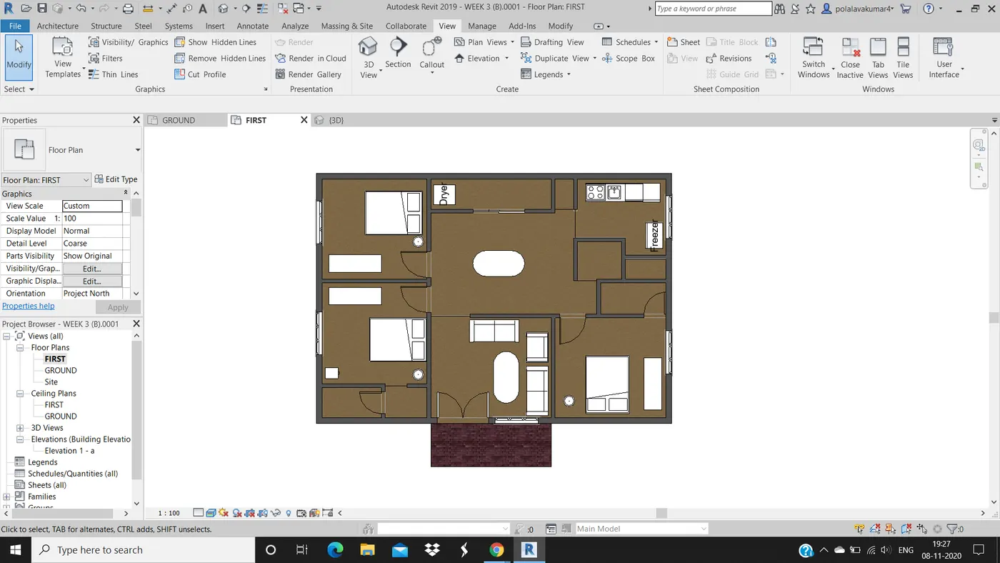
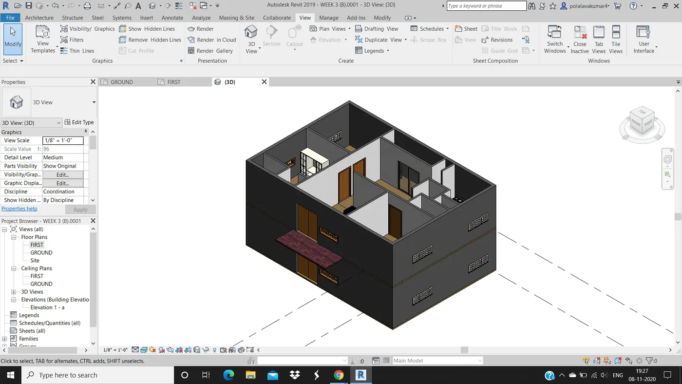
2. Go to architecture tab and select ceiling option.
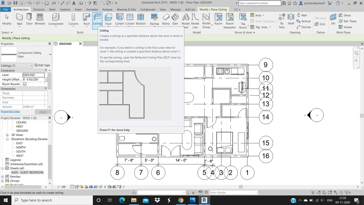
3. After that click on sketch ceiling and select on pick lines option to select the boundary lines for the ceiling.
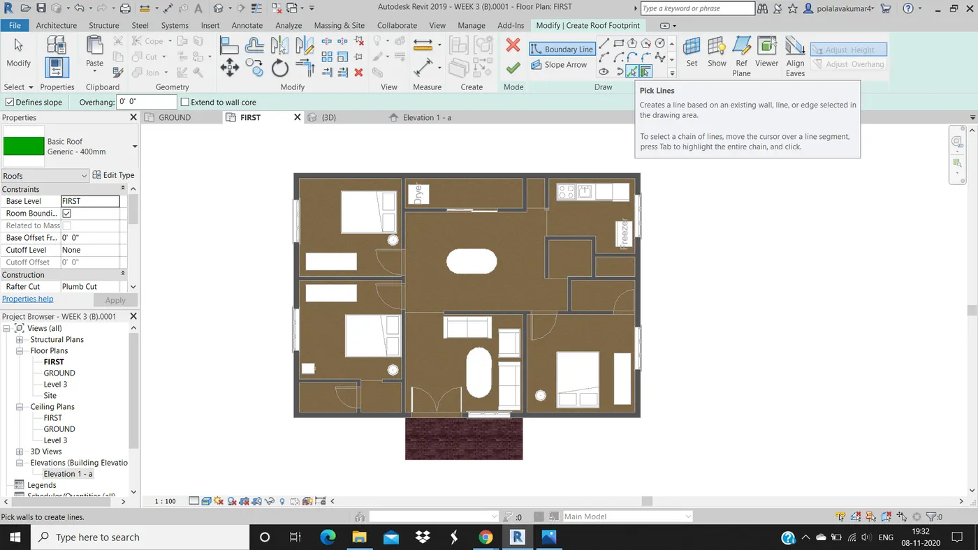
4. Then select the boundary lines and click on the tick mark on the ribbon.
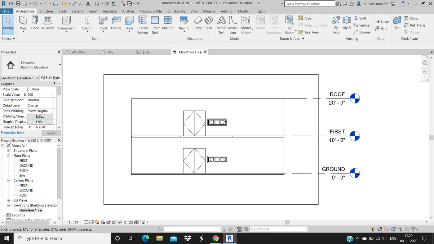
5. After that we will get the ceiling component constructed to the project.
RESULT :
We will model a ceiling from architectural tab above the walls at first floor level to the previous project saved from week 3.
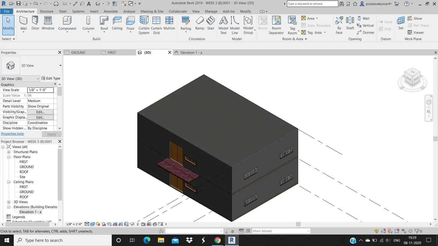
QUESTION 2) Model a roof above the ceiling by selecting the footprints of ceiling. Using the adjustment tool bars appearing on screen adjust the roof slope to 10 degrees.
ANS 2 :
AIM : To model a roof to the structure created using architecture tab and adjusting the slope of the roof to 10 degrees.
TOOLS USED :
- Architecture.
- Roof.
- Pick lines.
- Properties.
- Slope.
PROCEDURE :
1. First open the drawing where the project is there and where the roof should be added.
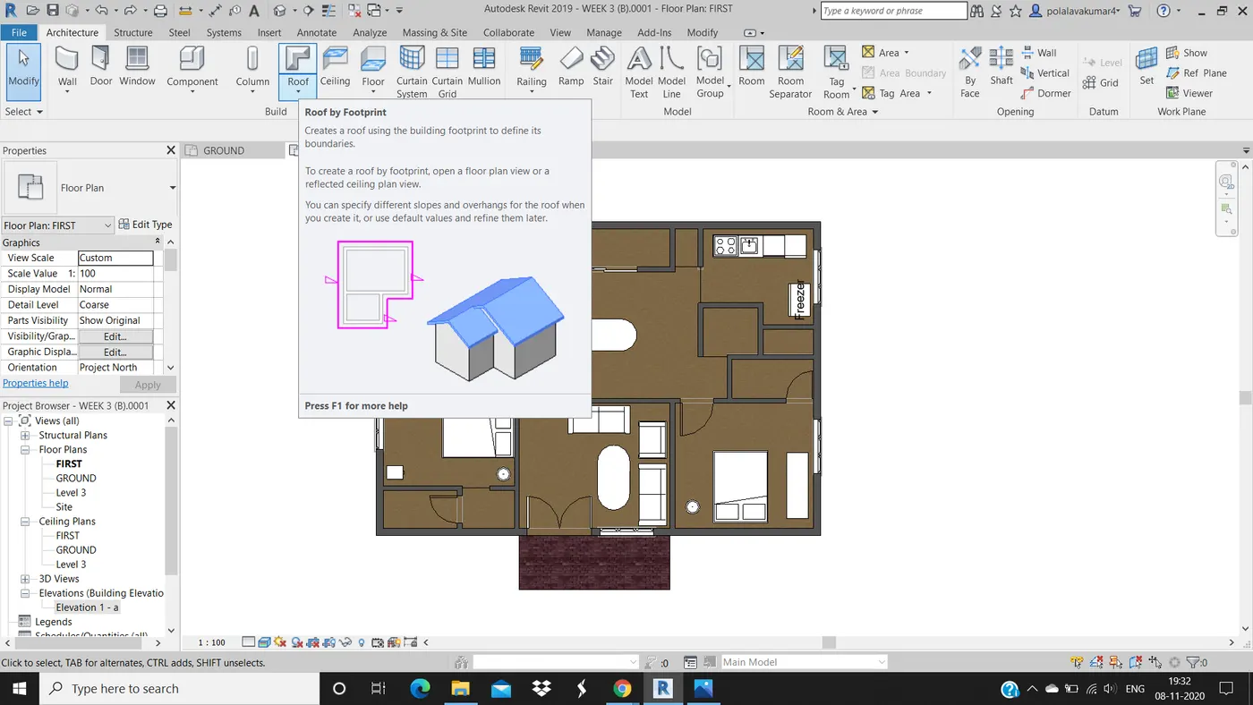
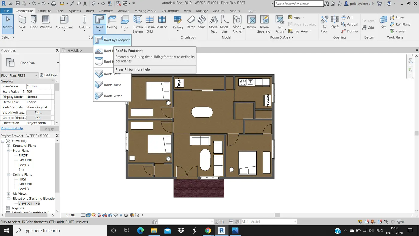
2. Go to architecture tab and select roof tool.
3. Click on roof by footprint option.
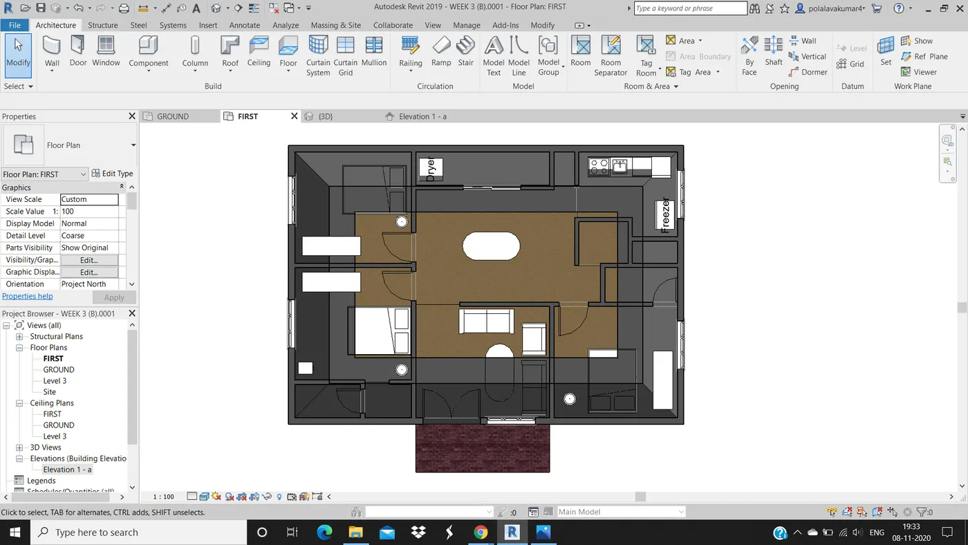
4. Then select pick lines option and select the boundary lines where the roof component should be added.
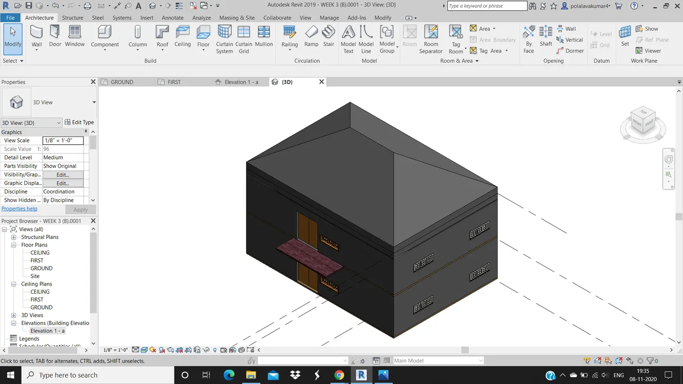
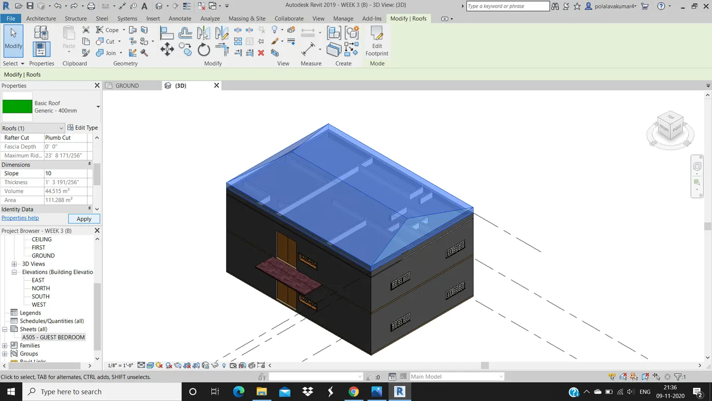
5. Select the roof and go to properties and select roof option and enter the vakue of sloope as 10 and click on ok.
RESULT :
With following the above mentioned steps we can add the roof component to the structure and adjust the slope to 10 degrees with the help of properties option.
QUESTION 3)
Using the file saved from week 2 to 4, create plan views for ground floor level and first floor level including all the walls , floors and components. Separate them to
architecture and structural plans.
a. Architecture plan must have walls , floors and all the components placed within the building.
b. Structure plan must have details of only walls, floors and columns.
ANS 3)
AIM : To create the plan views of ground floor level and first floor level includind walls, floors and components.
TOOLS USED :
- Property browser.
- Floor plans.
- Ground.
- First.
PROCEDURE :
1. Open the project where the ground and first floor plans are there.
2. From property prowser select floor plans.
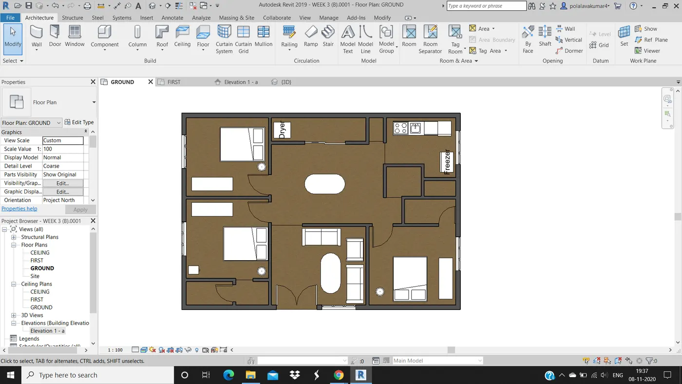
3. In that select ground floor plan and click on ground for ground floor plan.
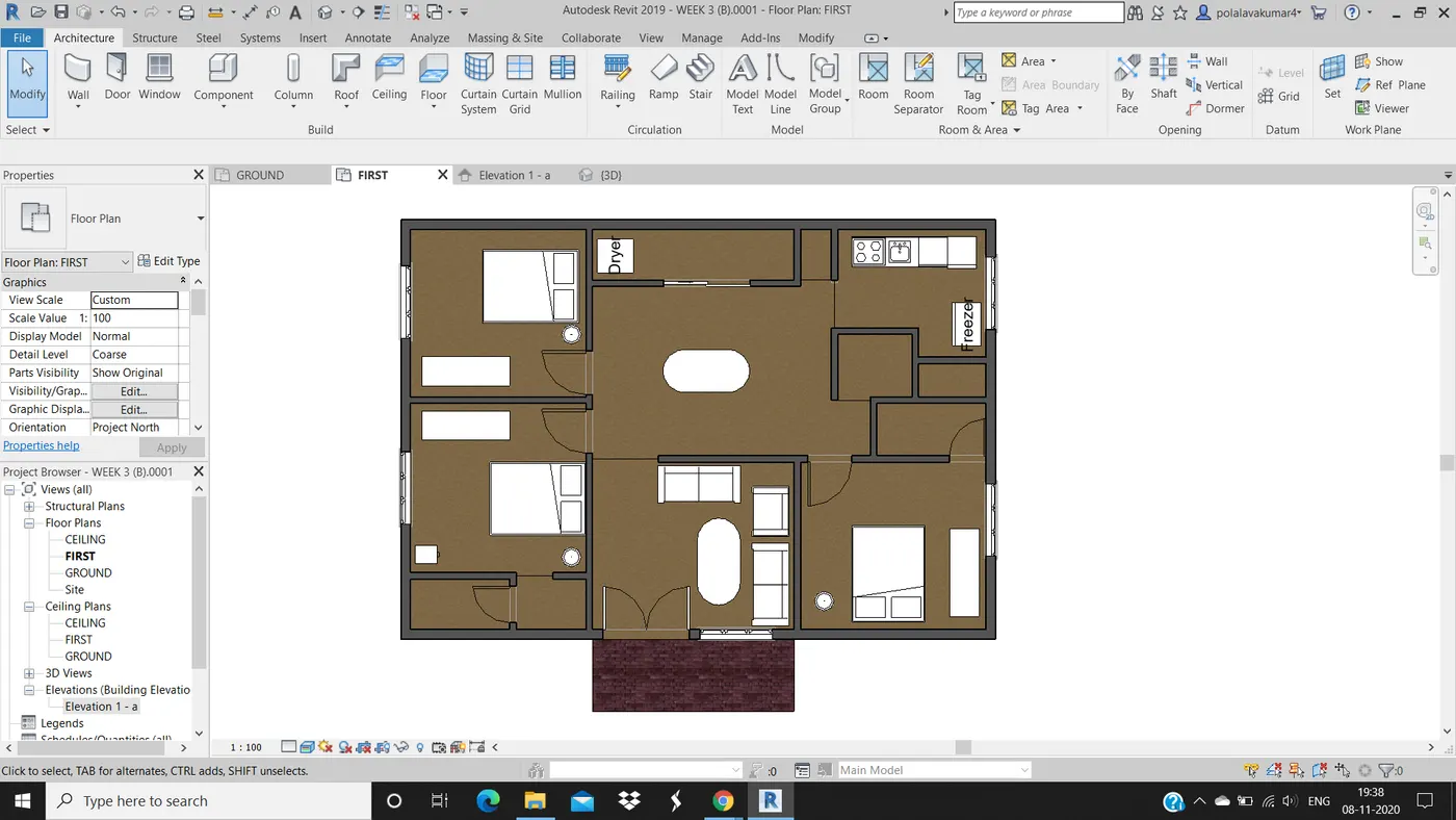
4. For the first floor plan click on the first floor plan to view the floor plan.
Structure plan views were not explained in the session.
RESULT :
With the help of the above steps we can achieve the ground and first floor plan.
QUESTION 4)
Using annotate tool bar add dimensions to all the walls and floors with reference to the longitudinal and transverse grids created in the project file.
a. The architecture plan dimensions include details on where the components are placed within the buildings with relation to grids. Overall dimensions are sufficient for architecture plans.
b. The Structure plan dimensions must include details on position of all the walls and interior walls with reference to grids. Locate all the framing components of the building with reference to a fixed point using Structural plans.
ANS 4)
AIM : Add dimensions to the walls and floors with reference to the longitudinal and transverse grids created in the project file.
TOOLS USED :
- Architecture.
- Grids.
- Annotate.
- Aligned.
PROCEDURE :
1. Go to architecture tab and select grids option.
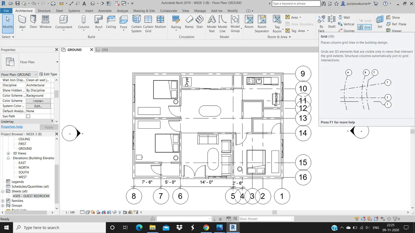
2. With the help of grids option draw the longitudinal and transverse grid lines.
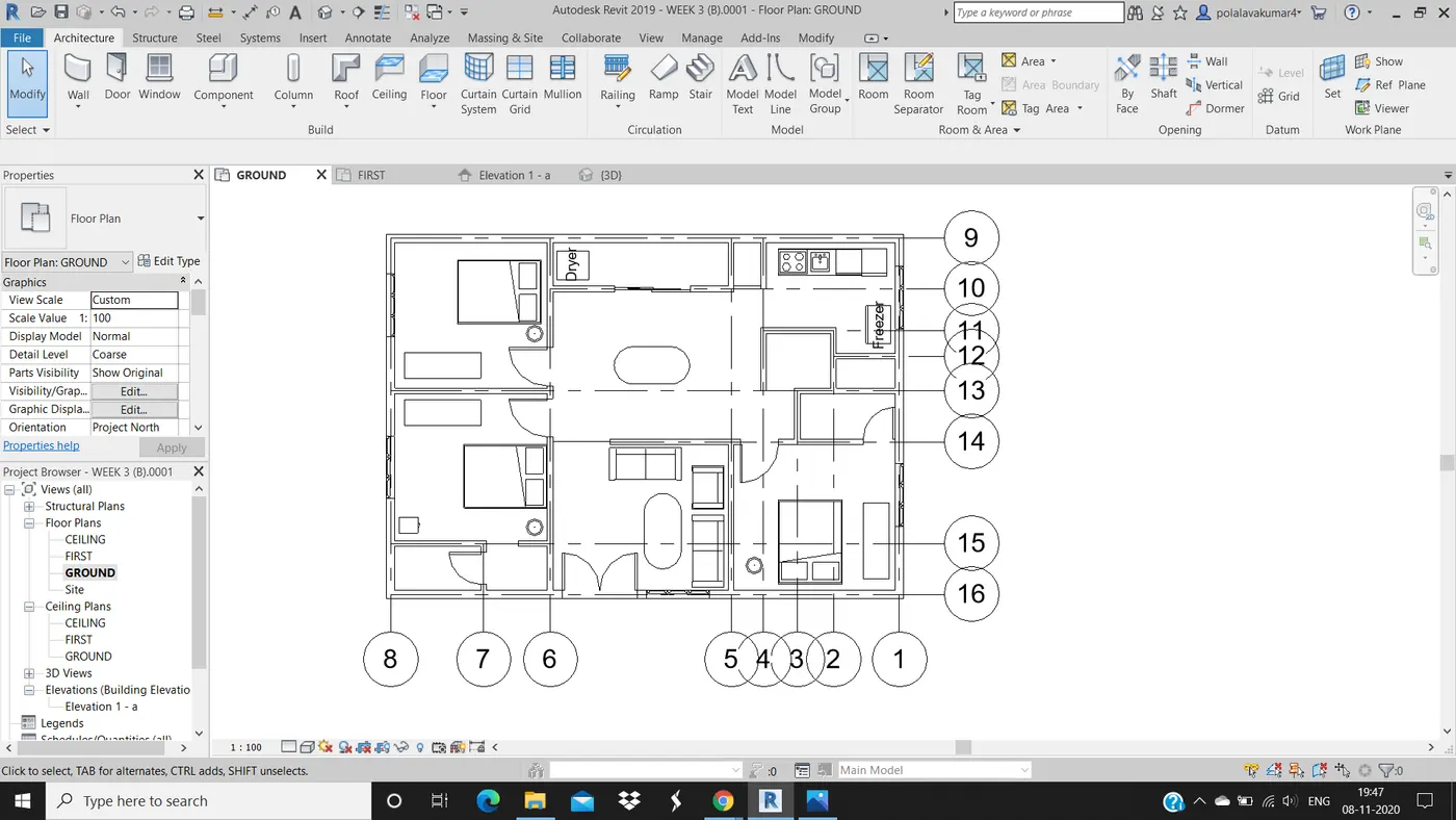
3. For naming of horizontal grid lines use A,B,C... from top to bottom.
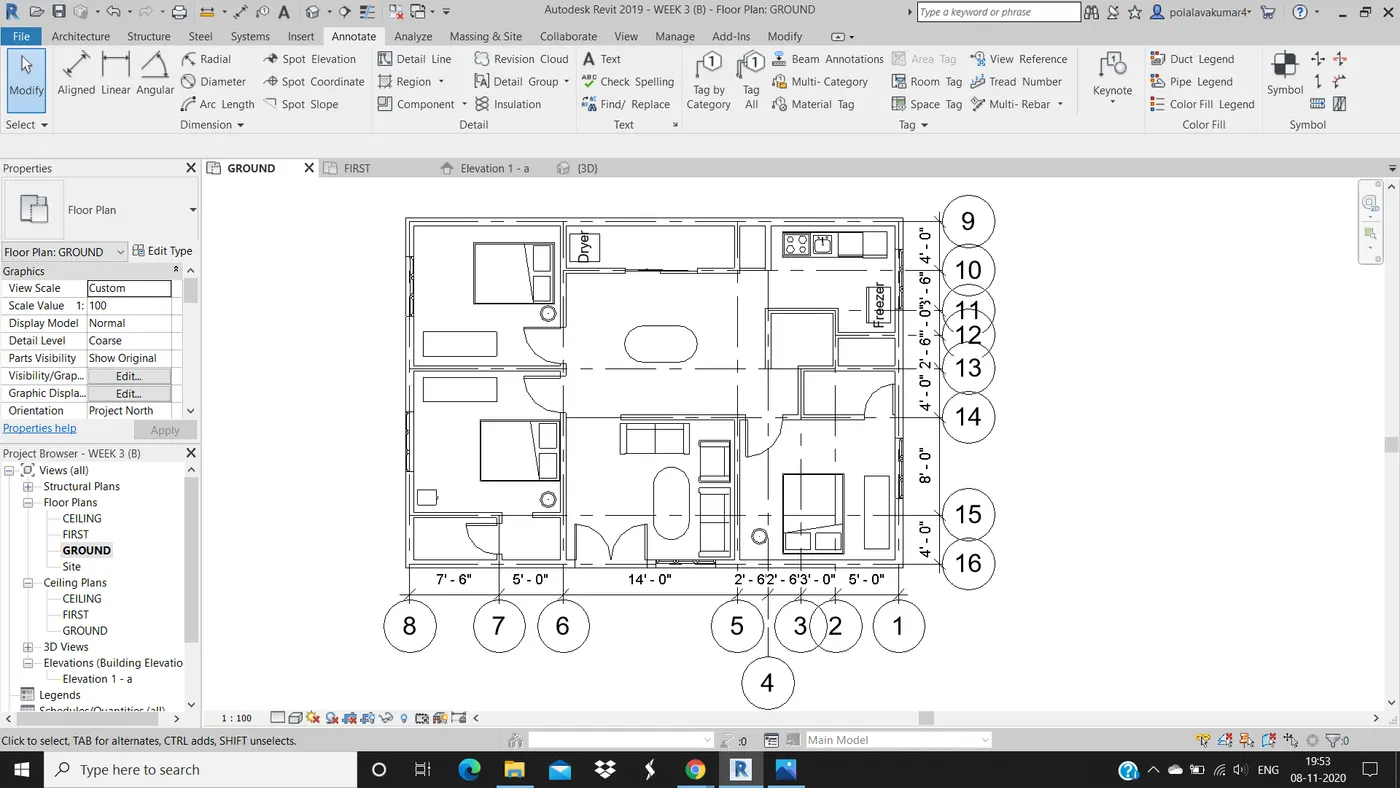
4. For naming of traverse grid lines use 1, 2, 3...... from right to left.
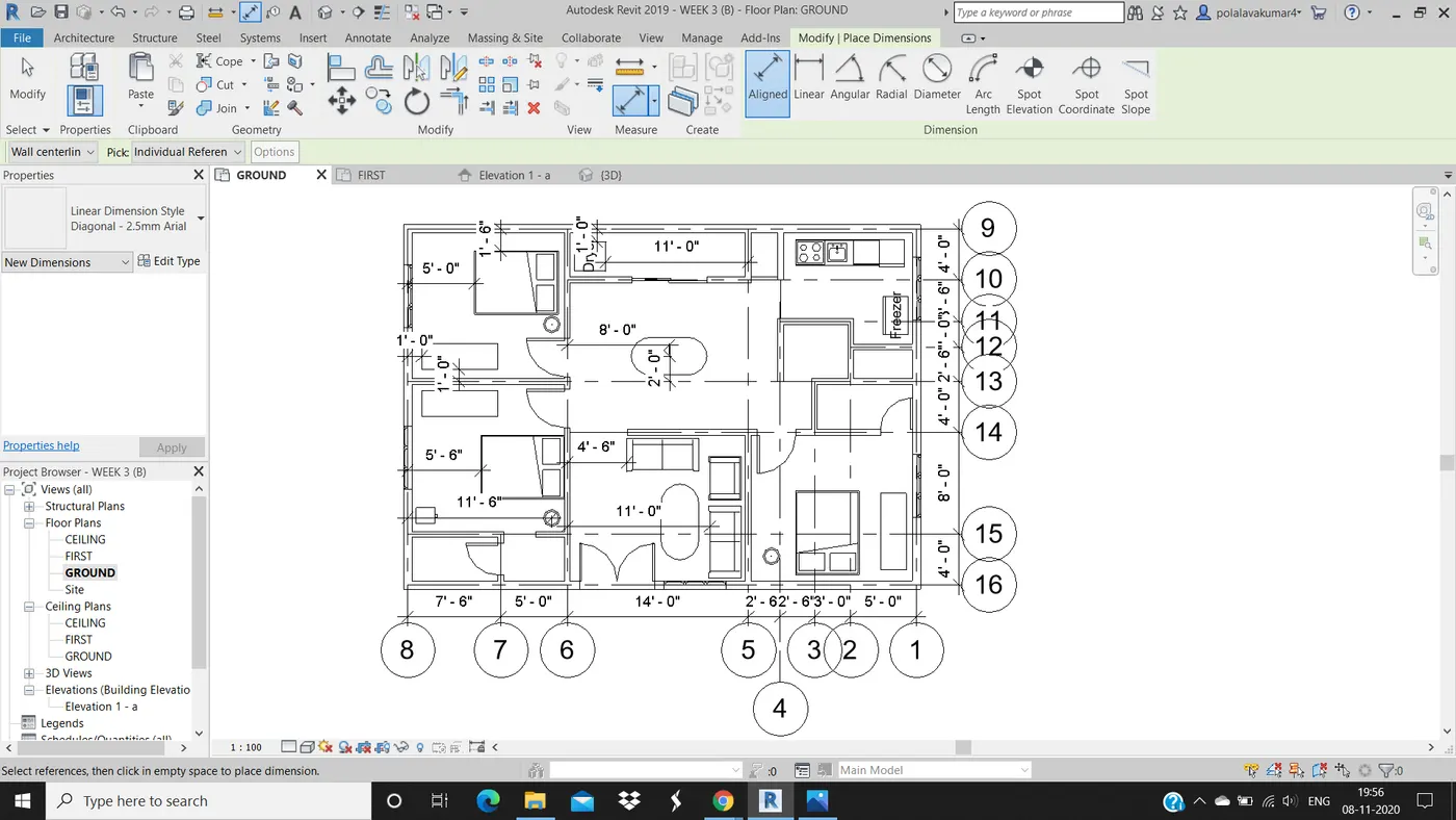
5. With the help of aligned tool from Annotate tool mark the dimensions from the components to nearby grid lines.
RESULT :
With the help of the above steps we can add grid lines to the walls and with the help of aligned tool from annotate tab we can mark the dimensions from the grid lines to the components.
QUESTION 5) Create a sheet template from the view tab and adjust the parameters on the sheet to add appropriate views.
ANS 5)
AIM : To create sheet template from the view tab and adjust the parameters on the sheet to add the appropriate views.
TOOLS USED :
- View.
- Sheet.
- A1 metric.
- Project browser.
- Parameters.
PROCEDURE :
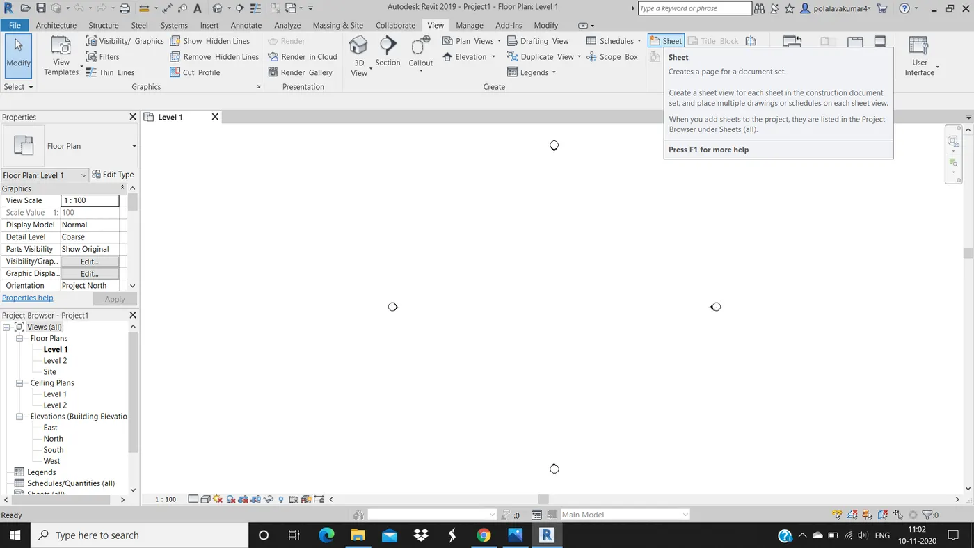
1. Go to view tab and click on sheets.
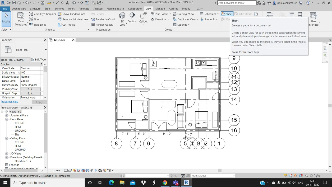
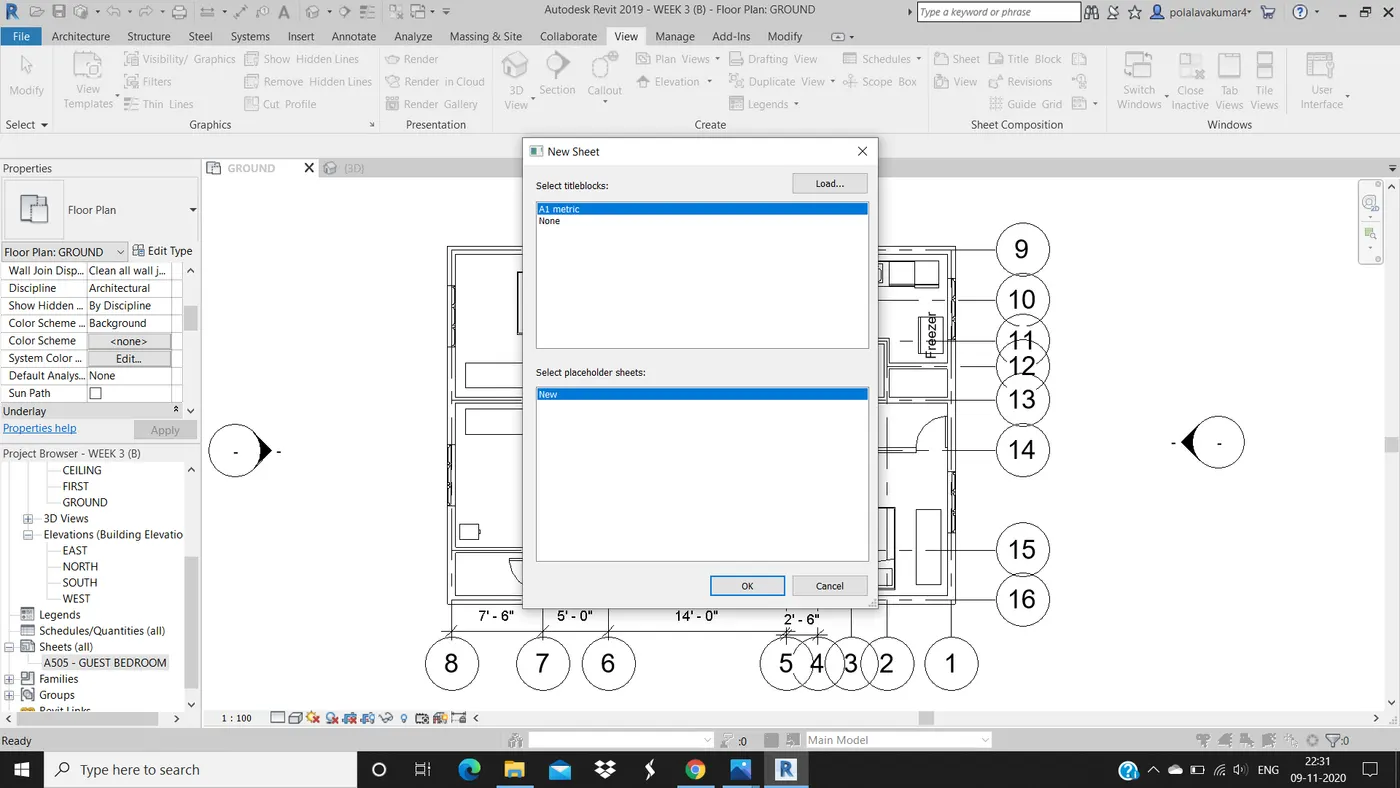
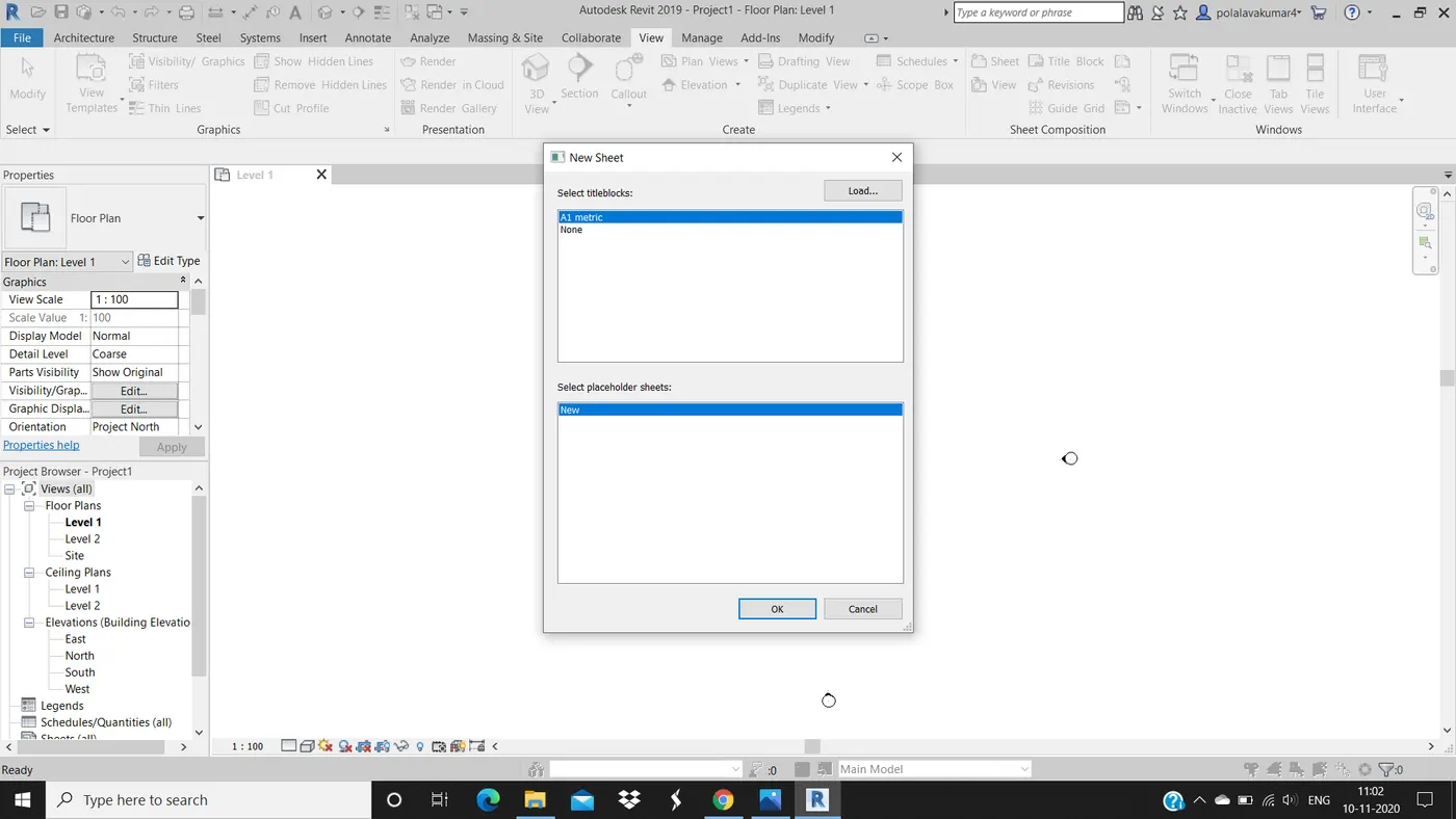
2. New sheet dialog dox opens select the type of sheet and click on ok.
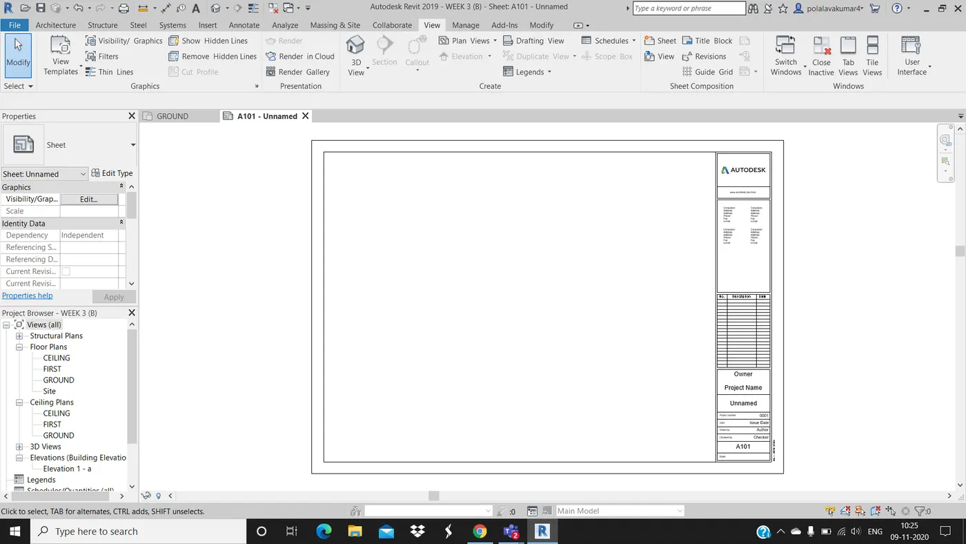
3. A default unnamed sheet appears in a new tab.
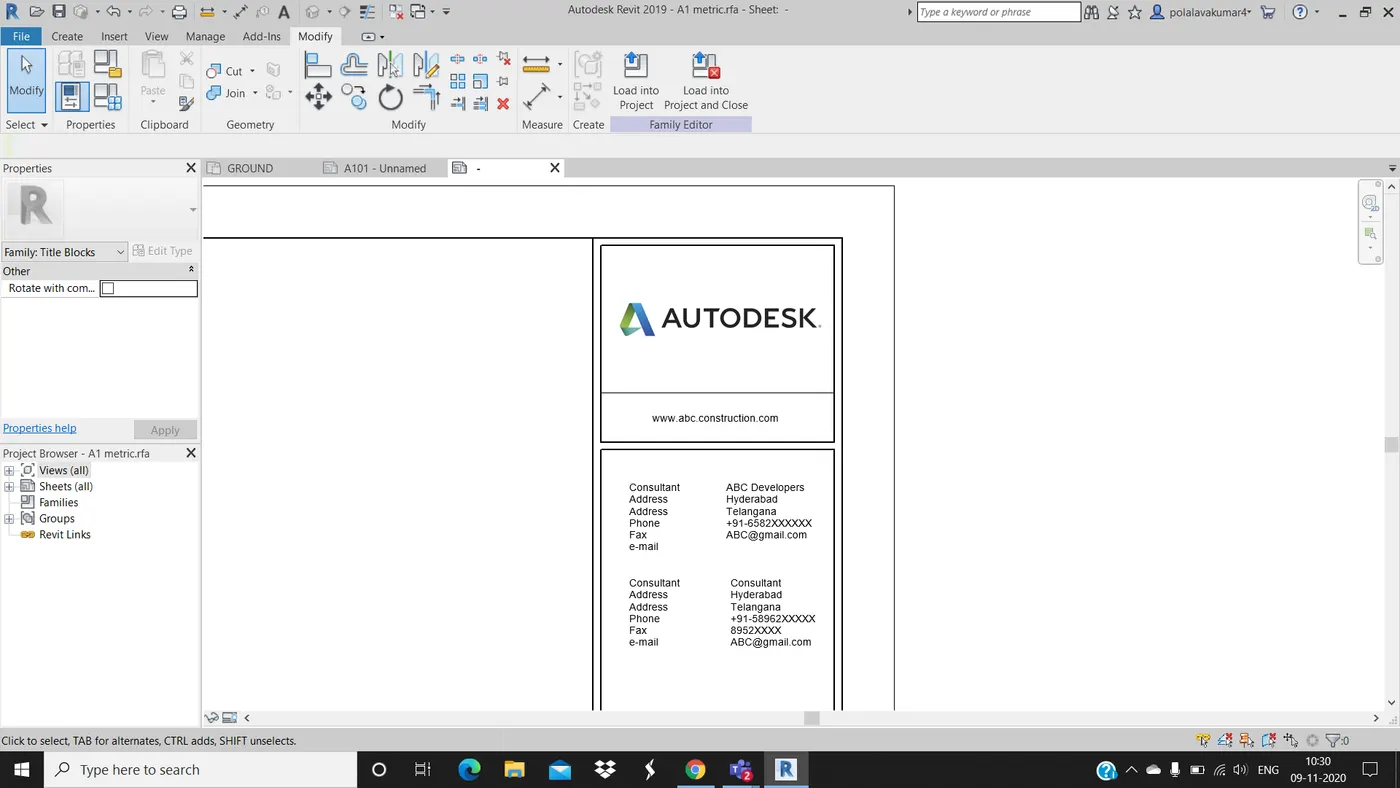
4. We can change the details on the sheet by directly clicking on the sheet or else by changing in the properties box.
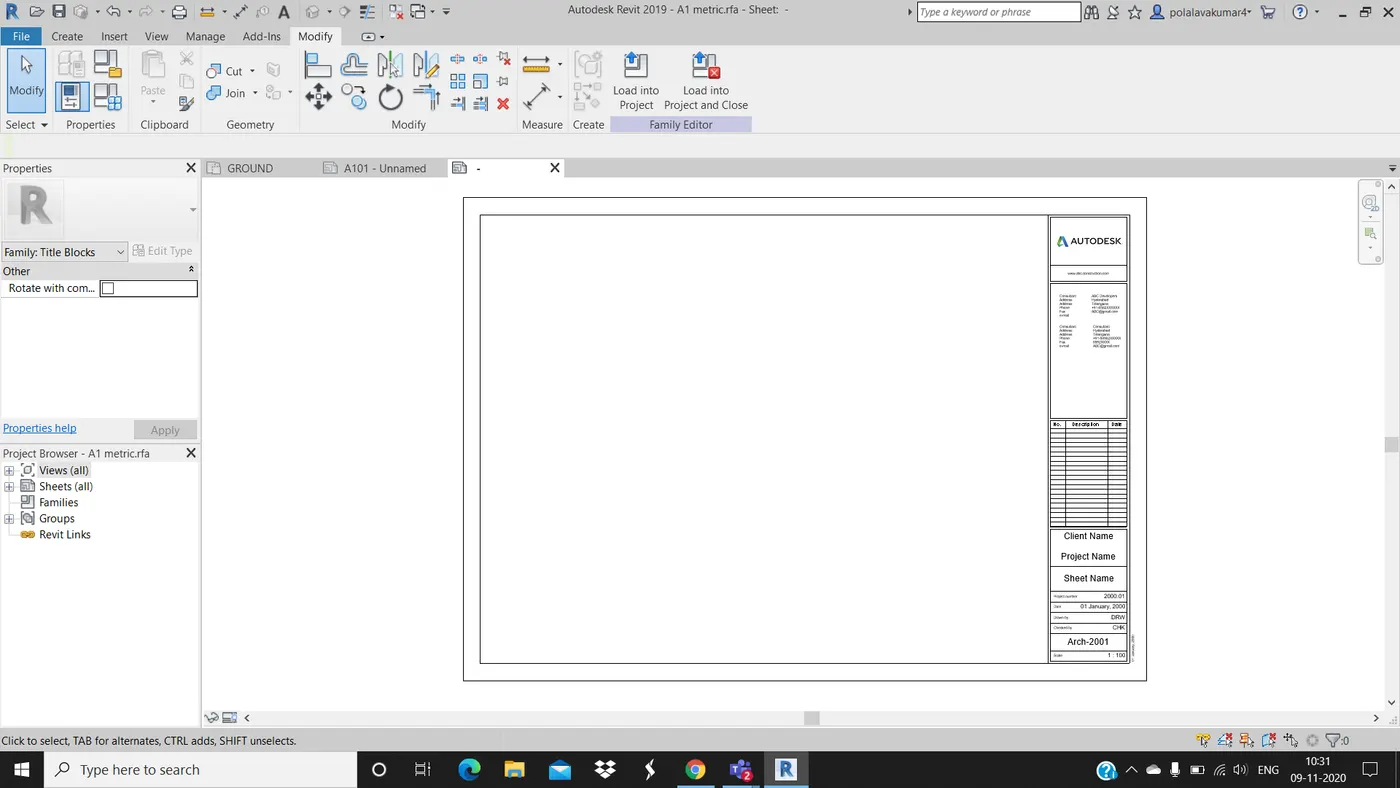
5. The new modified sheet with the required parameters is ready.
6. This modified sheet can be used for multiple purposes.
RESULT :
Thus a sheet can be created and modified from the view tab and the parameters can be adjusted.
QUESTION 6) Using the elevation tab create the elevation views, looking at your building from East, North, South and West.
ANS 6)
AIM : To create elevation views with the help of elevation tab by looking at your building from East, West, South and North.
TOOLS USED :
- View.
- Elevation.
- Property browser.
- East.
- West.
- South.
- North.
- Elevations.
PROCEDURE :
1. Open the project in which you would like to view th elevations.
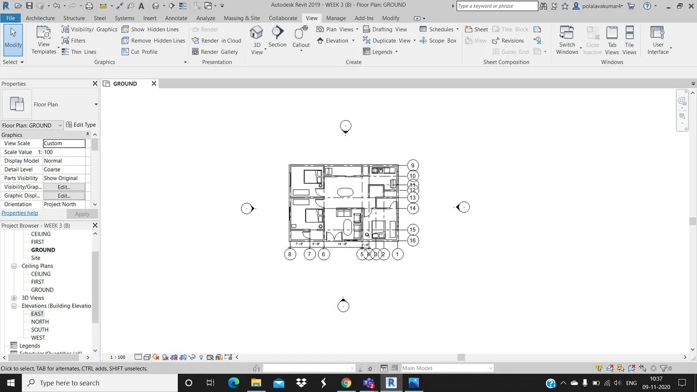
2. Select view tab and choose elevation option and place the elevation logos in all the four sides of the drawing.
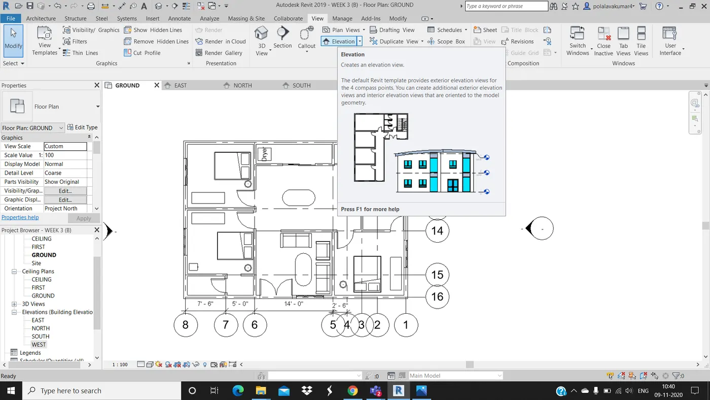
3. Click on property browser and choose elevation option.
4. Select east option to view the east elevation of the project.
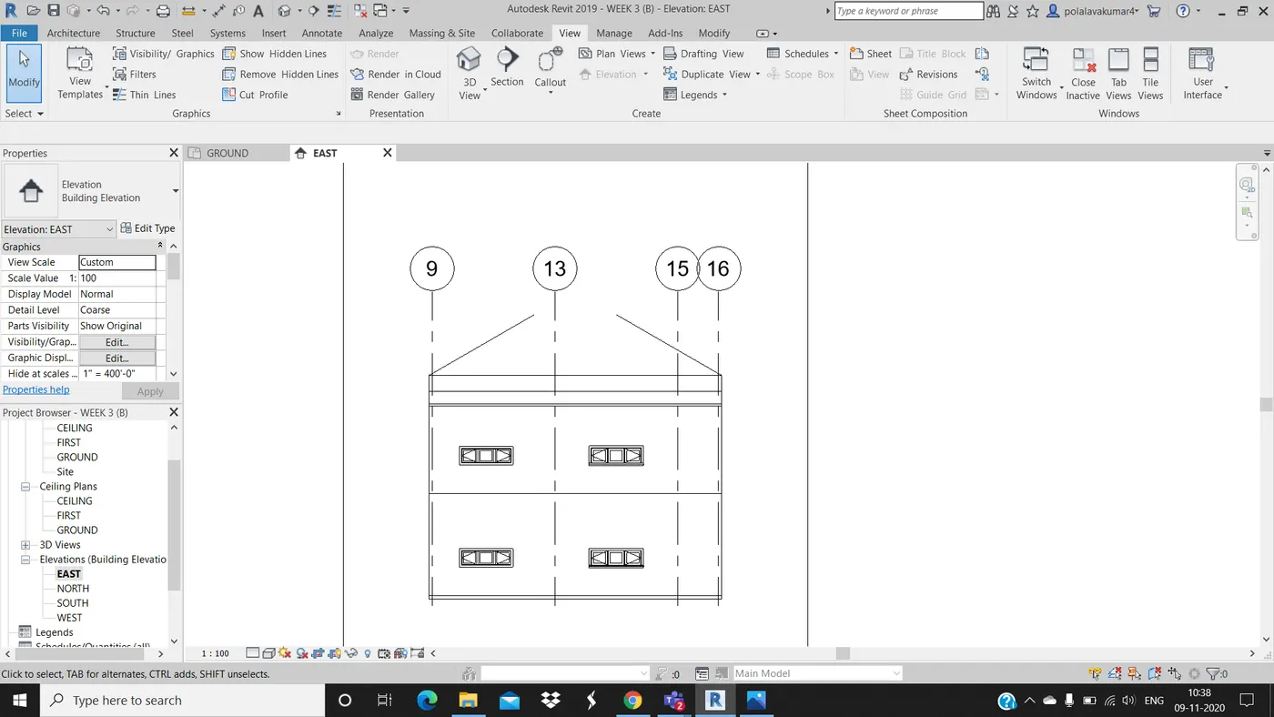
5. Select north option to view the north elevation of the project.
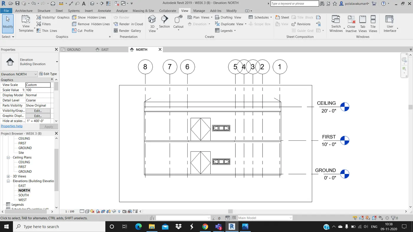
6. Select south option to view the south elevation of the project.
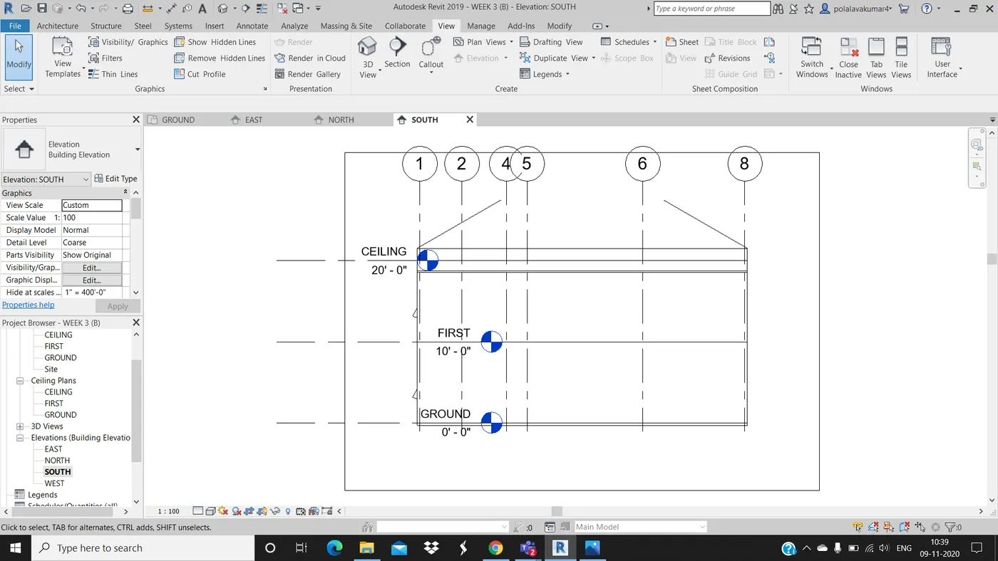
7. Select west option to view the west elevation of the project.
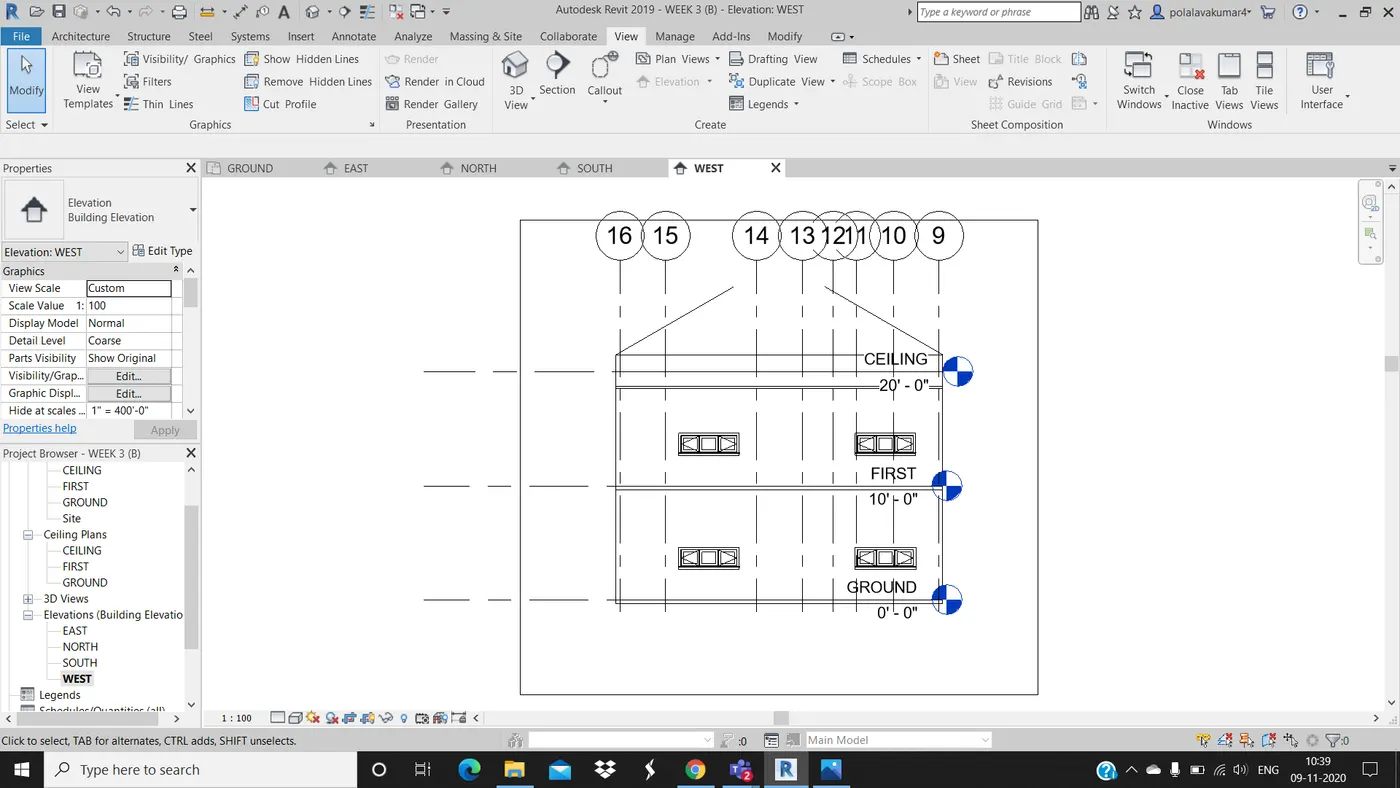
RESULT :
With the help of elevation tab we can view the object in any direction and have a detailed look of the elavations.
QUESTION 7) Produce section cut through each room either cutting across longitudinally or in a transverse direction.
ANS 7)
AIM : To produce section cut through each room either cutting across longitudinally or in transverse direction.
TOOLS USED :
- View.
- Section.
- Property browser.
PROCEDURE :
1. Open the drawing for which u want to provide the section view.
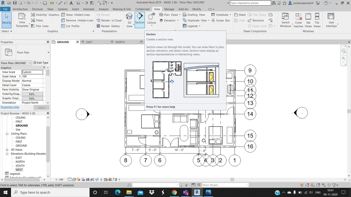
2. Go to view menu and select section option.
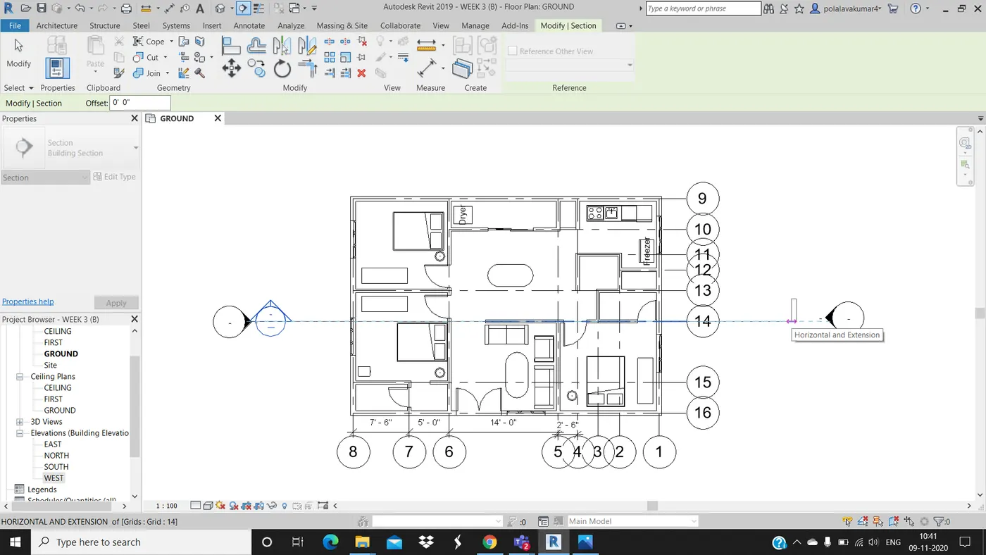
3. With the help of mouse place the cursor where you want to start the section. click on the final point where u cant the section to extend.
4. If the line is drawn horizontally we can get the transverse section of the project.
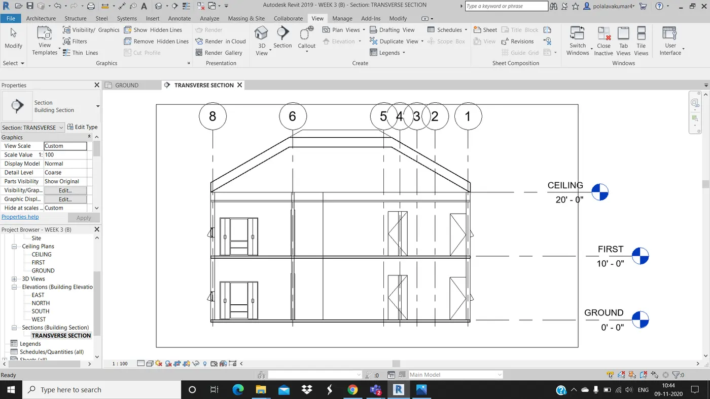
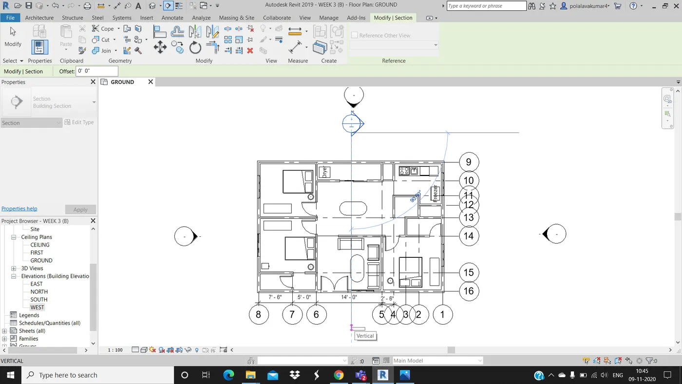
5. If the line is drawn longitudinally we can get the longitudinal section of the project.
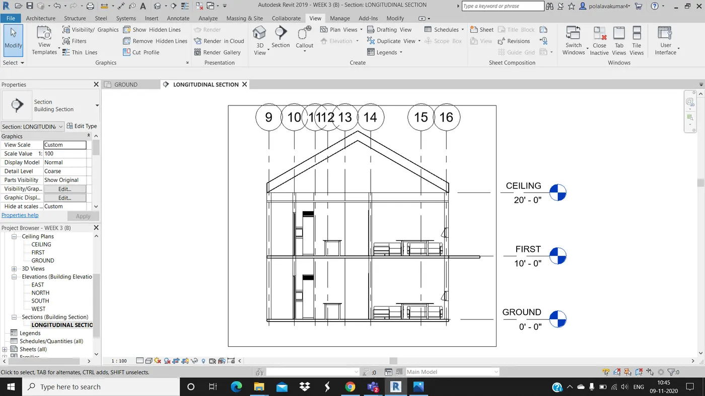
RESULT :
We can draw longitudinal sections to the project so that the project can be explained and viewed clearly.
QUESTION 8) Classify the views , Plan Views, Section Views and Elevation views to either Design or Documentation category using Properties browser.
ANS 8)
We can view an object in many views, and we can achieve to produce a model in 3D with the help of plan, elevation and sectional view.
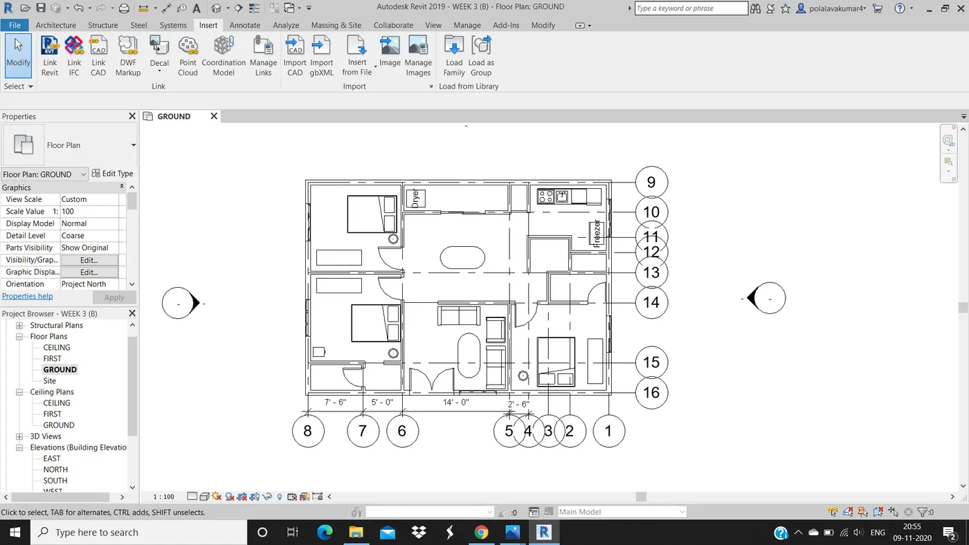
PLAN VIEW : Plan view is the view formed when the object is projected on a horizontal plane. The image of the object is formed on the X-axis. When the plan view is seen from the direction perpendicular to the vertical plane the image observed is a straight line. The plan view can only be observed when seen perpendicular to the horizontal plane.
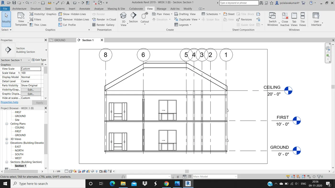
SECTION VIEW : Section view is the view which helps us to see the interior or inner part of the object. This view is mainly used to observe and analyze the interior parts. The parts which can not be explained in the normal 3D view , they can be observed more clearly in section view. With the help of the section view we can cut a part of portion for internal view.
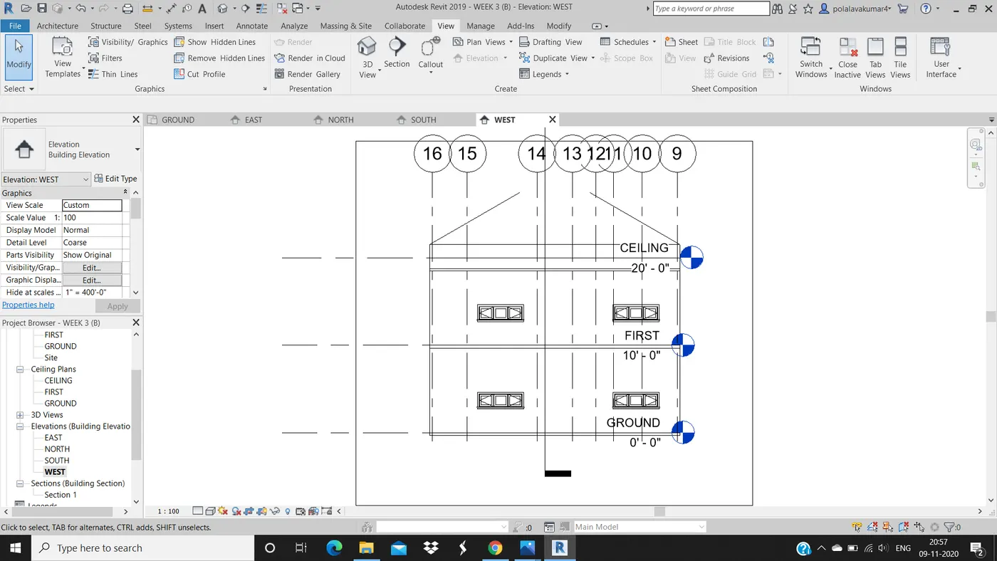
ELEVATION VIEW : Elevation is the view of a 3D object when we see the object perpendicular to the vertical plane or parallel to the horizontal plane. Elevation view can also be called as side view and the object can be viewed from all the 4 directions North, South, East and West. In the elvation view we can see the detailed view of the levels or floors.
QUESTION 9) Using the sheet template produced create multiple sheets as follows.
ANS 9)
AIM : To use the sheet template produced to crerate multiple sheets.
TOOLS USED :
- View.
- Sheet.
- Properties.
- Graphics.
- Insert.
- Image.
PROCEDURE :
1. First go to view tab and select sheet.
2. New sheet dialog box appears, select A1 metric and click on ok.
3. A new default unnamed sheet appears in the new tab.
4. We can change the parameters on the sheet by directly clicking on the sheet or we can go to properties and change the parameters.
5. Name the sheet as A101 and add the ground floor architecture plan.
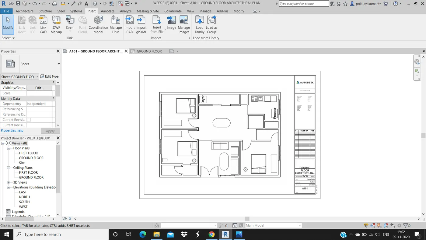
6. Name the sheet as A102 and add the first floor architecture plan.
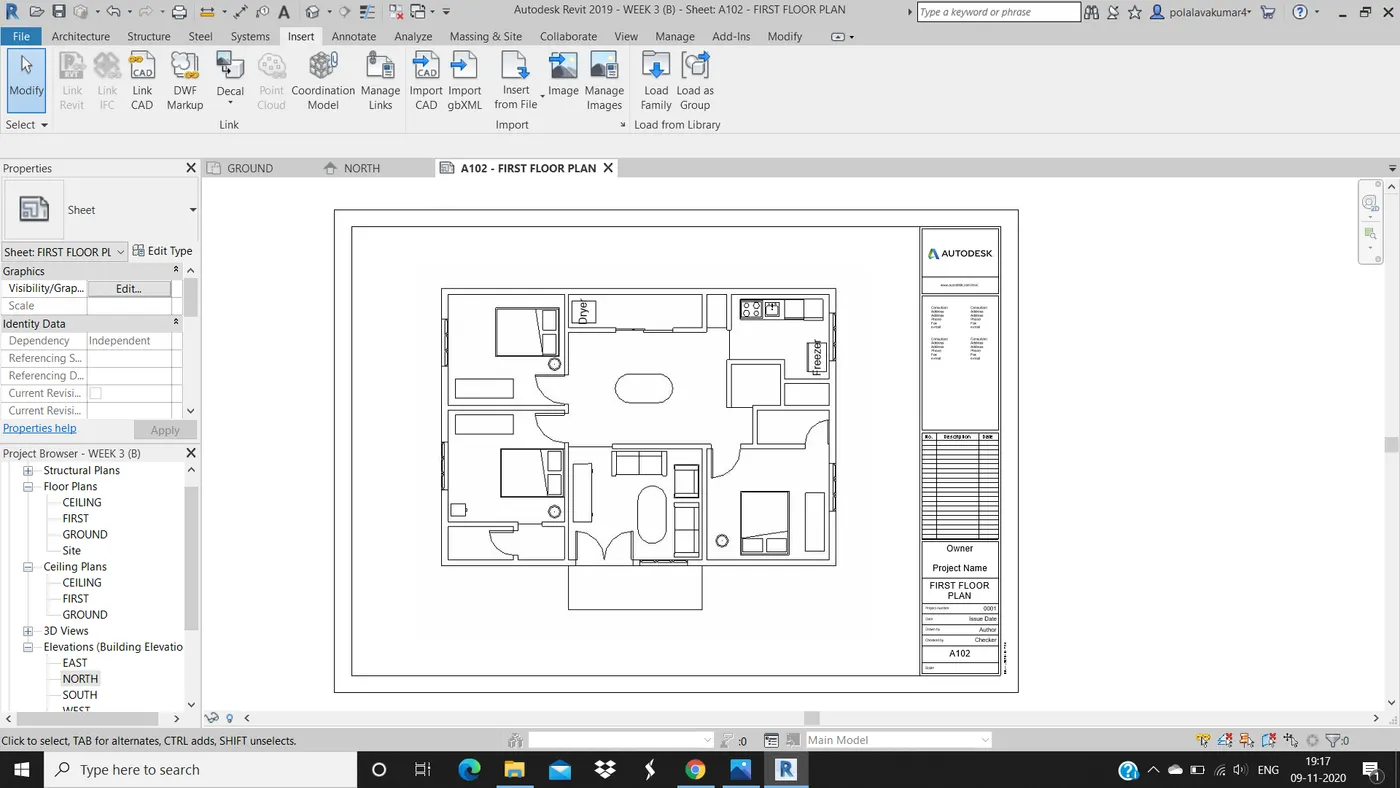
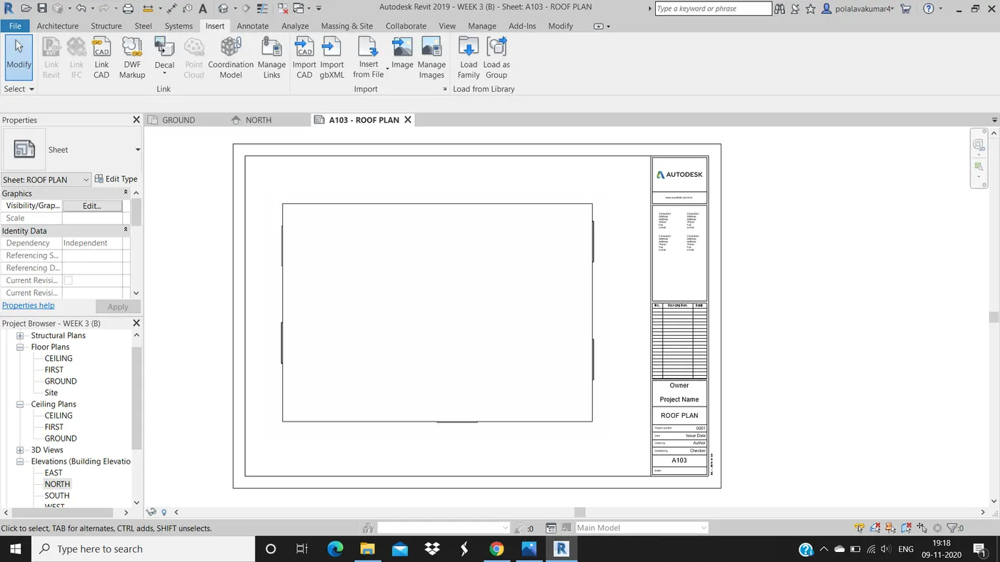
7. Name the sheet as A103 and add the roof plan.
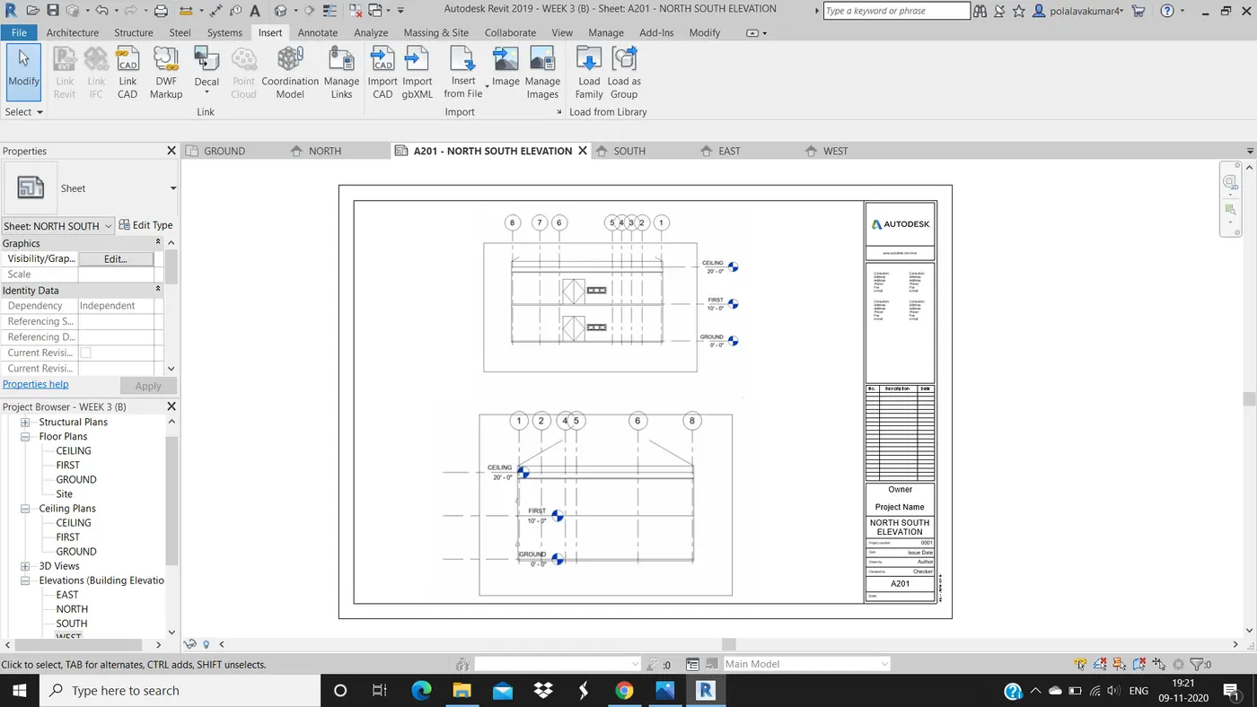
8. Name the sheet as A201 and add the North-South elevation plan.
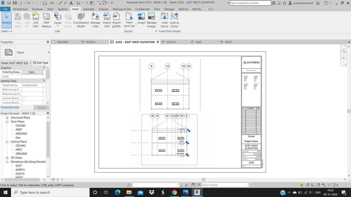
9. Name the sheet as A202 and add the East-West elevation plan.
RESULT :
With the help of sheet template we can add multi sheets for separate plan views with correct parameters.
QUESTION 10) Create a camera specific view or a 3D view in each room ( living, dining, bed room ) . Based on the views create new shet of sheets starting A-501 (you can add as many sheets after , 502, 503.. n)to place the 3D view images.Produce the sheets as a part of project drafting.
ANS 10)
AIM : To create a camera 3D view in each rooms and create new sheets to add the 3D images. Name the sheets as A501, A502,......and so on.
TOOLS USED :
- View.
- 3D view.
- camera.
- sheet.
- Properties.
- Graphics.
PROCEDURE :
1. Open the project and go to view tab and select 3D view.
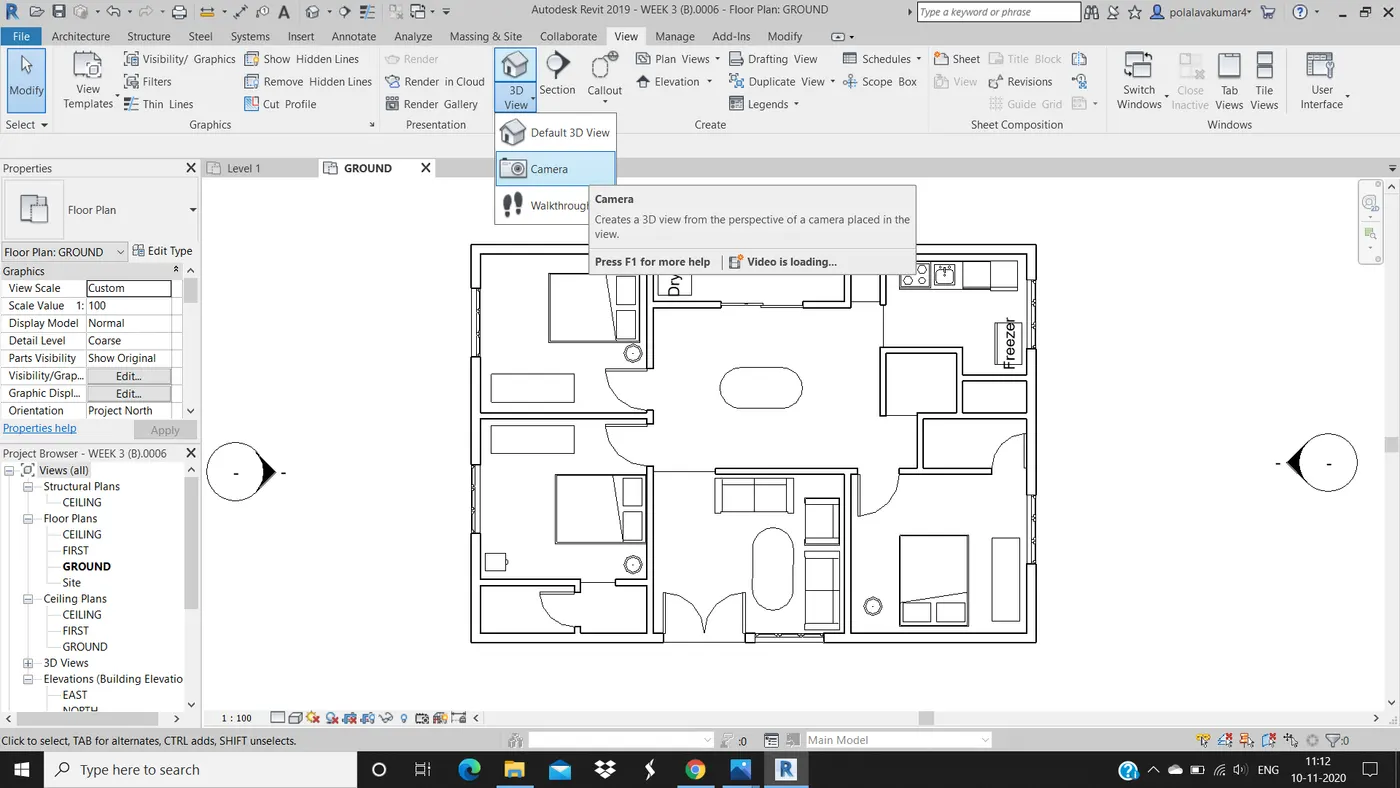
2. Under 3D view selectg camera view.
3. With the help of camera view place the camera on the plan and tap at the point where you want to extend the view.
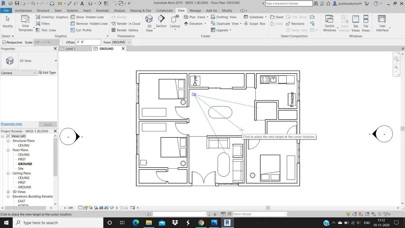
4. Then go to view tab and select sheets.
5. A new default unnamed sheet appears in the new tab.
6. We can change the parameters on the sheet by directly clicking on the sheet or we can go to properties and change the parameters.
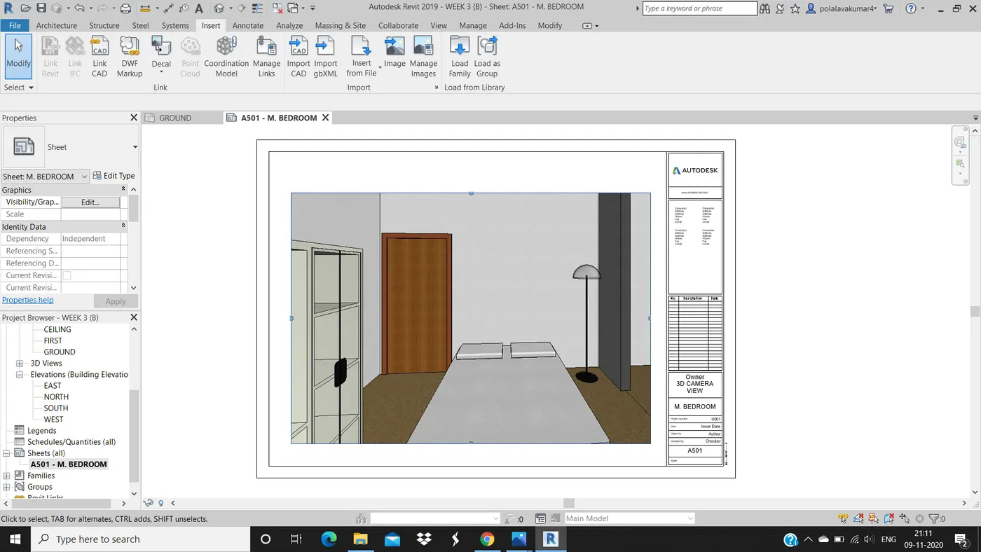
7. Name the sheet as A501 and add the 3D camera view images of master bedroom.
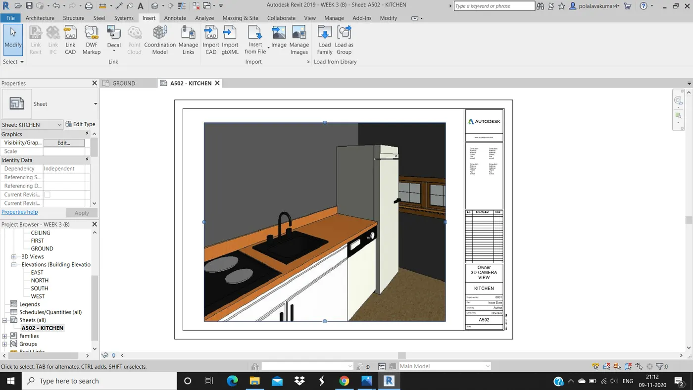
8. Name the sheet as A502 and add the 3D camera view images of kitchen.
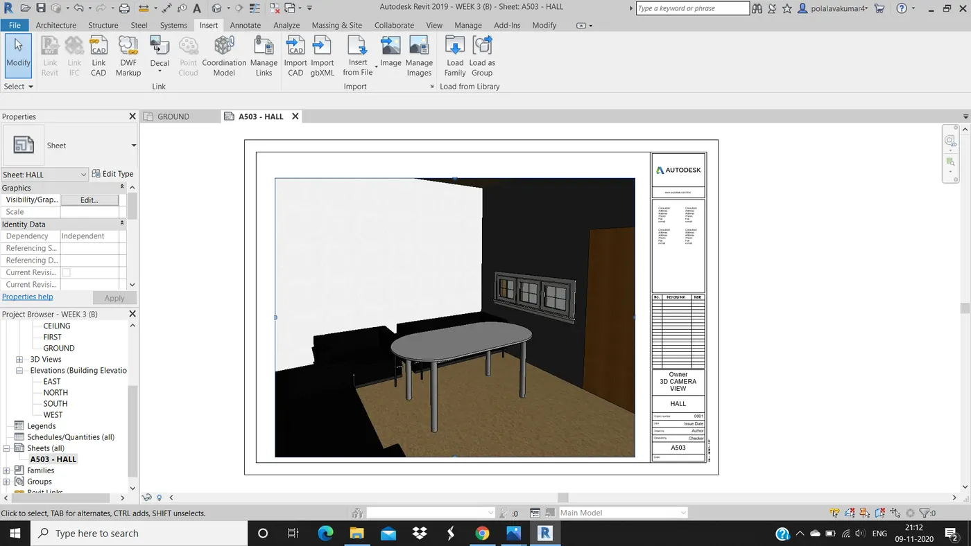
9. Name the sheet as A503 and add the 3D camera view images of hall.
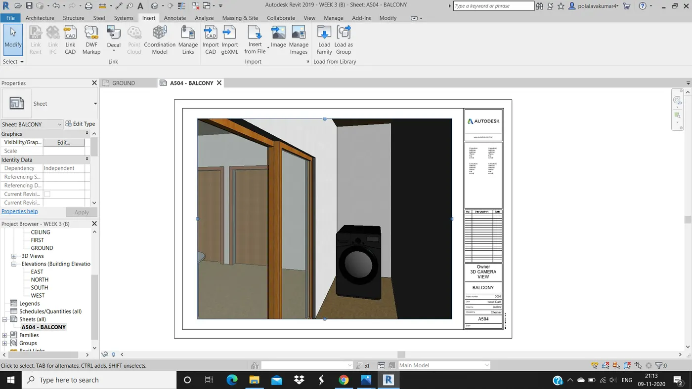
10. Name the sheet as A504 and add the 3D camera view images of balcony.
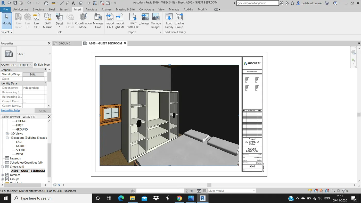
11. Name the sheet as A505 and add the 3D camera view images of guest bedroom.
RESULT :
We have created camera 3D views for different views in the project and added them into sheets naming them as A501, A502,.....and so on up to A505.