REVIT_Introduction to REVIT_Week 1
ANS 1)
AIM:
To form a file menu, create a new project and name the project appropriately.
TOOLS USED:
- Revit software.
- file
- new
- project
PROCEDURE :
- First open revit 2019 software.
- Then click on file menu and drop down box appears.
- Then click on new option and select project option under create a revit file.
- New project dialog box appears.
- Select architectural template.
- click on ok.
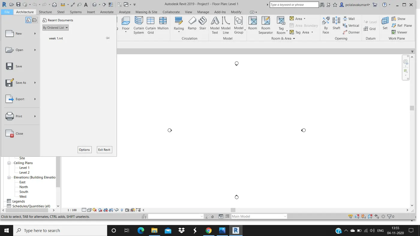
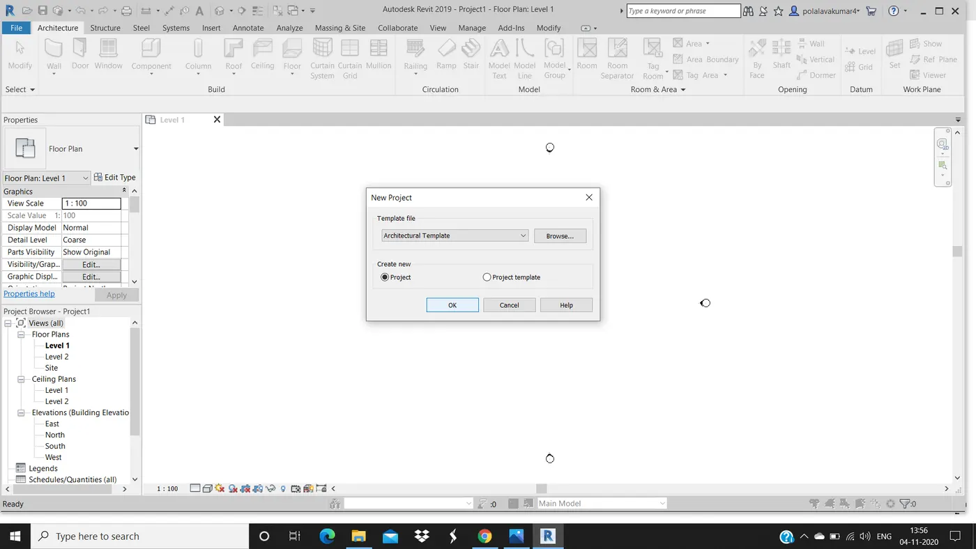
RESULT: By following the above steps we have formed a file menu and created a new project whith the required template.
ANS 2)
AIM:
To save new project file and close and open using icons from the file toolbar.
TOOLS USED:
- file
- save as
- open
PROCEDURE:
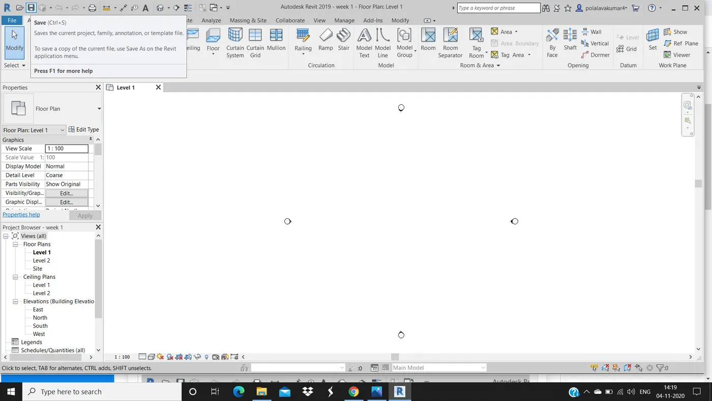
Step 1. To save a project file.
- Select save icon from the file toolbar. (or)
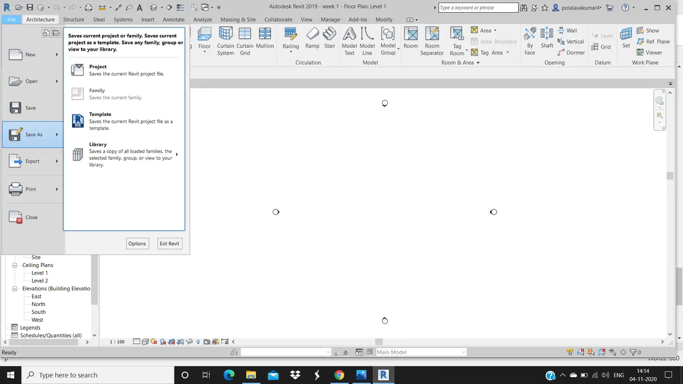
- Click on save as option from file menu.
- Select project option.
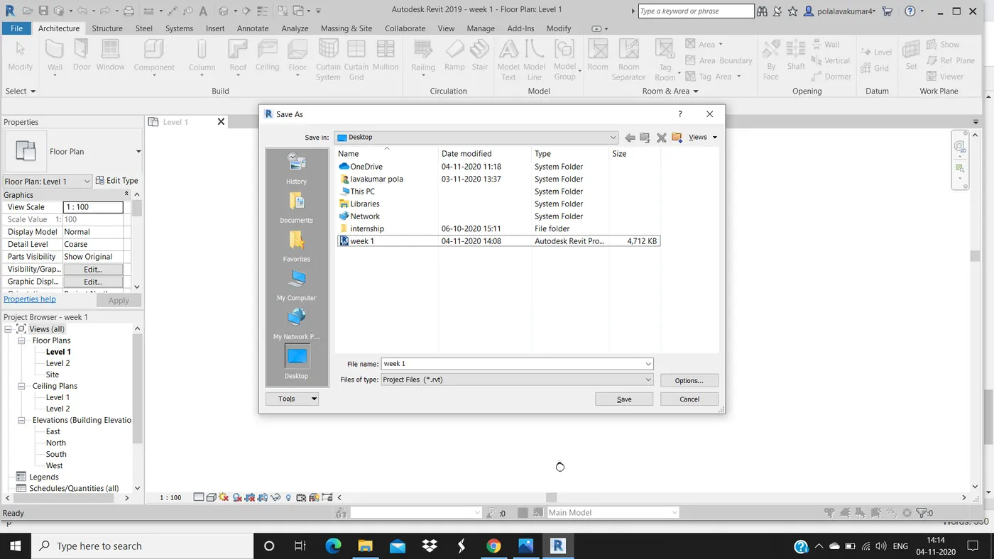
- Save as dialog box appears
- Give a name to your project say week 1.
- Select the location where you want to save the file and click on ok.
Step 2. To open and close a file.
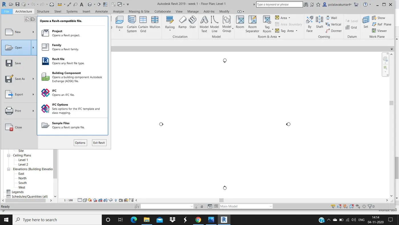
- Select the open icon on the file toolbar. (or)
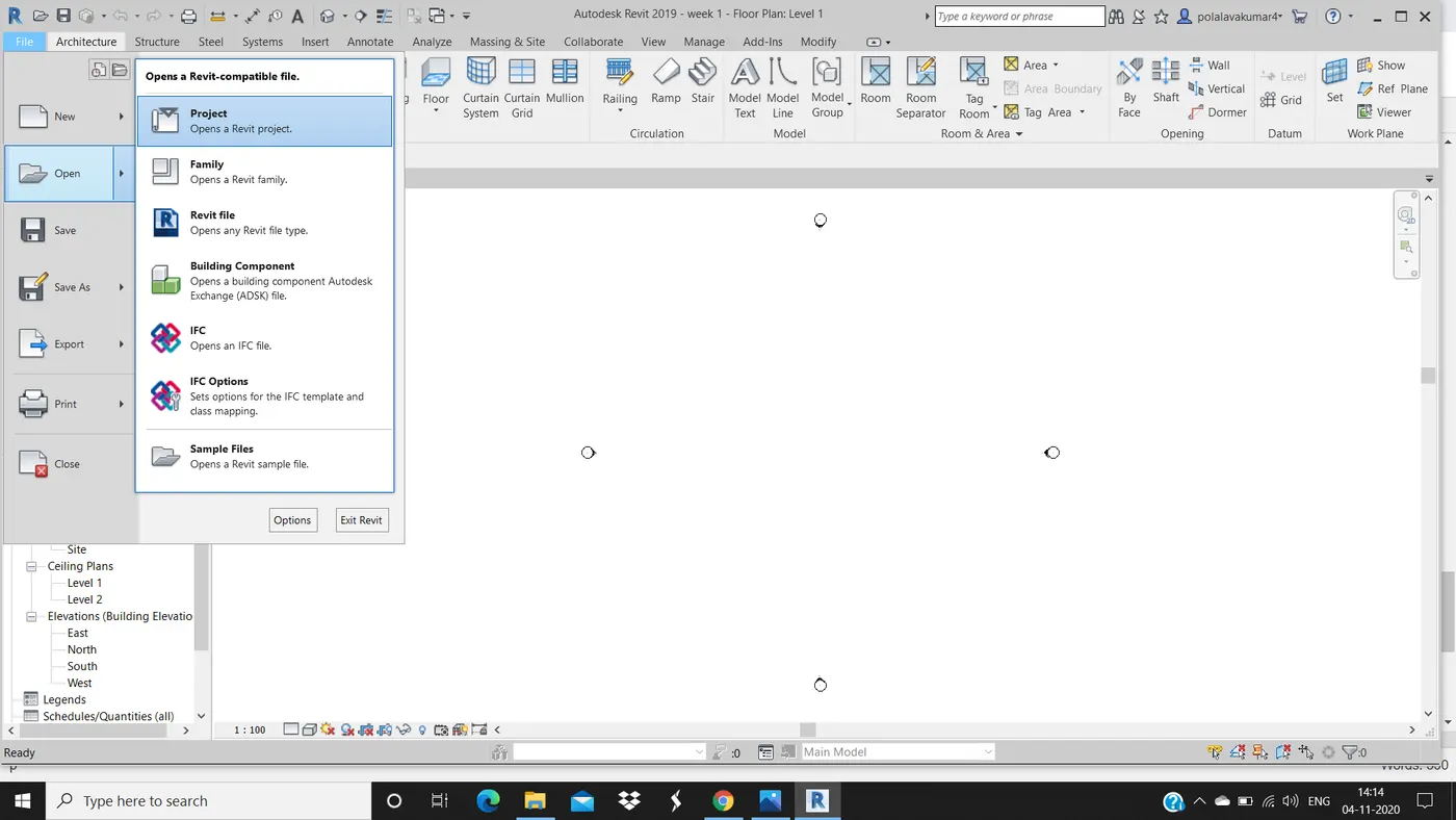
- Click on file menu and select open option.
- Click on project option.
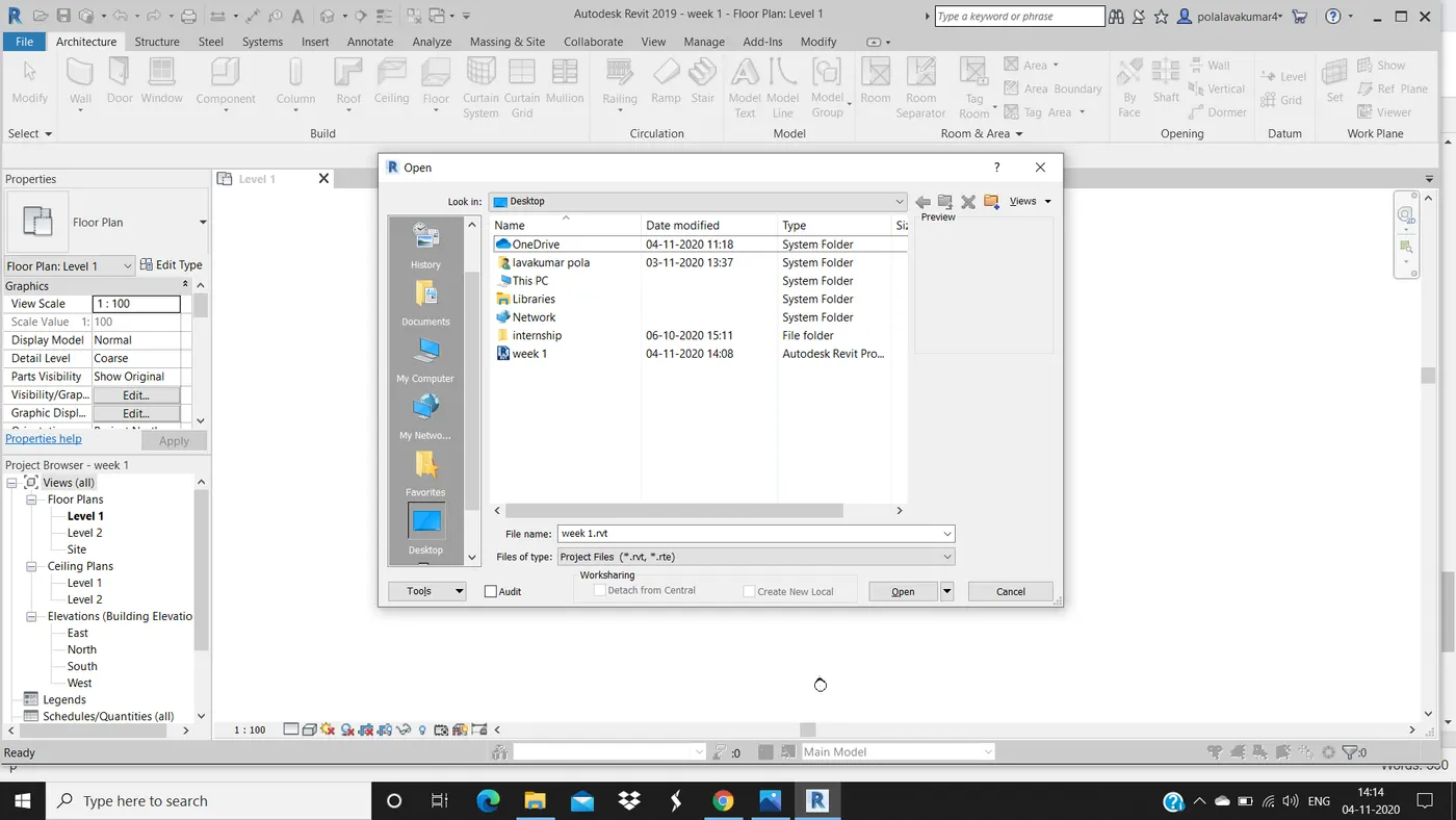
- Open dialog box appears.
- Search for the file by entering the file name in the search box or select the file.
- click on ok.
RESULT:
By following the above steps we can save, open and close a file using the file menu.
ANS 3)
AIM:
To draw a rectangular wall with the dimensions 40'-0" X 35'-0".
TOOLS USED:
- architecture.
- wall.
PROCEDURE:
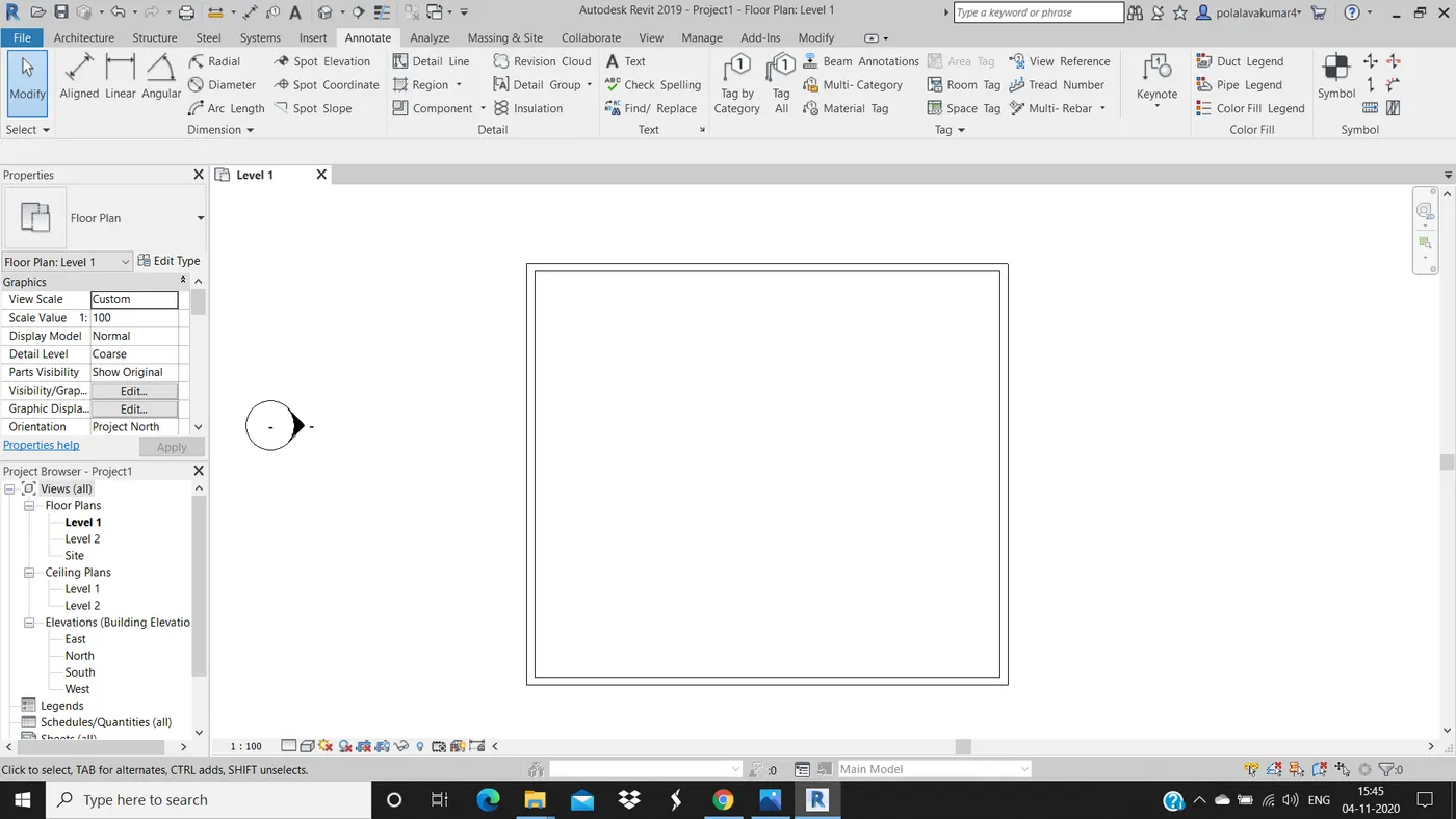
- Click on architectural toolbar and select wall tool.
- Click the cursor on the drawing area and draw a horizontal line of length 40'.
- Repeat the same process and draw the vertical sides of the walls with a dimension of 35'.
RESULT:
We have obtained a rectangular wall with deminsion of 40' x 35' by following the above steps.
ANS 4)
AIM:
To add dimensions to the layout with the help of aligned tool from the annotate tool bar.
TOOLS USED:
- Annotate.
- Aligned.
PROCEDURE:
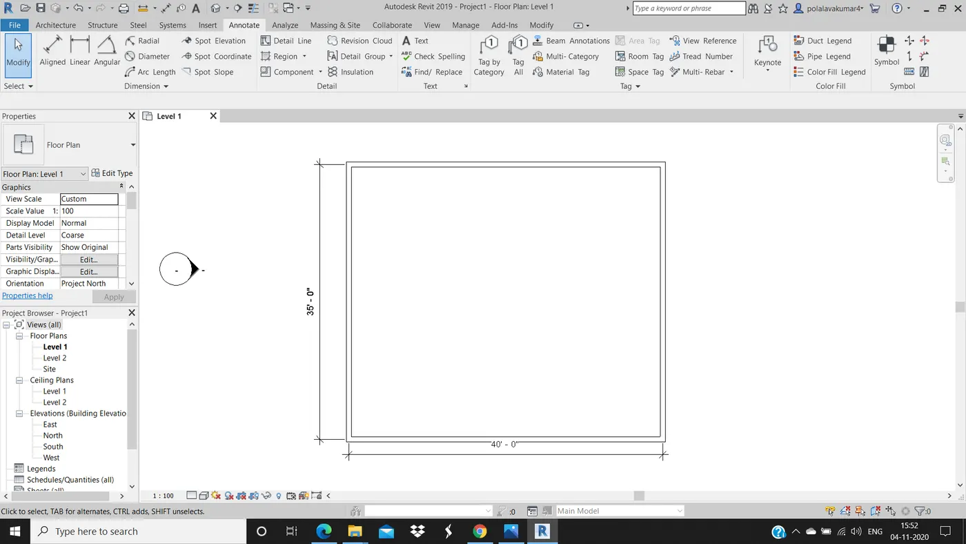
- Click on annotate on the ribbon.
- Select aligned optioin.
- Click on the starting and ending points of the wall.
- Drag the dimension of the wall to the required place.
RESULT:
With the help of the above following steps we have added dimention to the project.
ANS 5)
AIM:
To use the properties browser to switch to different wall types.
TOOLS USED:
- Properties.
- Wall type.
PROCEDURE:
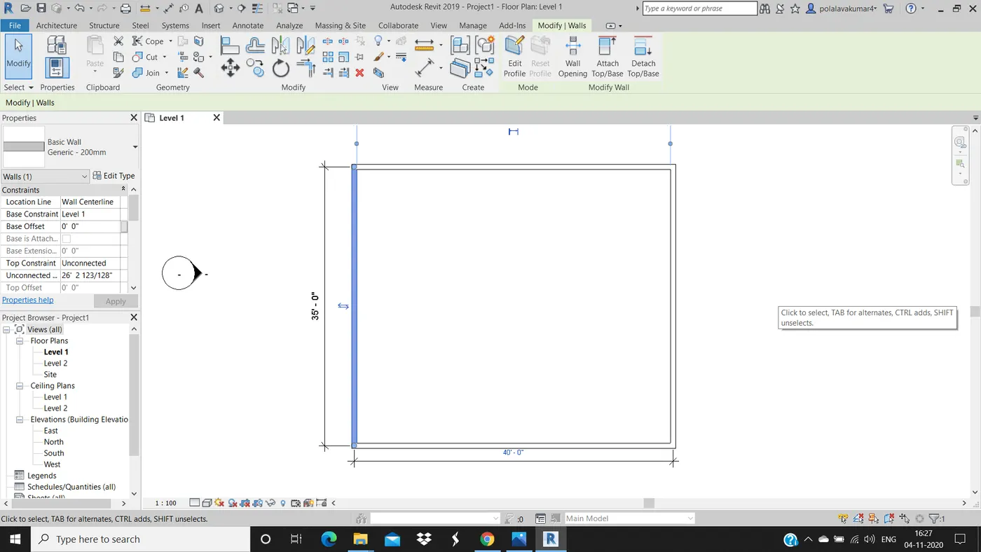
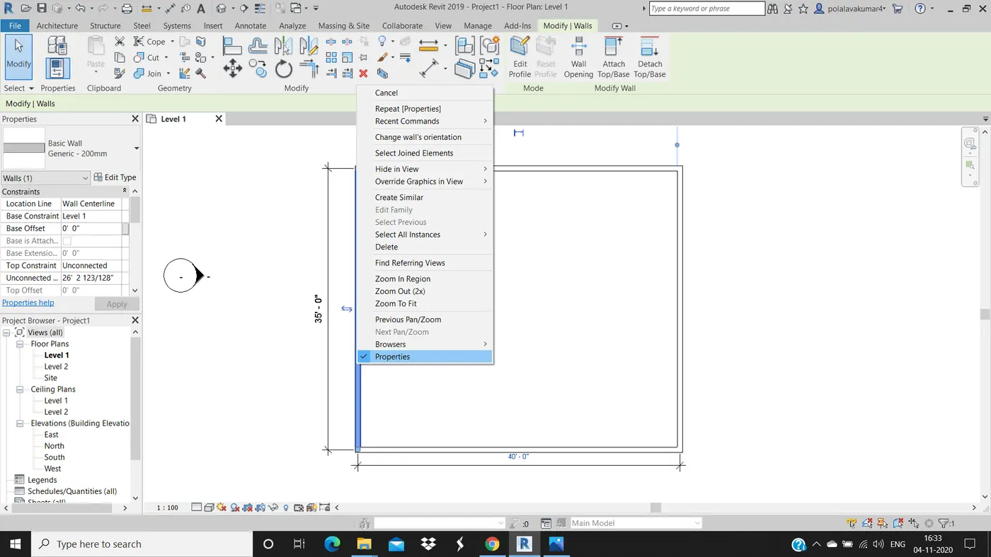
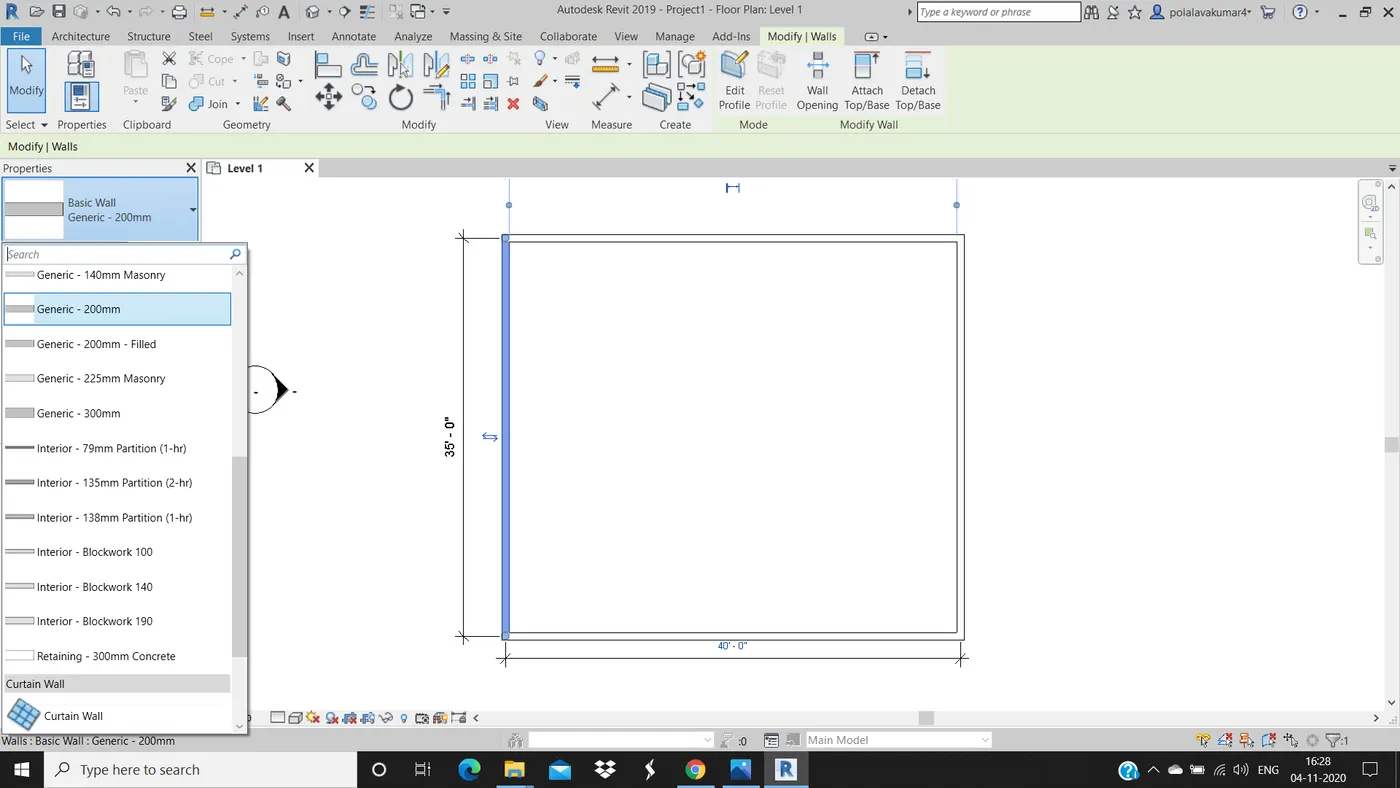
- Select the wall and right click.
- Select properties from the drop down box.
- Click on the properties and select the wall type to which you want to change.
RESULT:
With the help of the above steps we can switch to different wall types using properties browser.
ANS 6)
AIM:
To create a 3D view with the help of view tool bar and save the view with appropriate name.
TOOLS USED:
- View.
- 3D view.
PROCEDURE:
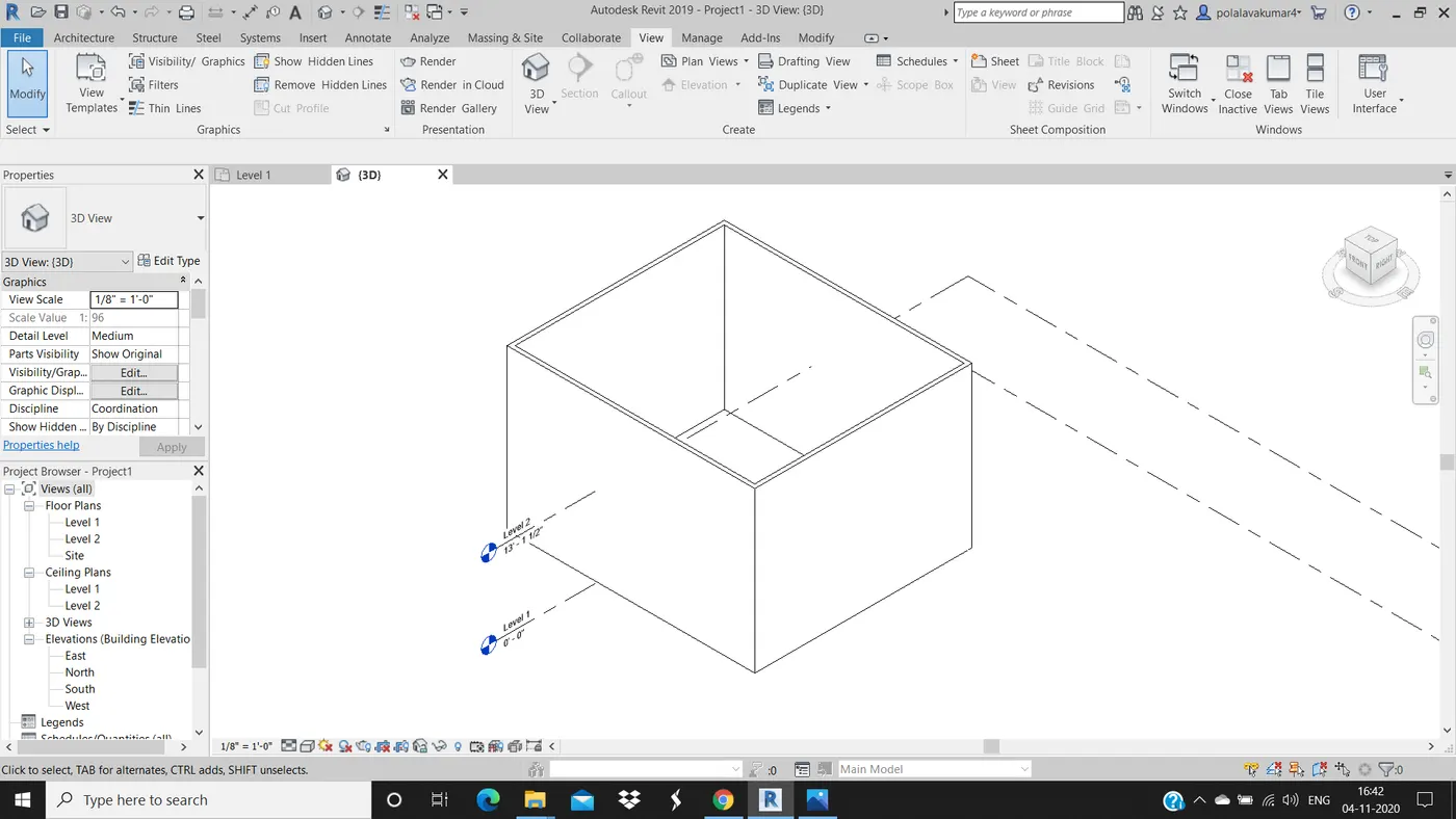
- Click on view on the ribbon.
- Next click on 3D view.
- Then the project gets converted into 3D view.
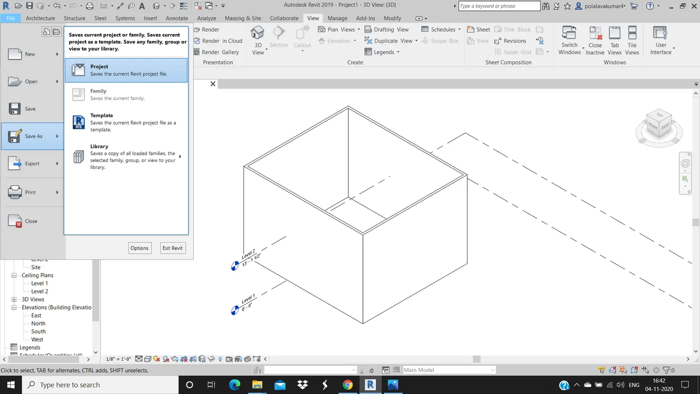
- Click on file menu.
- Select save as option and click on project.
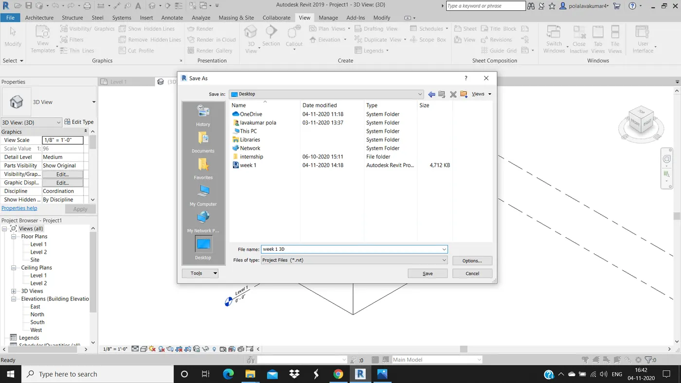
- Save as dialog box opens.
- Give a appropiate name say weel 1 3D.
RESULT:
With the above steps we are successful in creating a 3D view of the project and saving with a appropriate name.
ANS 7)
AIM:
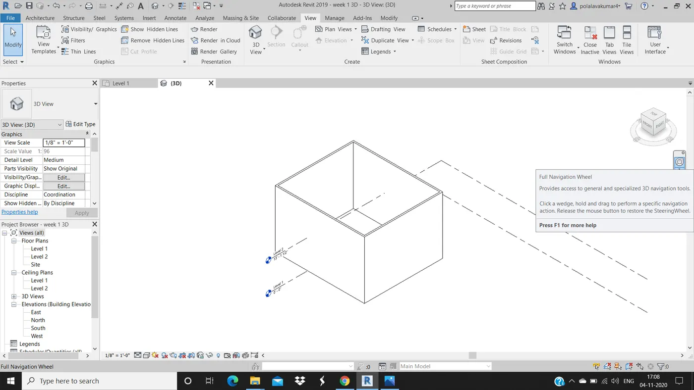
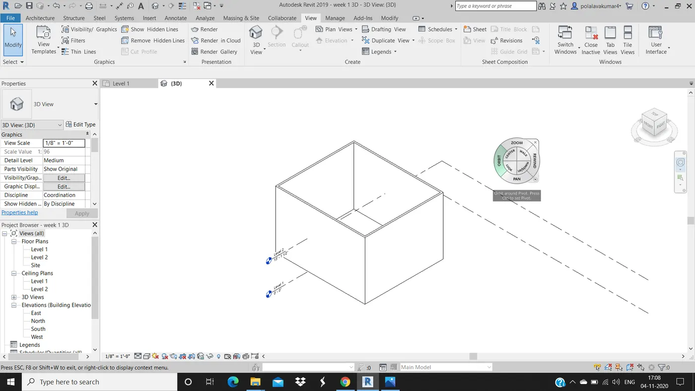
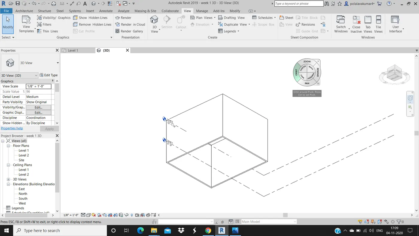
Navigate through the 3D model using view cube. Orbit/pan through the model layout created.
TOOLS USED:
- Full navigation wheel.
- Orbit.
- Pan.
PROCEDURE:
- First convert the 2D view project to 3D view.
- Next click on the full navigation tool which is located to the rightmost side.
- There we can select orbit and pan opitons by clicking on the orbit/pan option on the navigation tool.
RESULT:
We can successfully navigate through the 3D model using the view cube. We can also orbit/pan through the model layout created.
ANS 8)
AIM:
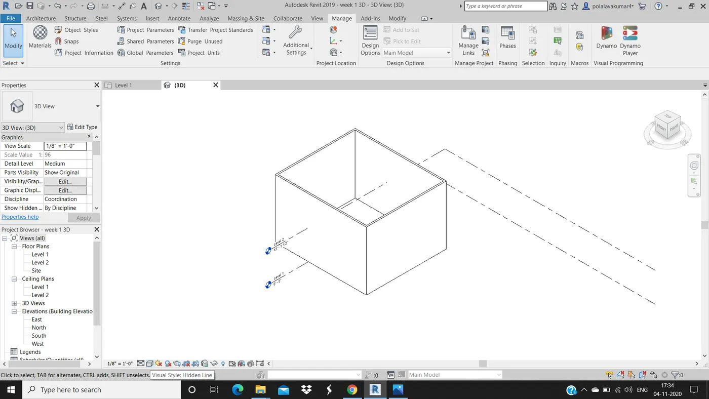
Use the visibility settings option below to switch model to shaded, realistic, hidden lines options.
TOOLS USED:
- Visual style.
- Shaded.
- Realistic.
- Hidden lines.
PROCEDURE:
- Click on the Visual style option which is present at the bottom of the screen.
- Select shaded option in the visual style drop up box.
- Select realistic option in the visual style drop up box.
- Select hidden lines option in the visual style drop up box.
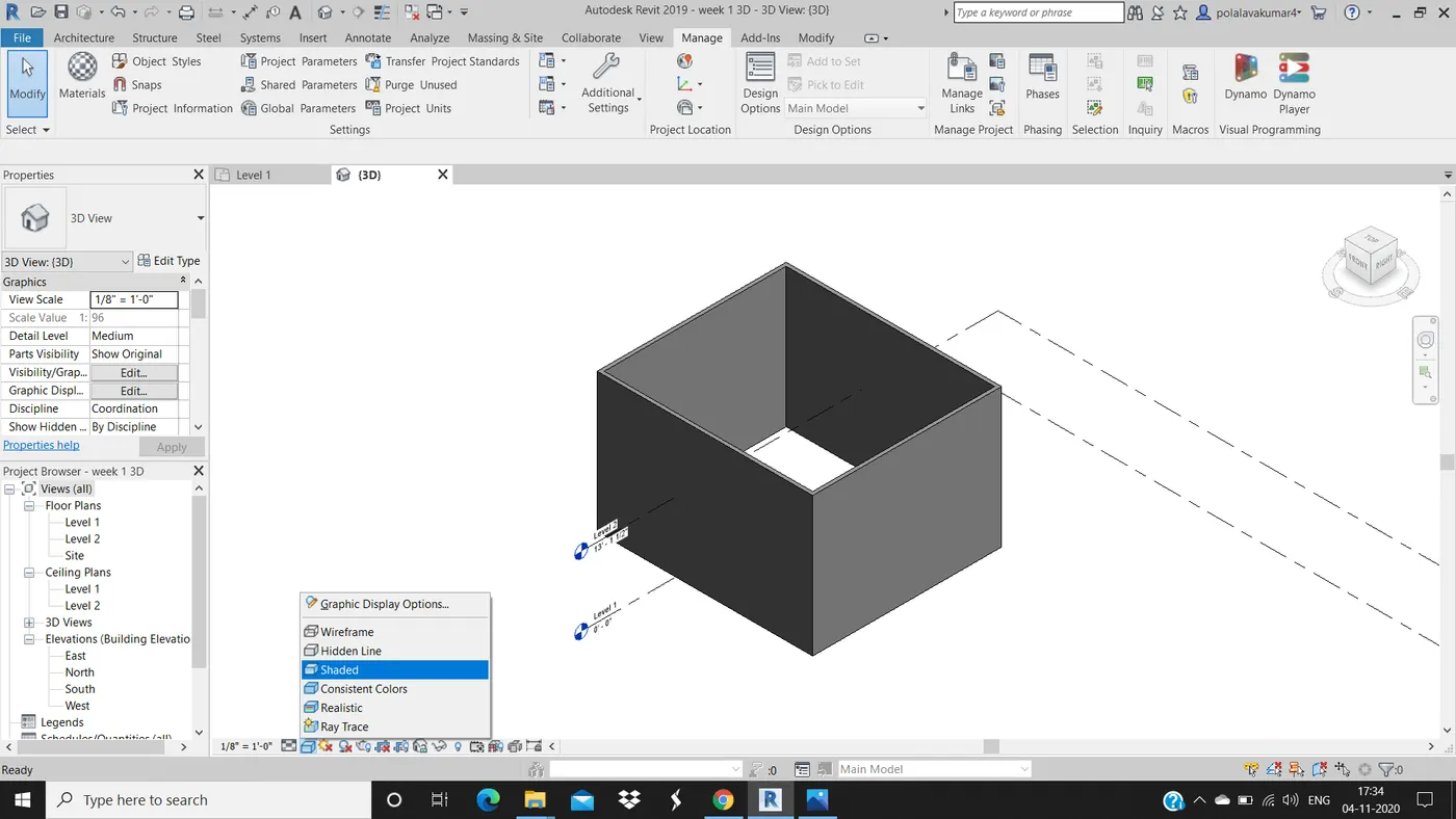
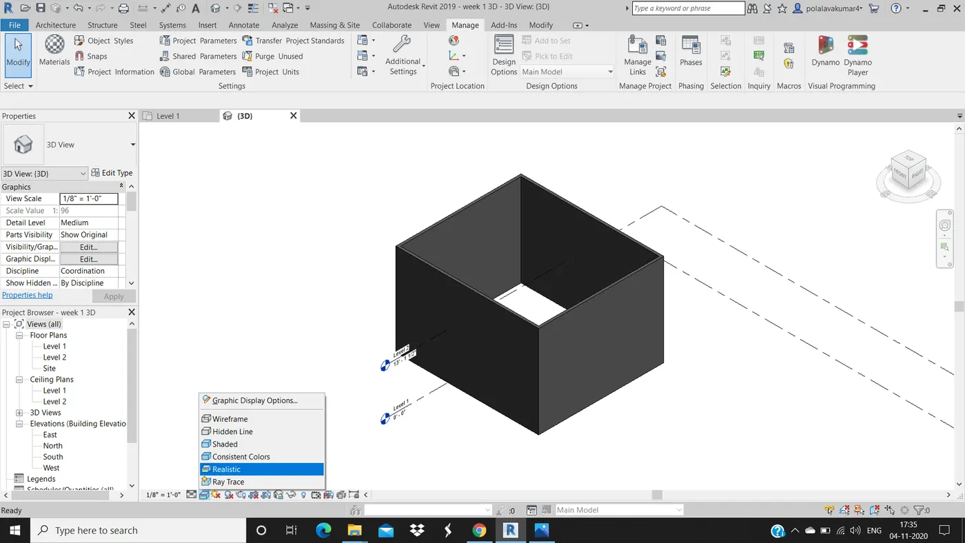
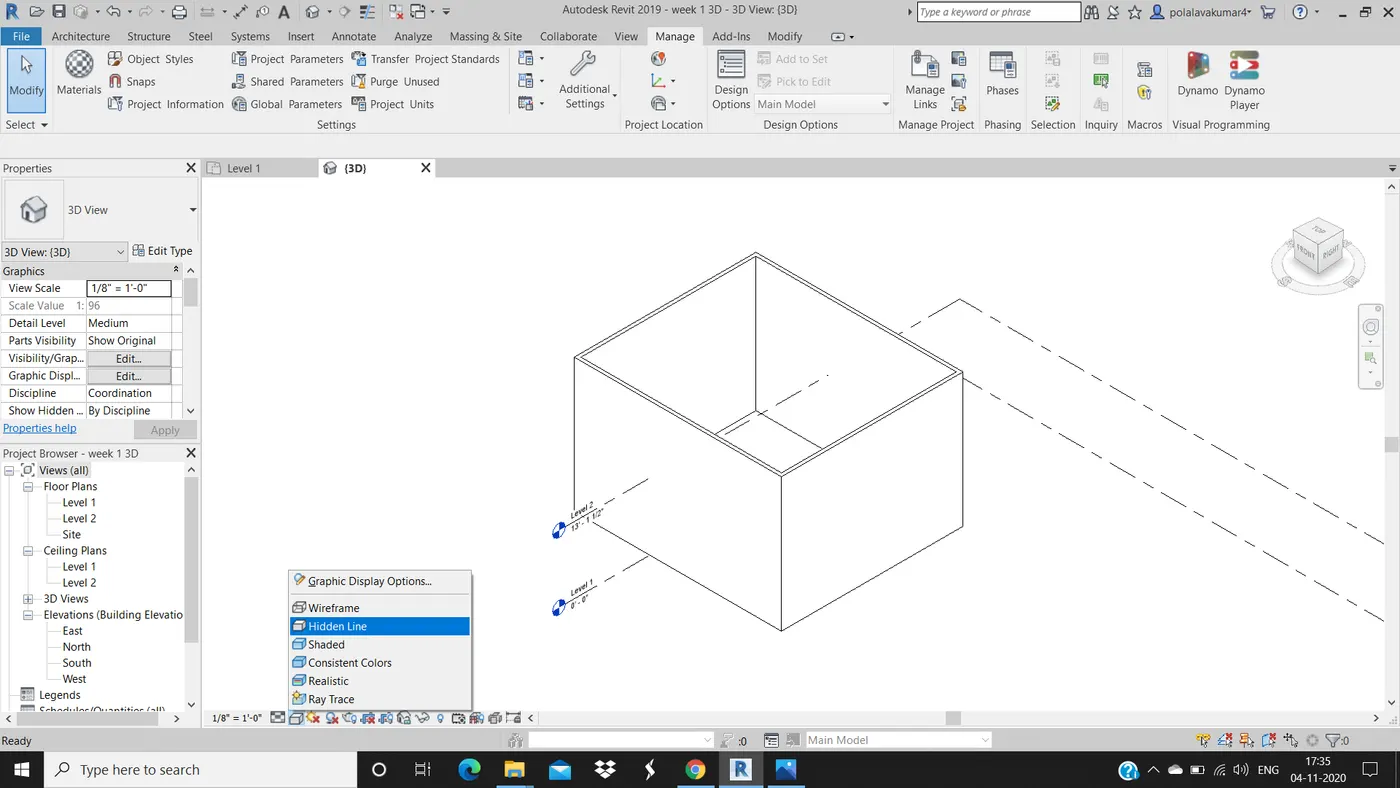
RESULT:
With the help of visibility settings option we can switch the model into shaded, realistic and hidden lines options.
ANS 9)
AIM:
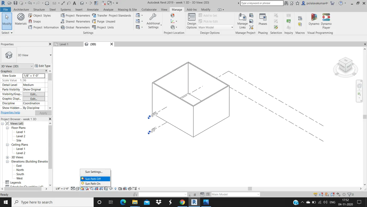
To turn the sunlight on and off to view shadings in the layout created.
TOOLS USED:
- Sun path on.
- Sun path off.
PROCEDURE:
- Click on the sun path option which is located at the bottom.
- Click on "sun path on" to turn on sun path.
- Click on "sun path off" to turn off sun path.
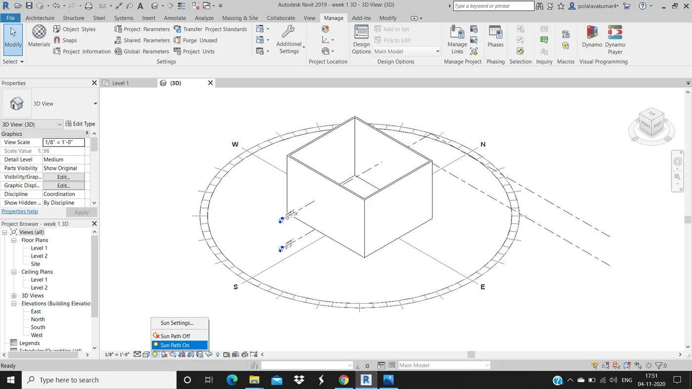
RESULT:
With the help of sun path option we can turn on/off to view shadings in the layout created.
ANS 10)
AIM :
Use the manage tool bar to enter project settings, project name and project issue data.
TOOLS USED:
- Manage tool bar.
- Project information.
- Project issue date.
- Project name.
PROCEDURE :
- Click on manage tool bar on the ribbon.
- Click on project information under project settings.
- Project information dialog box appears.
- Under others enter project issue date and project name(according to our convenience).
- Click on ok.
RESULT :
With the help of manage tool bar we can enter the project settings and change the project issue date and project name.
ANS 11)
Analyze is one of the tools in revit and it is provided in the ribbon, after clicking on the analyze option we get a Analyze tool bar which consist of many tools and options which are helpful in creating the model in revit. In the analyze tool bar we have many tools like Analytical Model which consits of boundary conditions, loads, load cases and load combination. Under the Analytical Model Tools we have adjust, reset, supports and consistency tools. Under spaces and zones we have space, space seperator, space tag, space naming, zone. we have many more tools like reports and supports, check systems, colour fill and energy optimizations. With the help of these tools we can design the models effectively.
ANS 12)
There are many types of links which can be used to link the models, them are:
- Link Revit : This can be used to link another revit model to any current revit model.
- Link IFC : This is used to link IFC file to the current project which can be used as reference and to gather information for use of additional dasign work.
- Link CAD : This is used to link a CAD file to a current revit file.
- DWF Markup : This is used to link marked up DWF files into a revit project. With this we can see the markups on corresponding sheets.
- Point cloud : this helps us to link point cloud file into the current project. They mainly have the file extension as *.rcp or *.rcs.
- Coordination model : this helps to link NWD or NWC file to provide context to the revit model.
- Manage links : This link provides options for managing the links to building models, CAD files, DWF markups files and point clouds.
ANS 13)
Collaborate tab in revit is very useful as we can link multiple Revit models together. A group of team members can have access to work on a single model. Collaborate tab is necessary as we can split the work among the team members and by distribute the work the can complete the work with higher accuracy. Collaborate tab supports modelling and it increases the efficiency as the work is distributed and completed by many members simultaneously so the efficiency is increased.