Week 6- Challenge
OBJECTIVE:
- To mesh the hood model with low tria concentration.
- TO make sure that the model passes all the quality parameters.
GENERAL TRIVIA ABOUT HOOD IN A CAR:
- Hood or bonnet is the main component in the front portion in car. Hood is considered as the frontal BIW closure component. The shape of the hood is made aerodynamic in order to minimise the air resistance. It is used to access the parts like radiator,engine,bsttery e.t.c. Hood can be kept in open position with the help of the support rod, it basically consists of innerpanel, outerpanel,hinges and latch. These are made to redue the air reistance as the air flows through the component. Hood are also used to decorate and provide a luxurious look to the car. It is hinged cover over the engine of the motor vehicles that allows acess to the engine component for repair and maintainence.
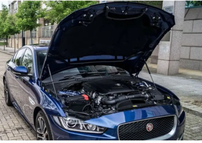
Fig(1). HOOD IN A CAR
CAD MODEL IMAGES:
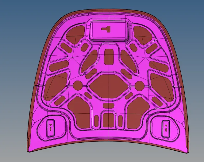
Fig(2). Front view
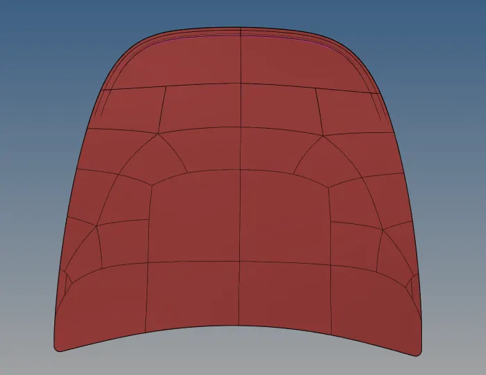
Fig(3). Back view
PROEDURE:
- The prelimnary basic steps are to import the model and perform the topology cleanup, the model can be imported from the import options present at the top of the GUI.
- The model will be present in either step/iges/solidworks format. Select import-click on the model-click on import. The model will be imported, once the model is imported set the model to by topo mode and delete the solids if present by clicking on the delete options. The following set of images illustrtartes this step,
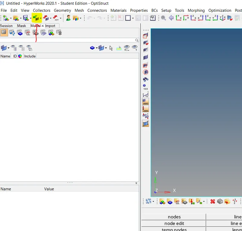
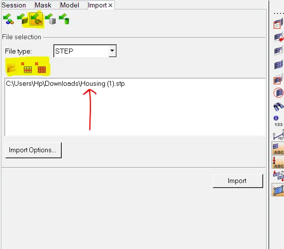
Fig(3). Fig(4)
- Geometry clean up have to be performed on the model, before performing the geometry cleanup select a single component from model and make it current by right clicking on it and selecting it make it current.
- Surfacefillets can be removed from the model if they fail for minimum length. Holes too can be removed if they fail for minimum length. Missing surfaces have to be remade by selecting aptible options available in geometry deck.
- After performing geometry cleanup, the next step is to extract the midsurface from the model.
- Select geometry- select midsurface- select the component - click on midddle mouse button.
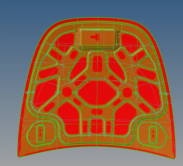
- The midsurface will be generated as shown in the figure, the below set of images expalins this step,

Fig(5)
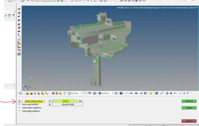
Fig (6)
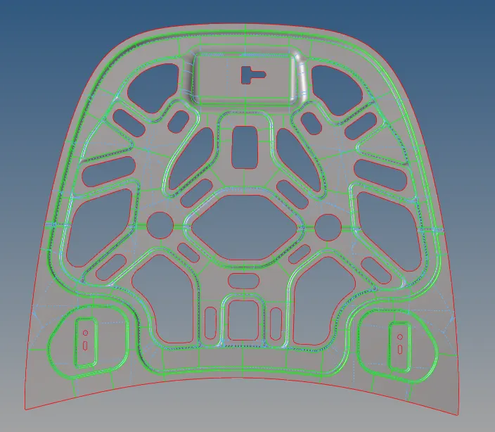
Fig(7). Generated midsurface
- Once the midsurface is generated, cleanup the midsurface to perform the mesh on the model.
- Construction lines, feature lines should be suppressed if they fail for minimum length.
- Create new construction lines at necessary areas, split the surface into smaller surfaces for better capture of the mesh.
- The tools required to perfrom this step are as explained below:
- Geometry-Quickedit-Toggle, this is used to supress the edges.
- Geometry-Quickedit- Split surface- node by node, this is used to split the surface and generte smaller surfaces.
- Geometry-Quickedit- Add/remove point, this is used to add or remove construction points.Similarly varied options are present in the geometry panel, aptible ones must be selected.
- The following is the image of the component after performing geometrycleanup,
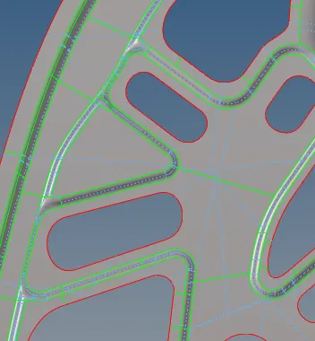
Fig(8). suppresed edges for convineiance
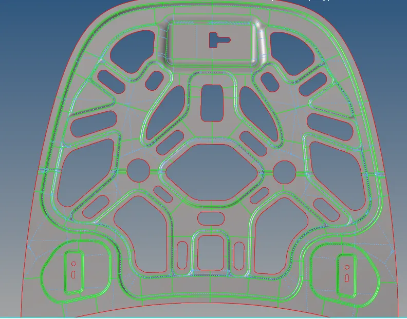
Fig(9). Midsurface after geometry cleanup
- Now the meshing can be done on the midsurface, Before performing the meshing the quality parameters should be entered in the criteria parameters file which is present at the top of the GUI.
- The rootpath for this is select preferences which is at the top of the GUI- select criteria file settings-enter the parameters-click apply-click ok.The criteria file can be saved and reused whenver required.
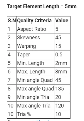
Fig(10). Given quality parameters
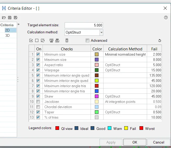
Fig(11). Criteria file settings pannel
- Now to perform 2d meshing on the midsurface, select 2d-automesh- select mixed -set element size to 5- select surface-click ok, the mesh will be generated on the surface.
- Similarly select the surfaces one by one and mesh the model completely,
- For symmmetrial componenets, Mesh can be generated on one side and can be reflected on to the other side by using reflect option.
- The generated mesh elements may fail for some quality criteria such as minimum length,maximum length, warpages e.t.c.
- With the help of the cleanup tools present in the 2D-Quality index panel, we can resolve the elements to not to fail for quality.
- The below are some of the tools that are used to clean the elements,
- Swap edge- This is used to swap the edges of the elements.
- Place node- This is used to adjust the nodes based on the quality.
- Element optimise- This is used to refine the mesh.
- Drag tria - This is used to pull/push the tria elements for better quality
- Split quad- This tool is used to split the quad element.
- Node optimise- This is used to optimise the node.
- Smooth - This option is used for better mesh quality and enhancement of the mesh. Other option are also present that may be used whenever necessary. The below set of images explains this step,

Fig(12). Automesh and other useful tools in 2d panel

Fig(13). Automesh panel

Fig(14). Quality index panel

Fig(15). Smooth panel
- The generated mesh should contain less trias because trias have higher stiffness when compared to quads, so always try to remove the trias wherever possible. Remeshing also helps in removing trias.
- There are some ground rules while handling trias, they are
- There should not be back to back trias.
- Opposite trias have to be eliminated.
- Trias should not be present on the edges of the surfaces.
- Trias should not be present near the holes.
- Trias should not be present on the fillets.
- There should be less trias, The trias concentartion should not be more i.e there should be some considerable distance between the trias.
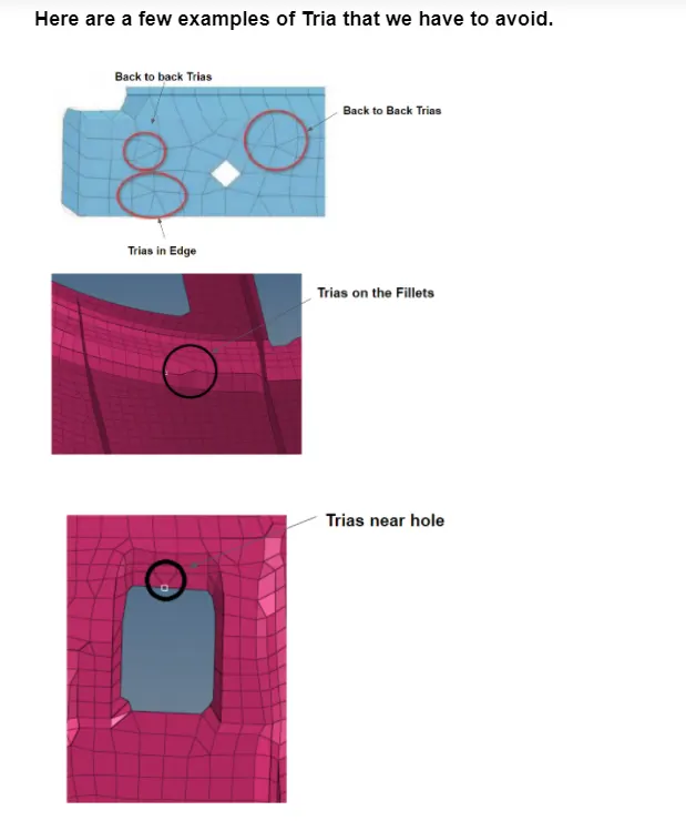
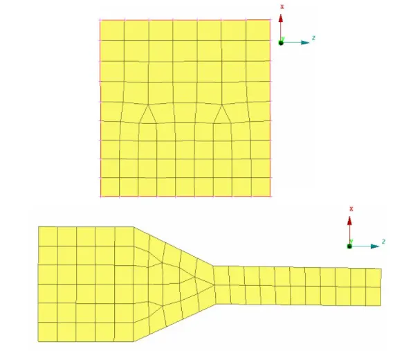
Fig (16). Better mesh flow if trias cant be avoided
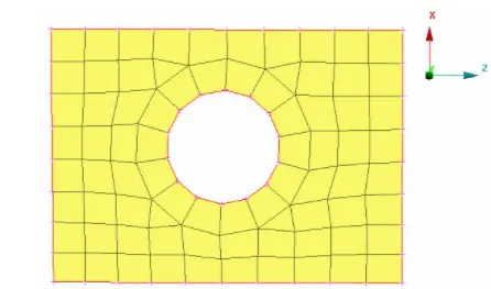
Fig(17). Good capture of hole with less trias
- Reflect option is used for symmetrical components, select reflect from Tools panel.
- Select the surface-specify the axis-specify the base node-click ok.
- After reflecting,check for free edges in the model by selecting edges from the tool panel and remove the free edges by using equiavalence option. The below set of images illustrates this step,

Fig(18). Tools panel
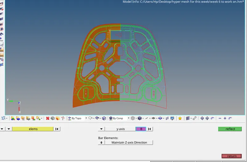
Fig(19). Reflect panel

Fig(20). edges panel
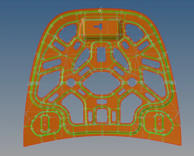
Fig (21). Final image
- All the other components have to be meshed using the same procedure as mentioned above.
RESULT:
- The following are the images of the MODEL after meshing,
INNER PANEL
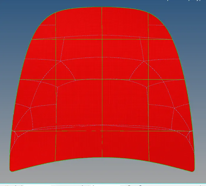
OUTER PANEL
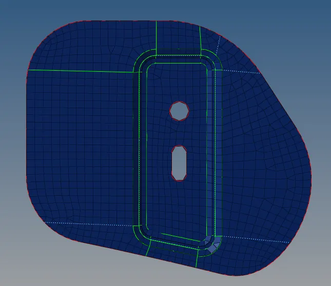
HINGE
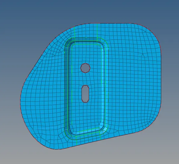
HINGE
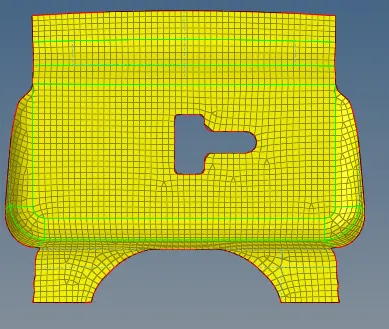
LATCH
HOOD COMPLETE ASSEMBLY