Week 3
OBJECTIVE:
- To cleanup the geometry of the hood and mesh the model with the given quality parameters.
- To assign thickness to each component.
GENERAL TIRVIA ABOUT HOOD :
Hood or bonnet is the main component in the front portion of the car.Hood is considered as the frontal BIW closure component. The shape of the hood is made aerodynamic in order to minimise the air resistance. It is used to acess the parts like radiator, engine, battery e.t.c. Hood can be kept in the open position with the help of the support rod, It basically consists of a innerpanel, outerpanel, Latch, and two hinge components. These are made to reduce the air resistacne as the air flows around the car. Hood are also used to decorate and provide a luxurious look to the car.It is the hinged cover over the engine of the motor vehicles that allows access to the engine component for repair and maintainence.
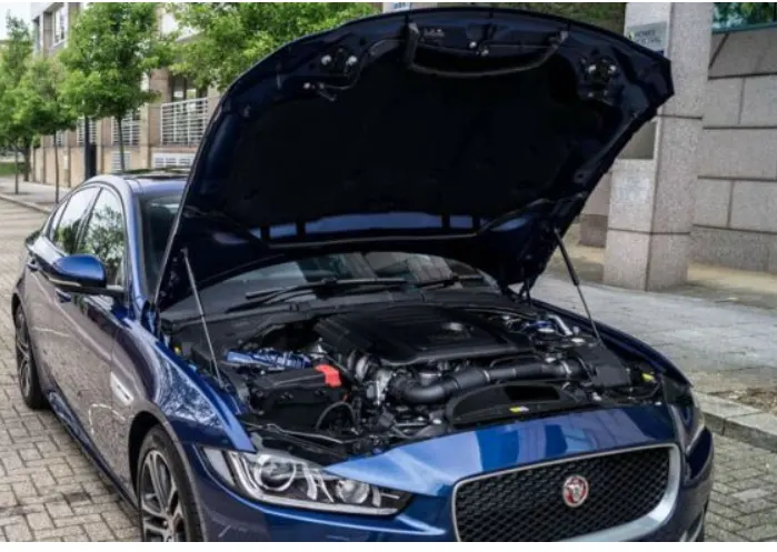
Fig(1). Hood in car
PROCEDURE :
- The basic step or the prelimnary step is to open the model in ansa using "File-open" command, once the model is displayed on the screen, customize the settings according to the usage.
- To perfrom Geometry cleanup on the model, there are some prelimnary steps that has to be performed,
- Orientantion of the model, the root path is Modules button- Faces -Orient .
- Set the model to ENT mode to perform topology clean up, ENT mode displays the model with all the surfaces in the model along with the geometrical errors present in the model.The model is visible as shown in the below image,

Fig(2). Model without topology cleanup
- The entire model should be split into several components based on the property, to do that select the property option at the top of the GUI. A small box pops up as shown in the figure, the components can be organised based on their proprty id also called as PID. In the small box, a bulb like symbol is present, select the bulb symbol for the for the component to get organised from the group. All the other bulb symbols should be turned to grey colour by clicking on them. The below figure explains this step,
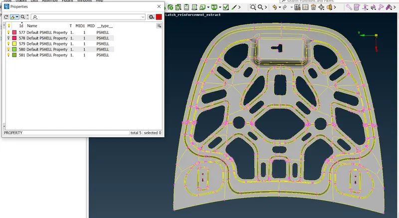
Fig (3). Differentiation of models based on the components.
- Select the topo mode to perform the geometrical cleanup on the model, to find the errors present in the model select geometry from the checks manager and select the component- select the parameters-click on execute. Ansa will detect the errors in the model as shown in the below figure. In the popup box there will be a option called Autofix. Autofix clears the error automatically, but this is not advisable. clear the errors manually by selecting aptible tools from the Faces panel in the topo mode. The below figures displays this step,
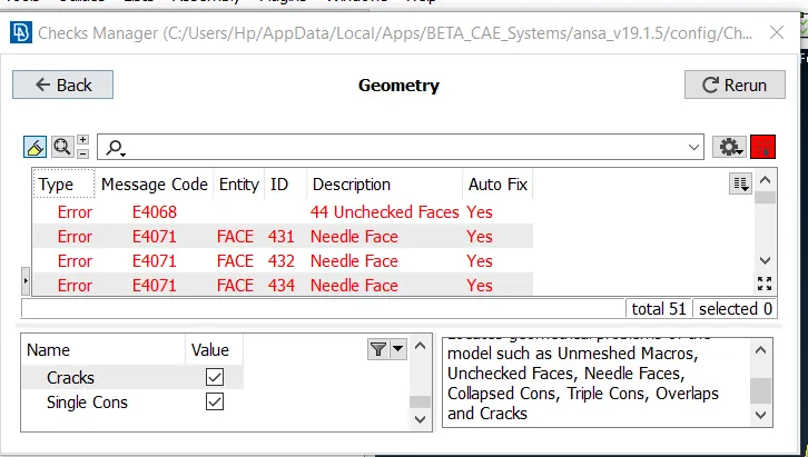
Fig(4). Geometry checks manager display.
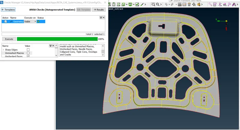
Fig(5). After fixing the errors in the component
- The next important step is to extract the midsurface from the model. Midsurface extraction can be done in two ways, One is by using MIDSURFACE from Faces panel in the topomode and the seond method is by using the OFFSET option from the Faces panel in the topo mode. The two methods are explained below,
- USING MIDSURFACE option from the Faces panel in topomode:
- Select the midsurface option from the faces panel-Select the component.
- The component will be divided into three regions based on the colours RED,BLUE,GREEN. RED and GREEN colour must be the inner and outer surfaces of the component, the blue colour should lie in between them, This can be seen in the below figure,
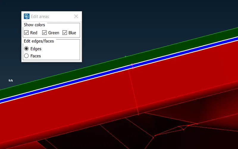
Fig(6).
- A small box pops up after selecting the middlemouse button, Specify the offset direction, in the display box the offset distance and thickness are specified automatially by ansa, select the midlle mouse button to continue,
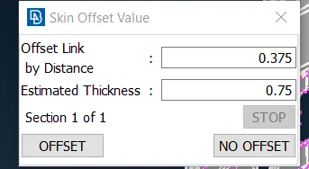
- ANSA will create the midsurface as shown in the below image, The parent component will get automatically deleted once the midsurface is generated. This is also one of the reasons for not advising this method to generate the midsurface.
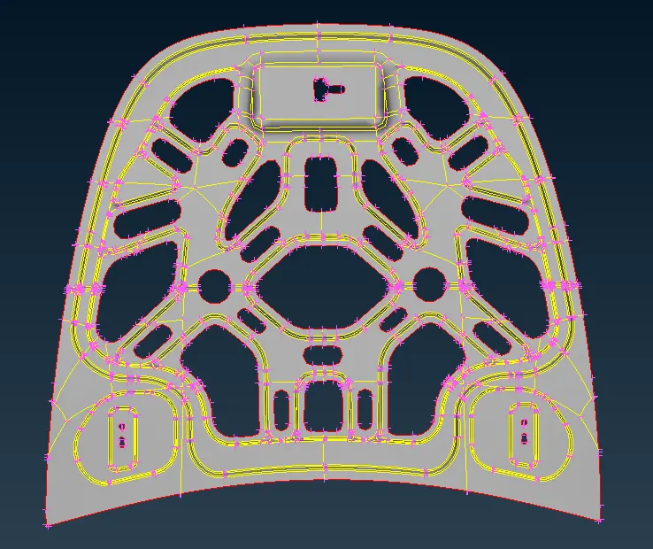
Fig.(7) generated midsurface
- USING OFFSET OPTION FROM THE FACES PANEL IN TOPOMODE:
- Select the offset option from faces panel.
- Select the PID region-select the feature angle- select any one surface on the component, the other surfaces will get automatically selected, in case if they are not selected select them.
- Specify the direction and specify the distance.
- ANSA popsup a small box asking to delete the original faces, select NO.The midsurface will be generated exactly in the middle. This can be shown in the below figure,
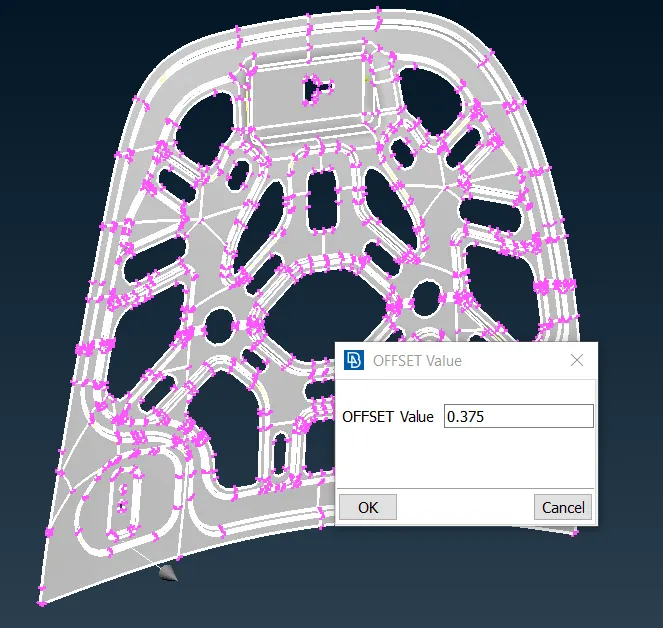
Fig(8).
- The midsurface generated has to be separated from the model. This can be done assigning new property to the midsurface.
- To create the property, select the property option and rightclick anywhere in the property display box.
- Select Create-new-PSHELL-PSHELL.
- A small popup box appears, fill all the necessary parameters, and click OK. A new property will be generated in the propety tab,This can be seen in the below image,
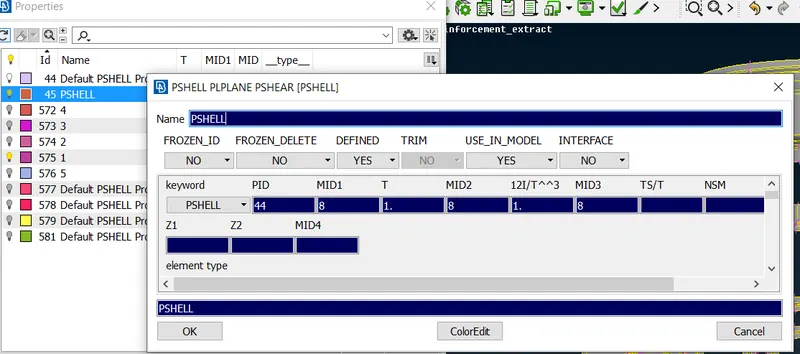
Fig(9)
- To assign this property to the parent geometry, right click on the propetry and select the assign option.
- select the PID midregion, and click on the surface.
- select the middllemouse button, the property will be assigned to the parent geometry.
- Separate the midsurface by clicking on the bulb symbol, the midsurface will be generated as shown in the below figure,
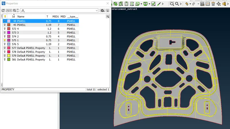
- Generally it is advisable to generate the middlesurface using offset option rather than automidsurfacing, this is advised because for complex geomtries automidsurafcing will create too many errors.
- After generating the midsurface the next step is to mesh the model, The following sequence of steps expalin this process completely,
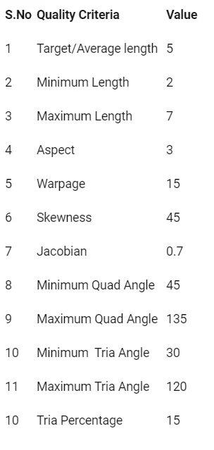
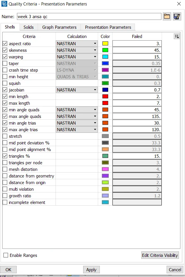
- The first step or prelimnary step is to specify the parametry file and criteria file, The given parameters and criteria file can be as shown in the below image,
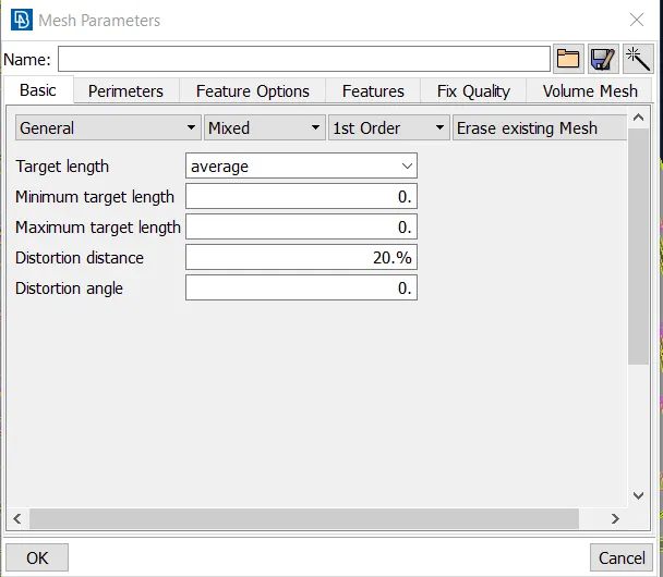
- The given target element size is 5, the tolerane values are 2 and 7. Enter this values in the parametery options by selecting on the parametry tab. This is as shown in the below figure,
Before entering the quality parameters, here is a general trivia about them.
- Minimum and maximum length specify the allowable element size which are 2 and 7 in this component.
- Aspect ratio is the ratio of maximum length to minimum length in a element. Here it is 3.
- Warpage is the angle of plane deviation when two normals are extended from a quad element. Here the warpage is 15.
- Skewness is the quality of element in angular terms.Here it is 45.
- Jacobian is the size of the ideal element. Here it is 0.7
- The values of other factors such as minimum angle tria, maximum angle tria, minimum angle quad, maximum angle quad are as listed in the above figure.
- The quality criteria values have to be enetered in the quality criteria tab by clicking on it. These values may be saved and used again if needed. The below figure shows this step,
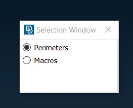
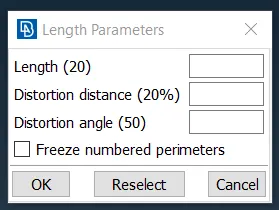
- After entering both the parameters file and criteria file, Set the model to mesh mode which is beside the topo mode. The prelimnary step is to adjust the length between the hotpoints to 5 throught the model as the target length is 5. This can be done by selecting the perimeters-length-perimeters- enter the length value as 5, then again select peimeters-length-macros-perimeters-set the length to 5. click ok. This step can be shown in the below fig,
- Now the model is ready to mesh,mesh the model surface by surface, Make necessary cuts, add construction lines.The tools mostly used in mesh deck are:
- Mesh generation - Spot mesh/best mesh, this tool is used to generate mesh on the surface.
- Shell mesh - smooth/reconstruction, this tools are used to enhane the exsisting mesh and to reduce the number of trias.
- Elements- split/join, Grid- paste , these tools are used for fixing element quality. The below images explains these steps,
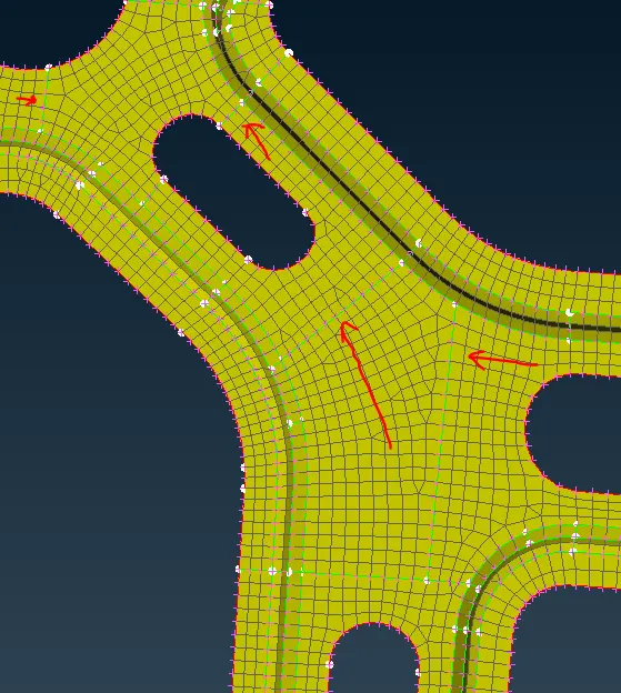
fig(15). Surfaces divided using macros-cut
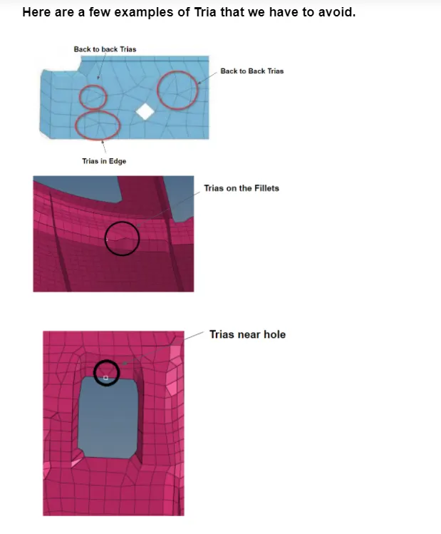
fig (16). Trias should be avoided for durability ananlysis.
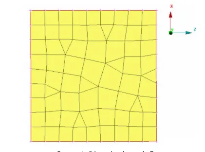
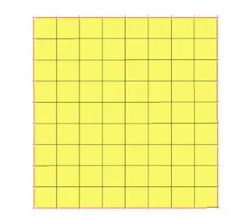
fig(17). poor quality mesh fig(18). enhanced mesh
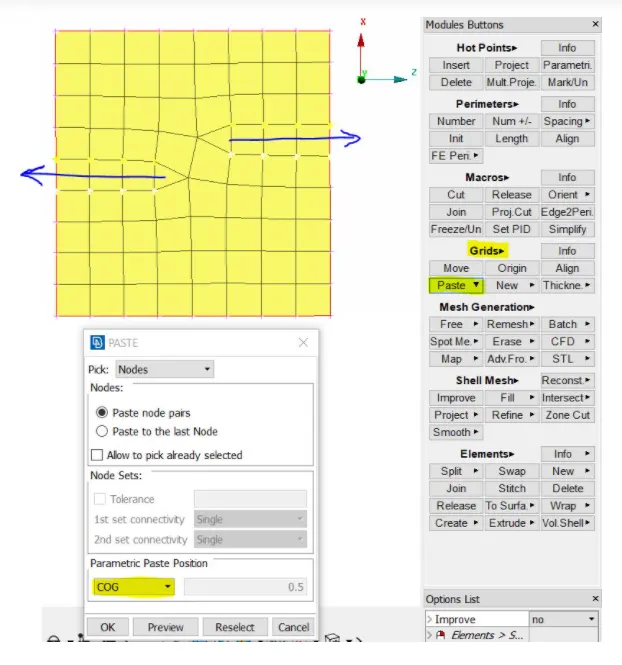
fig(19). Opposite trias removed using paste option.
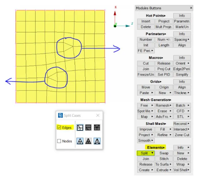
fig(20). Opposite trias removed using split option.
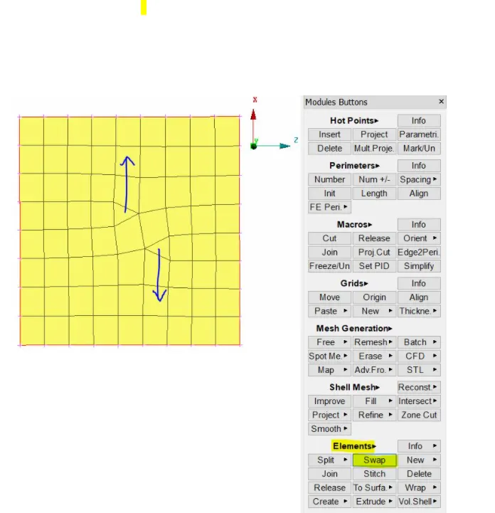
fig(21). Opposite trias removed using swap
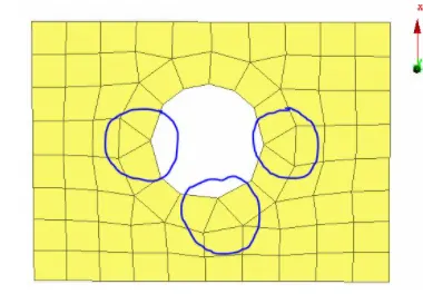
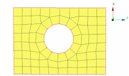
fig(22). Trias should be removed near cirlcles, holes fig(23).
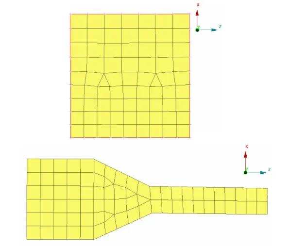
fig(24). Better mesh flow inluding trias removing rotating quads.
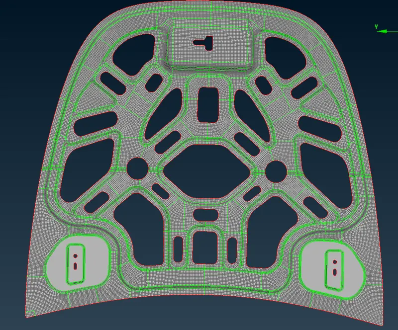
- Mehsing can be done on one side and can be transformed to the other side using transform option in case of symmetrial components, To perform this delete the part that is not meshed.
- Select the transform option which is above the GUI- select copy- select the component - select the symmetrial plane to transfrom-select PID, part and offset, click on middle mouse button, the component will be transformed onto the symmetrical side. This step can be better understood with the following pictures,

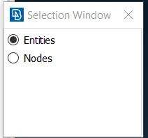
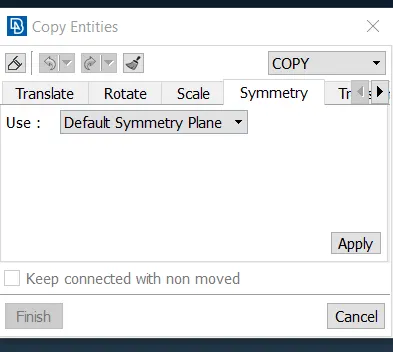
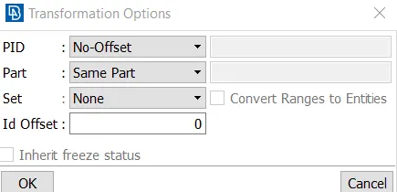
- The above set of images explains transfrom step.
 \
\
fig (25). mesh generated on the other side using transform
- All the remaining components should be meshed by the above mentioned methods.The following are the images of the meshed models,
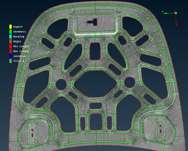
INNER PANEL
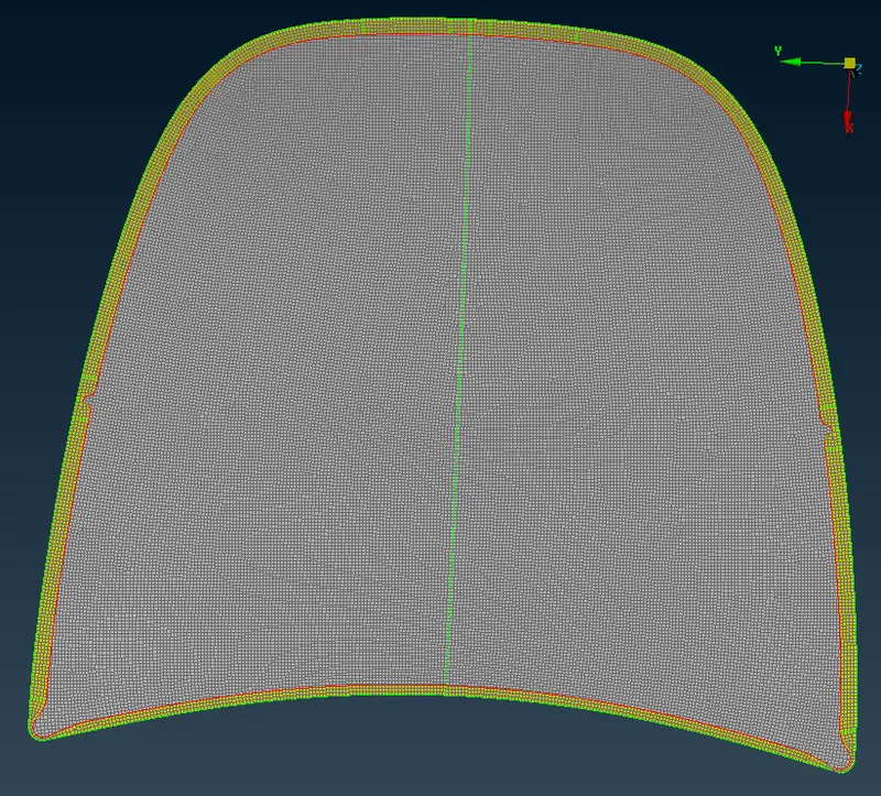
OUTER PANEL
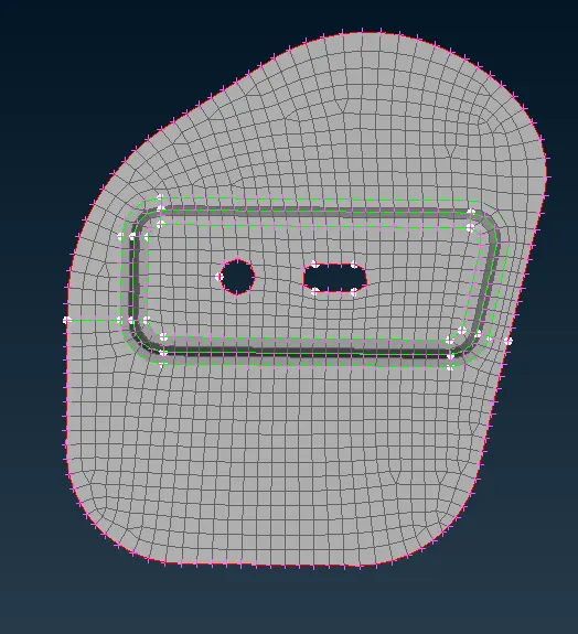
HINGE
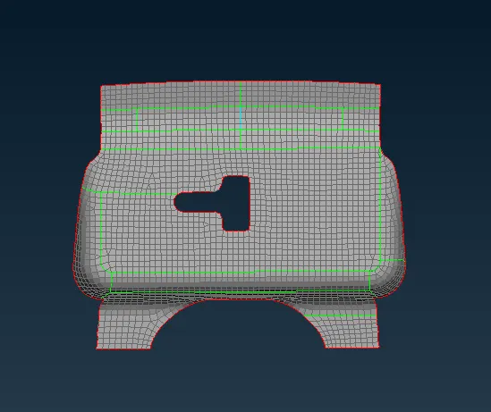
LATCH
LEARNING OUTCOMES:
- Understood how to generate 2d meshing with all the quality criteria.
- Understood why manual midsurfacing is advisable over automidsurface.
- Understood how to use transform option.
- Understood how mesh panel tools helps in generating and enhaning the mesh.
CONCLUSION :
- From this one can conclude that due to the varied options available in ansa 2d meshing can be generated easily within less time and increase the produtivity of the OEM.