Meshing of a Car Hood using Hypermesh
INTRODUCTION
The car hood can be seen in different shapes and sizes. It safeguards the engine parts from the atmosphere, ensures its safety, and also provides a smooth flow of wind over the car, while the car is running, which helps in providing the car a good aerodynamic performance. These are the most important benefits of the front hood of a car. Another important benefit of a hood is that it absorbs the energy of front or side impact.
Parts like the front bumper and hood are designed by the design engineers with the aim that it will absorb most of the energy that might come from any kind of impact which leads to the minimal transfer of energy to the driver or passengers. Minimum the transfer of energy to the driver, maximum the driver would be safe from impact.
To visualize the incidence that could happen in the worst-case like road accidents, earlier crash tests were used to perform putting dummies of the driver and the passengers in the car. The results were useful but the problem was with the cost it incurs on the company and the time limit. Moreover, they couldn’t make slight changes in the environment to see the results. CAE or computer-aided engineering is the field of engineering which works from designing a part or assembly, keeping in mind the manufacturing process available to its virtual testing using programmed mathematical algorithms.
The most important advantage of using CAE or virtual testing is that we can change the kind of force or the amount of force, the material, or we can make slight changes in design to check the after-effects, just by changing the boundary conditions or defining different materials, etc. Such things would be very costly with the actual testing procedure. However, it doesn’t mean that actual testing is not necessary. Prototype testing or actual testing and virtual testing always work coherently.
- Aim
To obtain the discretized car hood model for the virtual analysis.
- Objective
To prepare the car hood model for the virtual analysis by discretizing it into a finite number of elements.
PROCEDURE
The hood model was comprised of 5 parts including the outer extract, the inner extract, the latch reinforcement extract, and two hinge reinforcement extracts. Each part was kept as different components. To obtain the completely discretized or meshed hood model, each part had to have meshed separately. The inner extract had many different features in it; thus, it was taken firstly for meshing. The five different parts can be seen below.
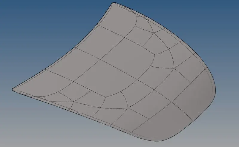
Figure 1: The outer extract.
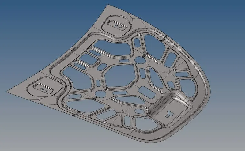
Figure 2: The inner extract.
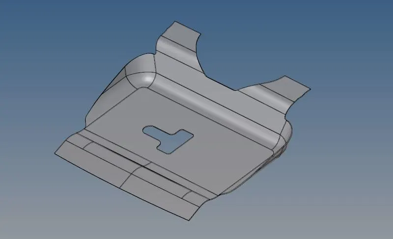
Figure 3: The latch reinforcement extract.
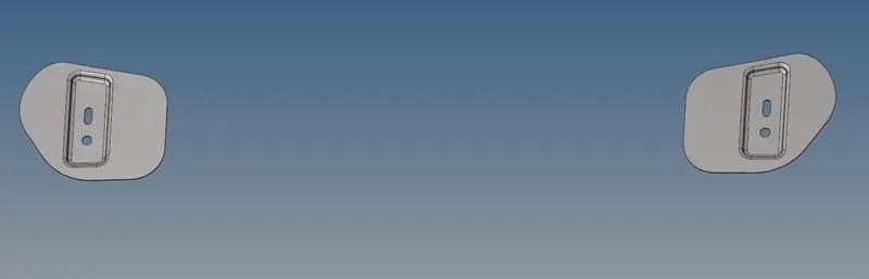
Figure 4: The hinge reinforcement extract.
- Geometry Clean-up
The primary stage of meshing any part is its clean-up. The part was created in any modeling software and opened in another, because of the change in the format of the file some errors occur in the geometry. This might include over-constrained lines, under-constrained lines, missing faces or duplicate faces, etc. A part can be comprised of so many faces. Each face has to be connected with the neighboring faces. This connection is represented by a green line and if this connection is missing between any two neighboring faces, it is represented by a red-line which is also a free edge of that particular face. The line can also be suppressed if no division between faces is required. Fig. 5 shows the presence of these three kinds of lines.
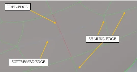
Figure 5: Different kinds of edges.
To make line free, or connect, or suppress, there is an option called the ‘toggle edge’ in the Geom→quick edit. It can also be used from the Geom→edge edit→toggle.
In 2d meshing, the elements are deployed on a surface of no thickness or midsurface. Solid parts have no role in 2d meshing. Therefore, before cleaning the geometry, it is necessary to check if any solids present in the model. If present, it should be deleted.
- Extracting Mid-surface
After cleaning the geometry, the next stage of the procedure is to obtain the mid-surface of the complete part. The mid-surface is the middle-most surface of the sheet metal part which has no thickness. A property is assigned separately to that mid-surface which defines its thickness. The reason behind extracting the mid-surface is to reduce the computational time. 3-d elements take more computational time to solve the problem compare to 2-d elements. For the sheet metal and plastic components parts with thickness less than 5-6 mm, generally, 2-d elements are used.
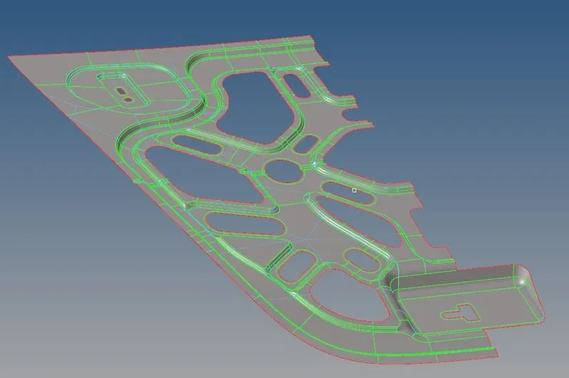
Figure 6: Mid-surface of half portion of the hood’s inner extract.
- Preparation for meshing
While meshing a part, the flow of elements has to be smooth for a smooth flow of energy. To maintain the smooth flow of energy some other criteria are like no trias should be facing each other, trias shouldn’t be present at the edge, etc. Rotating quads are also not required, however, if it is an NVH simulation, it is okay to keep rotating quad rather than tria element. It is because, in NVH, the concern is not about the development of stresses like the simulation of durability or fatigue. Tria elements are generally kept very limited. Though the mesh flow, and thus the energy flow, can be maintained using tria elements, the simulation results slightly deviate from the actual value.
Therefore, to mesh the complete geometry with the smooth flow of elements, the geometry is split into several smaller parts bearing in mind that it will not disturb any feature of the geometry. Thus, meshing and observation of the smaller parts become easier.
- Setting Quality Criteria
2d meshing is basically performed using two types of elements viz. quads and trias (or squares and triangles). As good the quality of meshing as good the results we get after solving the problem. The quality of mesh depends on the quality of an element. An ideal element has to be a perfect square or perfect triangle. But due to changes in the shape of the model, the triangle and square elements change slightly. These changes can be in their lengths or angles. To mesh the model with only ideal elements is very difficult. Thus, a criterion is always set for the quality of elements based on some parameters viz. the aspect ratio, the warpage, the minimum, and maximum length, etc. of an element. Quality criteria required are set and it is provided to the CAE team. Depending on the criteria, the part is meshed. The criteria provided for this part is as shown in the below table:
Table 1: Quality criteria for elements.
| Target/Average length | 5 mm |
| Aspect | 5 |
| Skewness | 45 |
| Warpage | 15 |
| Taper | 0.5 |
| Minimum length | 2 mm |
| Maximum length | 8 mm |
| Minimum Quad Angle | 45 |
| Maximum Quad Angle | 135 |
| Minimum Tria Angle | 20 |
| Maximum Tria Angle | 120 |
| Tria Percentage | 10% |
The quality of the elements required is set by clicking the Preferences→Criteria file settings, in the menu bar. A dialog box would open as shown in fig.7 in which a required quality criterion can be set.
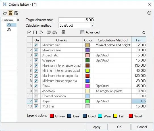
Figure 7: Dialog box that opens after clicking the Preferences→Criteria file settings in the menu bar to set quality parameters of elements.
- Discretization or meshing
Once the quality of elements is set, the next stage is the meshing of the model. To mesh the model, there is an option called ‘automesh’ in the 2D section. Using this tool, the faces of the model is meshed on-by-one. The figures below show all the meshed parts of the hood model.
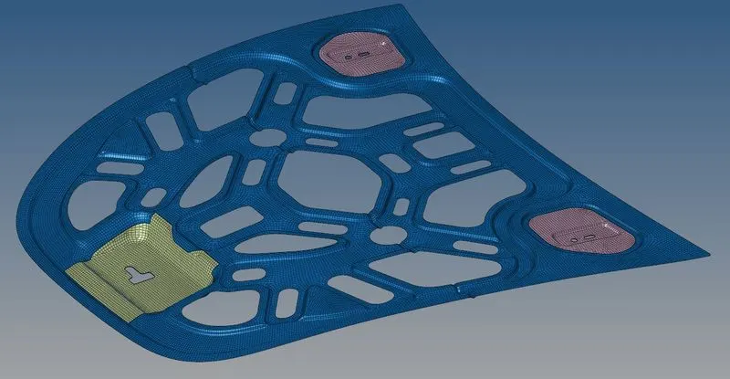
Figure 7. Meshed inner extract, the latch reinforcement extracts, and the two hinge reinforcement extracts.
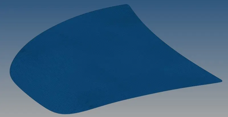
Figure 8: Meshed outer extract.
- Quality Check
After completing the meshing part, the last stage of the process is to check if all the elements are within the set criteria or not. To do that, there is an option called ‘elems check’ in the Tool section. When clicked, a window of a set of quality parameters opens as shown in fig. 9.

Figure 9: Window to check failed elements.
Once the failed elements are found it has to be corrected manually. It can be done by using the different tools available in 2D→qualityindex→cleanup tools, as shown in fig. 10.
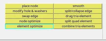
Figure 10: Tools available in qualityindex option to correct the element quality.
One more thing to check in the meshed part is that no free edges are present in between elements apart from the perimeter. Using Tool→edges, free edges can be found out. The free edge is shown as a red line as shown in fig. 11.
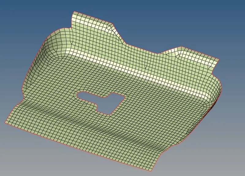
Figure 11: Presence of free edge on perimeter.
The presence of free edge on the perimeter is allowed, however, its presence in between the elements indicates that the elements are not connected, as shown in fig. 12. In such a case, elements have to be connected manually. If the distance between nodes is too small, then using Tool→edges→equivalence, elements can be connected. But if the distance is large enough and the nodes also mismatching, then nodes has to be moved to the proper place using 2D→replace.

Figure 12: Nodes misplaced or elements not connected.
After moving the nodes, it would appear like the normal flow of elements, as shown in fig. 13.

Figure 13: Nodes moved to connect elements and maintain the flow.
One more thing to check for elements is that the vectors of normals should be in the same direction. Using Tool→normals, the vector direction of the normals of elements can be checked. Ideally, all vectors should be in the same direction as shown in fig. 14.
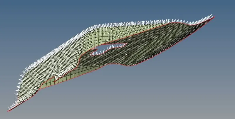
Figure 14: Normal vectors in the same directions.
LEARNING OUTCOME
- Toggle option is used to connect edge, suppress edge, or make the edge free.
- Solids have to be deleted in 2d meshing.
- Maintaining the smooth flow of elements becomes easier by splitting the geometry into smaller parts.
- No feature should be disturbed while splitting the geometry or making any modification.
- No trias should be directly facing each other. In other words, opposite trias shouldn’t be present.
- The rotating element should not be present.
- No tria element should be at the edge of the perimeter.
CONCLUSION
Meshing a model is the primary and important stage of virtual testing. Thus, while meshing the geometry with quad/tria elements, attention should be given to maintain the mesh flow. Because if it has gone wrong, the result would be inaccurate and thus would be the waste of time and money.