Week 6- Challenge
Meshing the engine hood using hyperworks
Aim :- To clean geometry, generate midsurface and mesh the hood component in given quality criteria.
Given Quality criteria :-
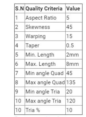
Software used :- Altair Hyperworks 2020-Student version-optistruct
Methodology :-
- Import CAD geometric model into hyperworks.
- Geometry cleanup and topology
- Extraction of mid surface and autoclean-up for meshing
- Meshing
- Mesh flow improvement and eliminating quality fail elements.
- Checking of meshed model.
Procedure :-
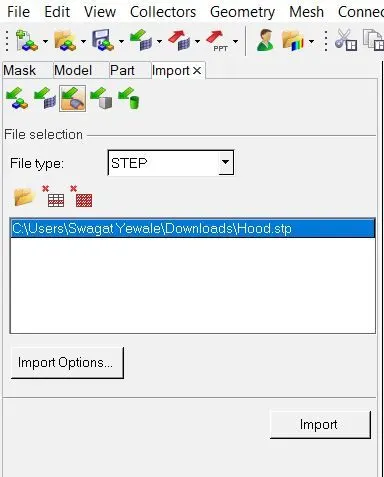
1. Import CAD geometry into hyperworks. :- Import CAD geometry in hyperworks by using Import Geometry > Select file type as .STEP > Select file > Import option as shown in below image.
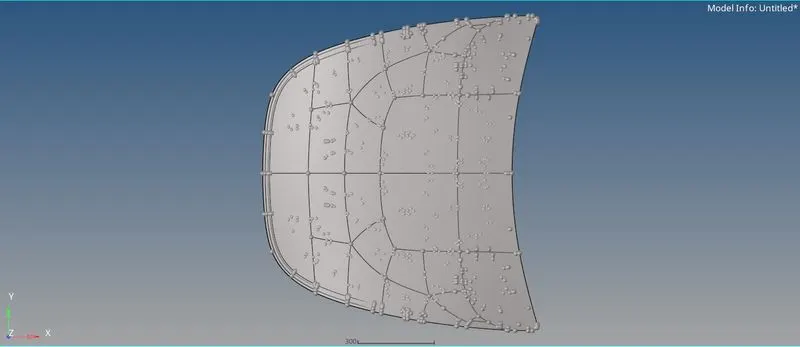
2. Geometry cleanup and topology :- After importing model into hyperworks surfaces gets distorted, duplicated or erased so after importing model into hyperworks need to do geometry cleanup here after importing no missing surface or duplicate surface found so we can move further.

3.Extraction of mid surface and autoclean-up for meshing :- Here, given componenet is sheet metal componenet having uniform thickness and having thickness less than 5 mm so we can move further with 2 D meshing. For 2D meshing need to extract mid surface and meshed it with properly so that mesh can represent surface during simulation. Here i extracted mid with Geometry > Midsurface > Select skin offset extraction option > select surface ( Select surface one by one ) > Create option.
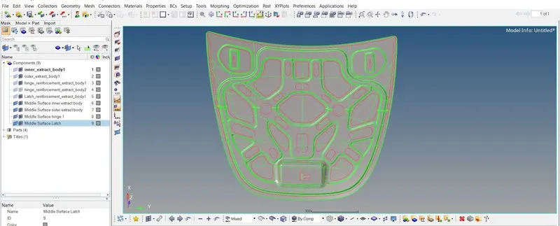

After extraction of mid surface autocleanup the geometry for meshing purpose by Geometry > Autocleanup > Select mid surface > Proceed option it will automatically toggle the edges where meshng quality criteria will fail.

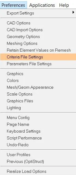
4. Meshing :- After generating mid suraface we can move to meshing here i used automesh for meshing. Before meshing i assigned the quality parameters by Toolbar > Preference > Criteria file settings > Assign the given values as shown in image below.
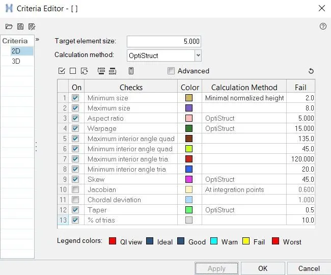
Quality parameters :-
- Warp angle :- It is angle between normal of two planes of quad element by spliting it diagonally. The ideal value of wrap angle is 0 degree but it is allowable till 15 degree.
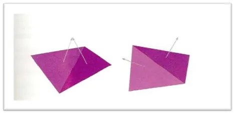
Fig. 4.1 Warp angle
- Aspect ratio : It is defined as maximum edge length of element to the minimum edge length of element. Ideal value is 1 but it is acceptable till 5
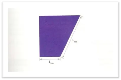
Fig 4.2 Aspect ratio
- Skewness : Skew for quad element = 90 ° – minimum angle between two lines joining opposite mid mid sides of element. (α )
Skew for tria element = 90° - minimum angle between two lines from each node to opposing mid-side and between two adjucent mid-side at each node of elements. Ideal value is 0° and acceptable till 45°
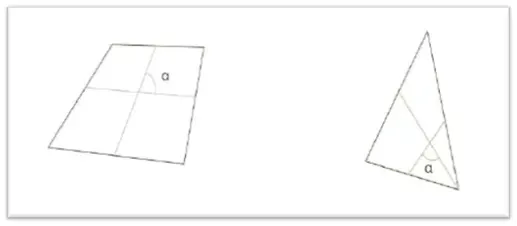
Fig. 4.3 Skewness
- Jacobian :- It is scale factor which arises due to transformation of co-ordinate system. Ideal value is 1 but it is acceptable greater than 0.6
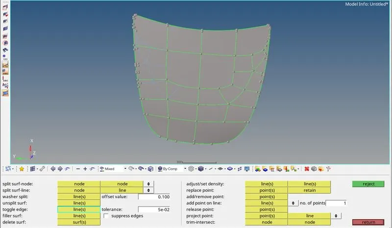
Before going to meshing need to devide surface in square or rectangular parts for better mesh flow pattern. here as shown in below image on left hand side surface is devided in small parts for better mesh flow pattern
As surface of hood is symmetric in Y-axis so i deleted half of portion alon Y-axis except latch surface as shown in below image so i can mesh half of portion and remaining one is can be generated automatically by reflect option so that it will take less time for compliting project.
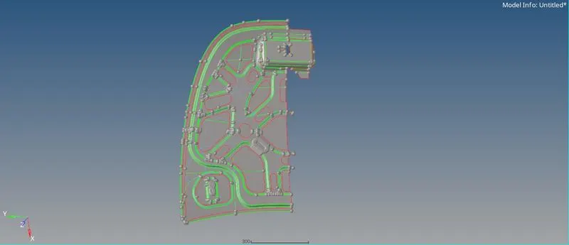
Mesh the surface part by part by using 2D > Automesh > select surface > select mesh size 5 mm > mesh option as shown in image below

5. Mesh flow improvement and eliminating quality fail elements. :- After meshing need to check elements which are violating thresholds, for that go to 2D > Quality index option it will highlight the elements which are not as per assigned quality criteria. For eleminating these elements need to use 2D > Quality index > Cleaning tool option in that we can use smooth, element optimization, node optimization, place node, drag tria element, combine tria element, etc options as shown in image below.

For better mesh flow pattern following practices need to followed :
1.Tria should not face to each other as shown in below image also back to back tria element should be avoided.
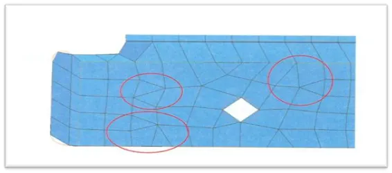
Fig. 5.1 Back to back tria should be avoided
2. On a plane surface tria should be avoided
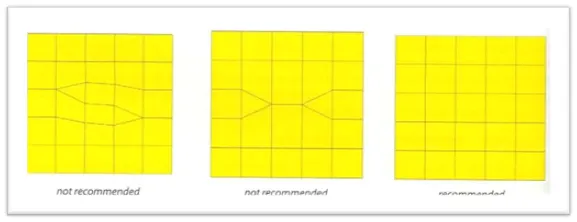
Fig. 5.2 On plane surface tria should avoided
3. Avoid tria at outer perimeter and near to holes.
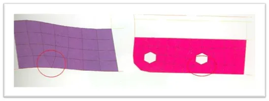
Fig.5.3 Tria should not present on perimeter and holes
4. Nodes should lie on surface no kinks,raise or deep present in model.
5. Avoid zig-zag mesh flow pattern
6. No rotating mesh flow patteren present near holes.
7. Holes should be even number of nodes and its edge should be parallel to nearest parameter.
8. Divide the surface in smaller parts by cut option and after meshing remove it by join option for better mesh flow pattern.
9. Defeature the area where quality parameters fails.
6. Checking of meshed model. :- After improving mesh flow and eliminating of all quality check need to reflect model to get complete model for that use Tools > Reflect > Select displayed elements > select duplicate > Current componenet > Along Y-axis > Maintain Z-axis > select base node > reflect option it will reflect all the elements along Y-axis as shown in image below.
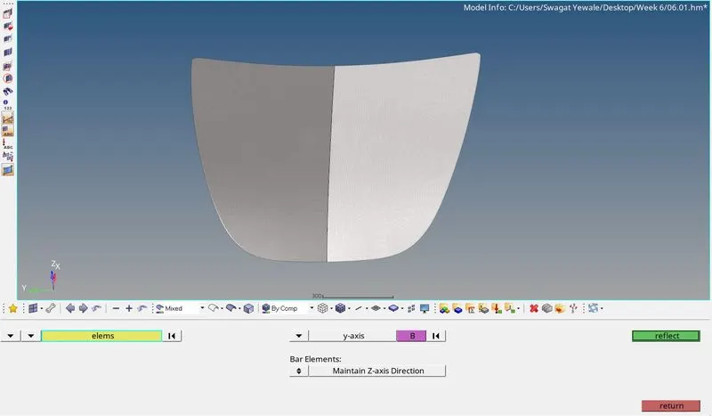
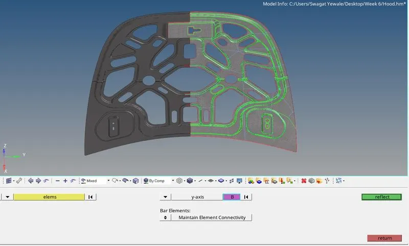
After that check mesh as shown in following points :-
1. Check edges :- By using Tools > edges > Find edges it will highlight the edged. check manually are edges should be on perimeter.
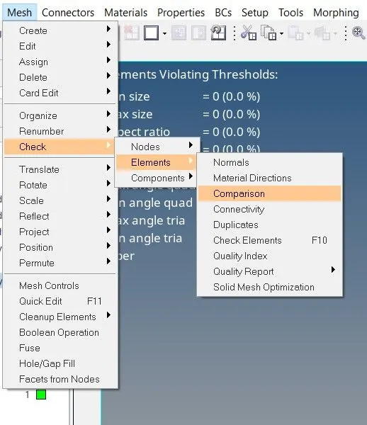
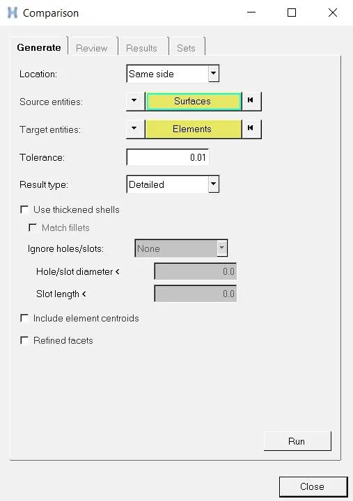
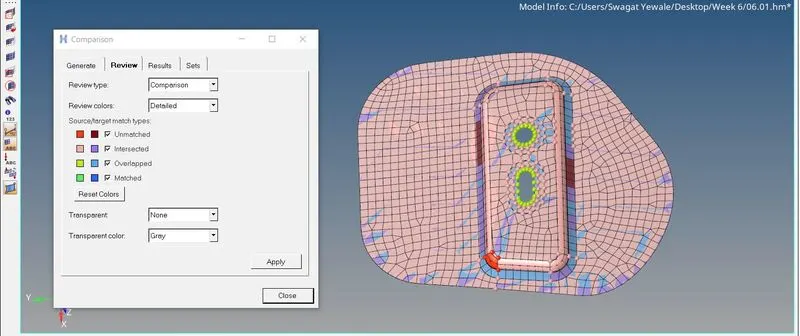
2. Check elements to surface :- For checking elements are captured geometry properly or not this option is used for using this check use Toolbar > Mesh > Check > Elements > comparison > Select element > Select surface > run option as shown in below image. It will shows colored element, red elements means elements are not captured geometry properly, yellow means fine, pink means fine and blue means element captured geometry properly.
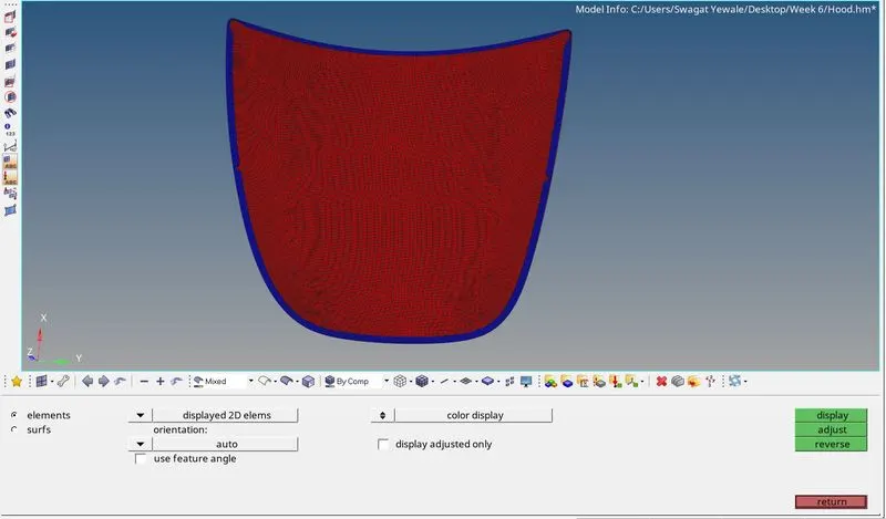
3. Check elements normal :- In this check we check the direction of elemements because during simulation if any external force apply it should simulate in proper direction if normal of element is wrong it will not give proper results so this check is very much important. For using this check go to Tools > Normals > Display it will shows elements in green color of red color as per its orientation as shown in below image. If it is different in color according to its orientation then need to change its direction by selecting that elements and clicking on reverse option.
4. Check duplicates :- This checks the duplicate element generated during meshing for using this option go to tools > Check elemenet > Duplicates option it will highlight number of duplicate elements at status bar if duplicates element found click on save failed and go to delete option click on elements select retrive and delete elements.
Final View of model :-
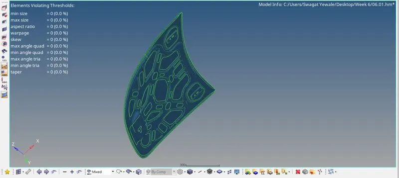
Result :- Thus, the hood model is meshed properly with better mesh flow pattern and as per given quality criteria and model is ready for further processing.