Week 6- Challenge [CLEANING UP GEOMETRY AND GENERATING 2D MESH, QUALITY CHECK]
#WEEK 6 CHALLENGE
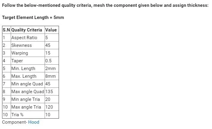
AIM: To clean up geometry and mesh the Hood or its components.
ABSTRACT : The Hood is the hinged cover over the engine of motor vehicles. It gives a good look and style to the car. Hood can open to allow access to the engine components, radiator etc for maintenance and repair. Hood is generally made up of sheet metal,Its shape and material selection can vary as per its applications. Hood is designed to reduce the injuries of passengers or driver while mating with an accident or any collision, so its objective is to reduce the injuries for that having suitable thickness of hood is necessary. Hood is initially designed in CATIA and then can retrieve it to Hyperworks for meshing.
OBJECTIVES: Meshing the components of hood- Inner body, Outer body, Hinges and Latch
with following quality criteria -
Target element length 5mm
Minimum element length 2mm
Maximum element length 8mm
Minimum quad angle 45
Maximum quad angle 135
Minimum angle tria 20
Maximum angle tria 120
Tria percentage 10
Aspect ratio 5
Skewness 45
Warping 15
Taper 0.5
PROCEDURE FOR MESHING:
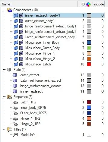
CAD model is imported into Hyperworks, it is in the .stp extension. After importing we can see five components of hood in model tree that are inner extracted body, outer extracted body, latch reinforcement body, hinge reinforcement extracted body 1 and 2.
STEP 1: We can start meshing from the inner extracted body and disabling other components.
Initially we have to create the mid surface of the component.
*Geom>mid surface>auto extraction>select component>extract
- After creating a mid surface we have to clean up the geometry on the surface.
STEP 2: We can mask the one side of the component because it is a symmetric component.
*2D>connectors>mask>surface>mask or (F5)
- We can see free edges, unsuppressed lines and suppressed lines
*Toolbar>By topo
STEP 3: We have to toggle the unnecessary lines and remove free points. We can split surfaces which will help us to mesh the surface properly and adding points to create a split surface by node or line.
*Geom>quick edit or (F11)
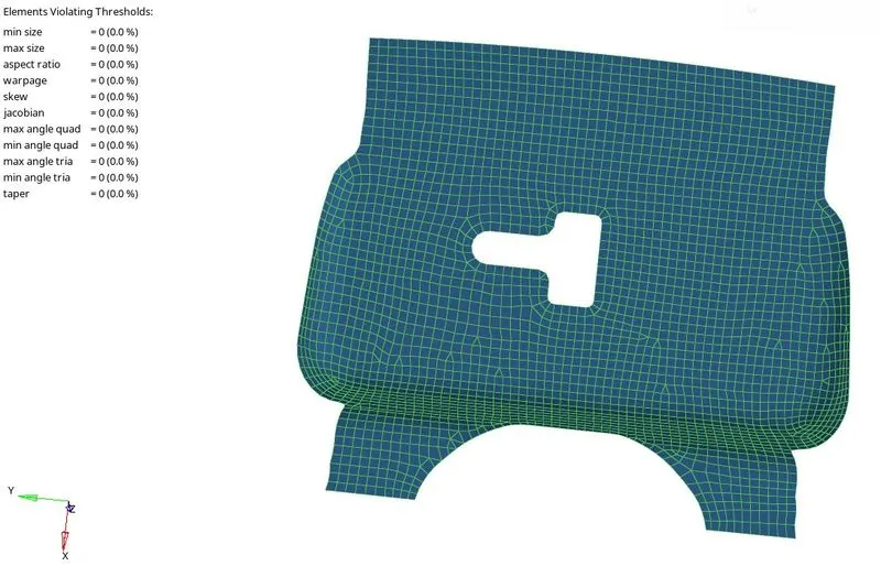
STEP 4: After completing the clean up geometry now we have to perform meshing on mid surface.
*2D>automesh>element size>surface>select surface>mesh or (F12)
- After meshing occurs we have to align the elements to proper mesh flow.
STEP 5: We have to mind the given quality criteria, we can check elements by following command-
*Toolbar>element colour mode>by element quality
STEP 6: Now we can see symbols of the failing elements on the left side of the graphic screen and we can fix it by following commands-
*2D>quality index>cleanup tools>place node/drag trias/split quad element/element optimize

STEP 7: Merging of elements’s nodes if not connected.
*2D>replace>select replace node>with node or (F3)
STEP 8: If there is any vacancy of element or have to combine or split the element.
*2D>edit element>create/combine/split or (F6)
STEP 9: Alignments of element’s node
*Geom>node edit>1st node>2nd node>select node>align or (F7)
STEP 10: If elements lines are not aligned properly we can smooth it to look pleasant.
*2D>smooth>plates>select elements>smooth or (Shift + F12)
STEP 11: Checking of free edges
*Tool>edges>surface>set tolerance>find edges>preview equivalence>equivalence or (Shift + F3)
STEP 12: The component which are symmetric and worked on half of the surface now we have to again reflect it back
*Tool>reflect>element>select elements>set axis>base node>reflect
STEP 13: we’ve to organise the mid surface and mesh elements to parent component.
-Make the midsurface component as current component and then follow following command (Shift + F11)
*Tool>organise>collectors>surface>select surface>move
*Tool>organise>collectors>elements>select elements>move
- After moving all arganise components to its parent component we can delete organised component.
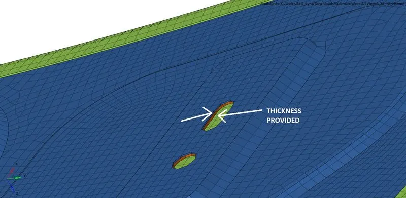
STEP 14: We’ve to assign thickness to the meshed elements, commands are-
-First we should know the thickness of the original component by distance command or F4.
*Model tree>Create>property>name_(thickness)
*Model tree(component)>select mid surfaced component>assign>property[(name_(thickness)]>apply
-After assigning thickness we can check it by enabling the meshing and original component, we’ll see that it meshing thickness perfectly match to the original component
RESULTS:
(1). Inner Body
- Original Component
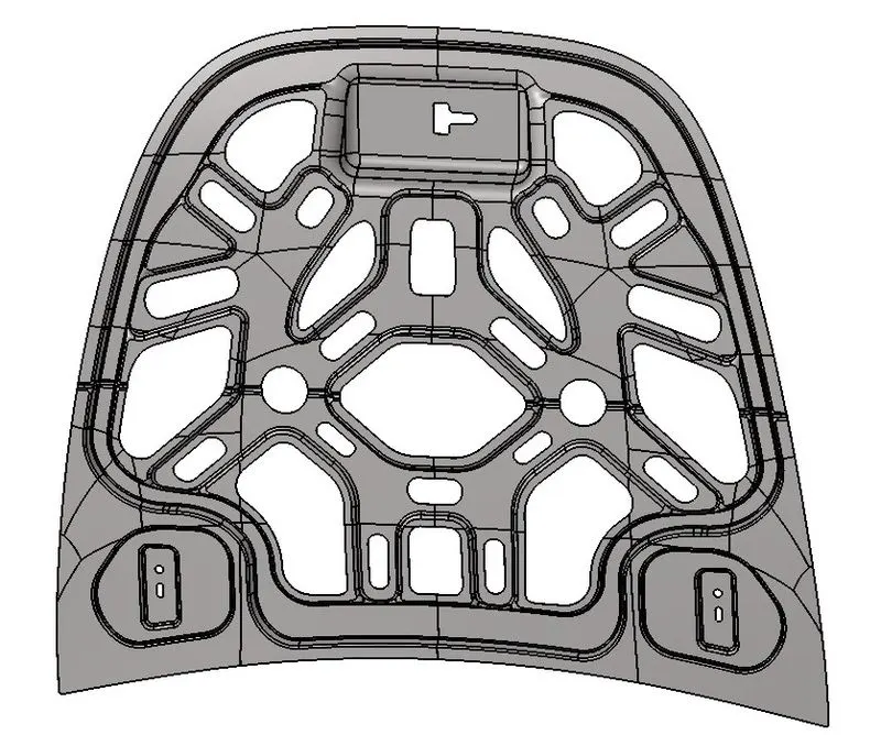
- Midsurface
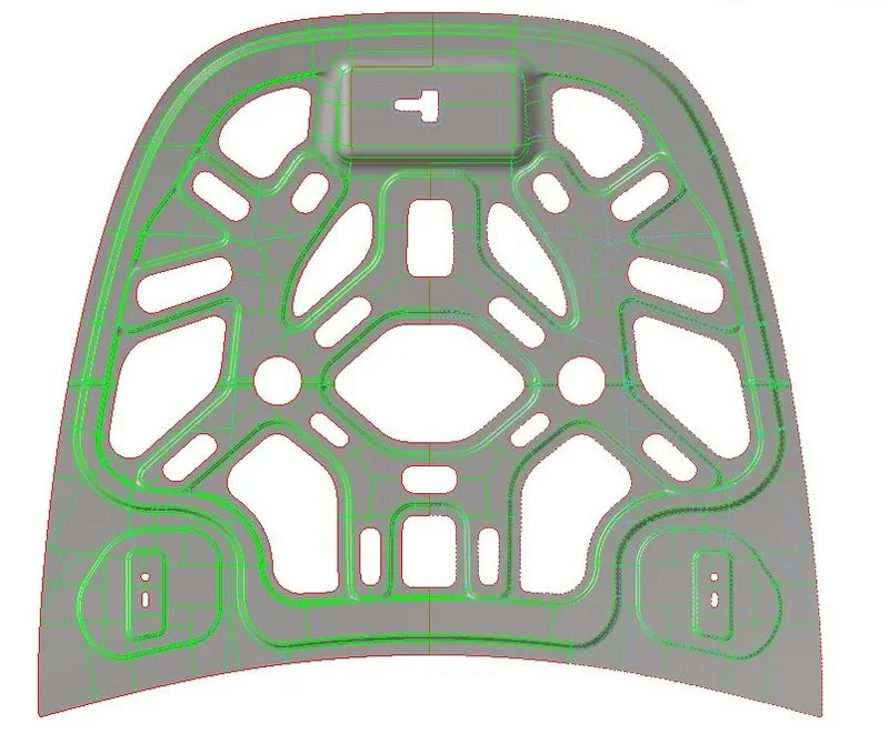
- Meshed component
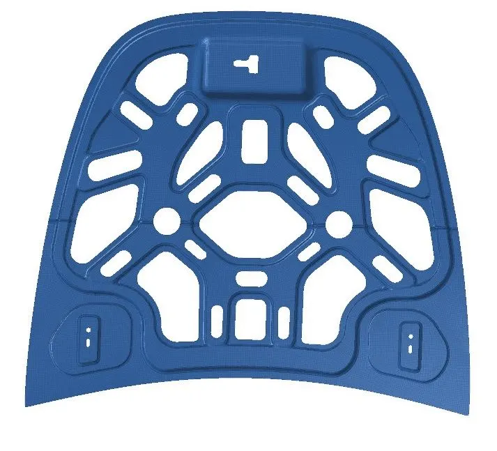
- Quality Index
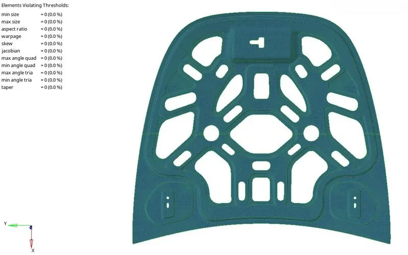
(2). Outer Body
- Original Component
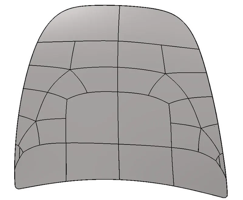
- Midsurface
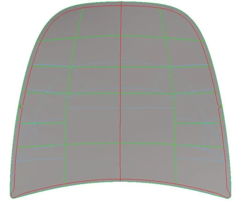
- Meshed component
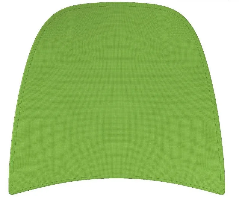
- Quality Index
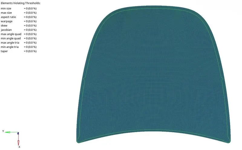
(3). Hinge Body 1
- Original Component
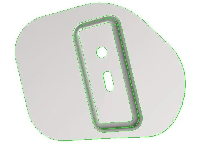
- Midsurface
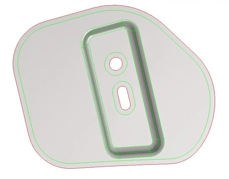
- Meshed component
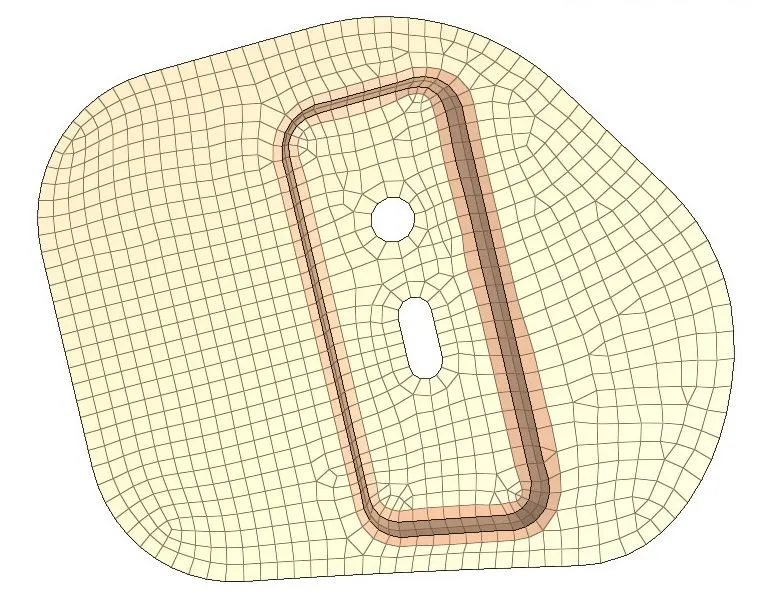
- Quality Index
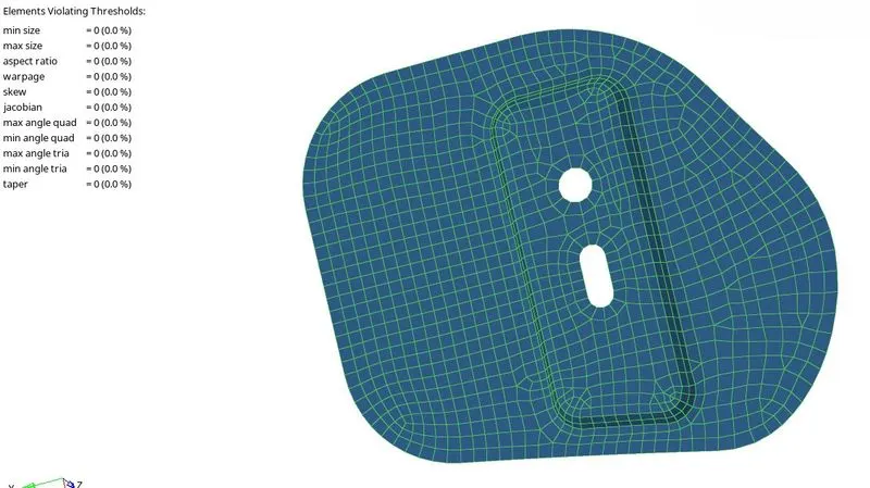
(4). Hinge Body 2
- Original Component
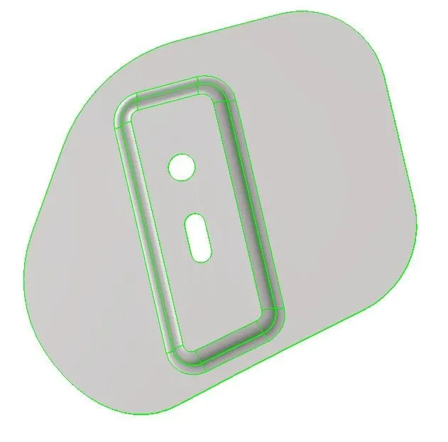
- Midsurface
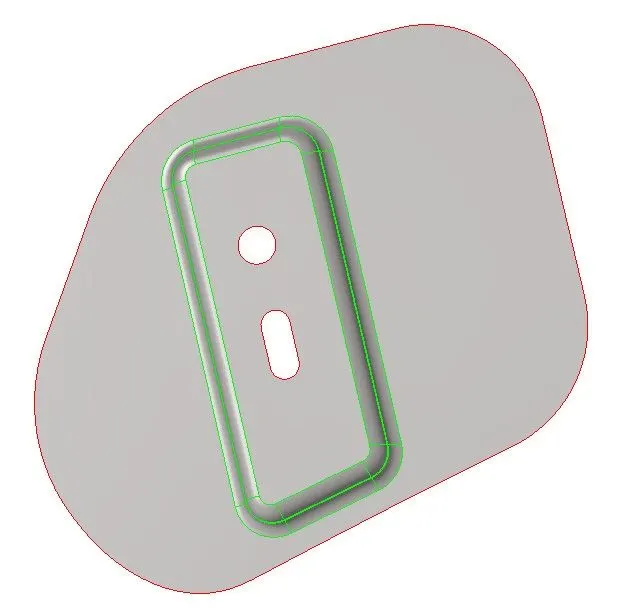
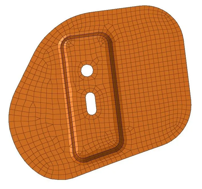
- Meshed component
- Quality Index
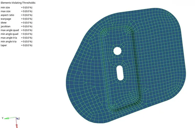
(5). Latch Body
- Original Component
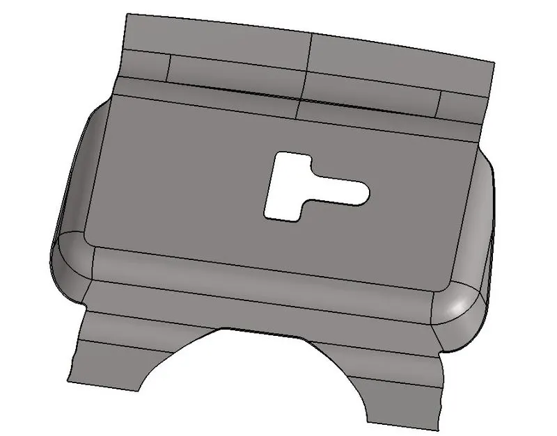
- Midsurface
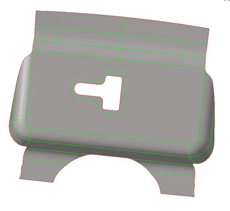
- Meshed component
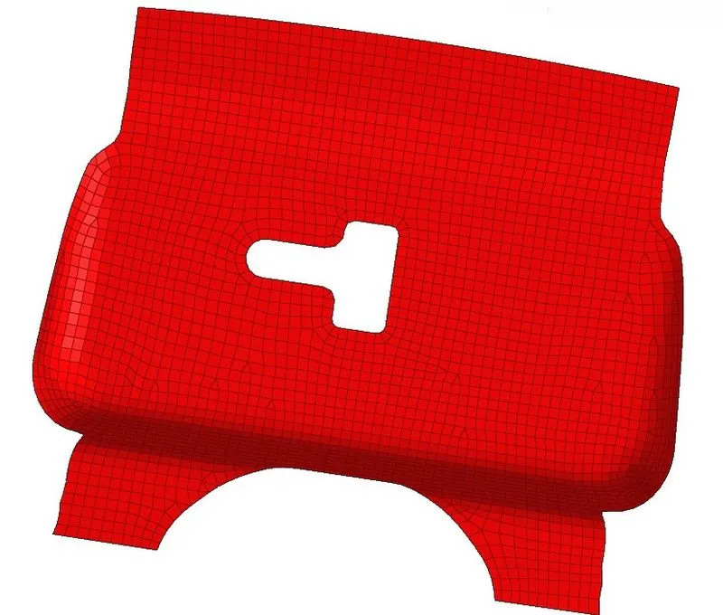
- Quality Index
(6).Thickness Provided to Meshed Surface
(7).Model Tree
LEARNINGS:
- Meshing components according to quality index.
- Quality index cleanup tools
- The mesh should look smooth and regular.
- Use the simplest element type suitable for the component.
- To keep mesh uncertainties to a minimum and simple as possible.
- Try to avoid opposite tria elements in components.
- If a component is converging from either side, tries occur.
- Organising components, creating mid surface,mask,duplicating,reflecting surface and elements, etc.
- Creating property to assign thickness.
- Assigning thickness to the meshed component.