Preprocessing (Meshing) the Car Hood within given quality criteria Using Hypermesh by Altair
Objective: To Mesh the Hood component within the quality criteria and proper mesh flow.
Here we have a sheet metal design so a 2D mesh is performed with mixed element shape.
What is Sheet metal?
Component with thickness less than 6mm is considered as Sheet metal.
Why 2D mesh?
When the two dimensions of the component are very large than the third dimension 2D mesh is preferred, the thickness can be assigned to it as the third dimension.
Why mixed element?
Since the shape of the model is complex and with a lot of convergence and divergence in it, the mixed mesh will give a homogenous mesh pattern.
Procedure:
Step1: Import the .STEP geometry file from import solver deck. (refer figure 1)
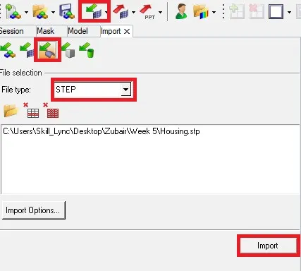
Figure 1.
Step 2: Switch to BY 2D TOPO from GEOMETRY COLOR MODE, which is in Visualization Tab. As shown below. (refer figure 2)

Figure 2 .
Step 3: For ease of topology repair, I used the Visualization tool at visualize tab to check and uncheck the visibility of free, shared suppressed edges, non-manifold lines and that makes it easy to detect the geometry. as shown below. (refer figure 3)
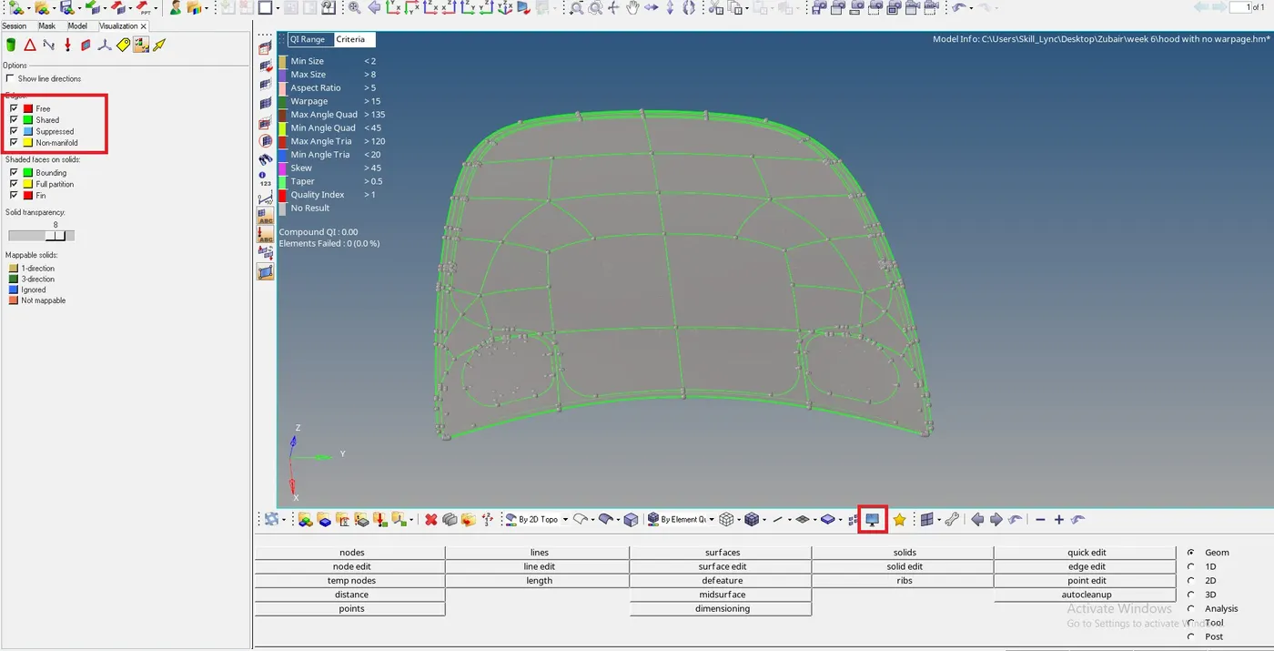
Figure 3
Step 4: Inspect for the bad geometry. and look for the edges. If there is a red edge in between the surface then it means there is a gap or surface missing.
Step 5: I deleted the solids from the model, as I had to perform only 2D mesh and not 3D. (refer figure 4)
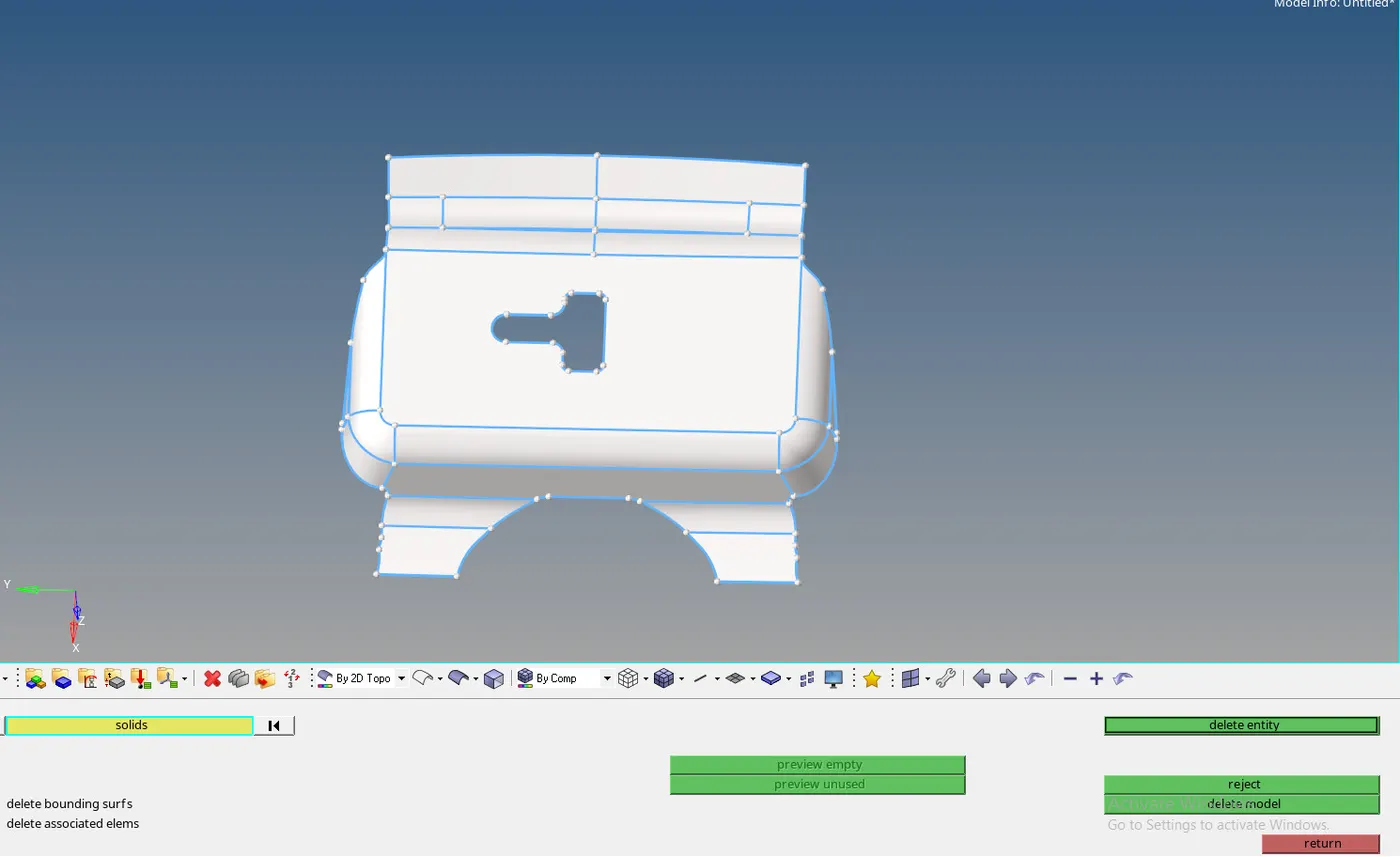
Figure 4.
Step 6: Here I Extracted mid surface for the LATCH component, and renamed the mid surface.
step 7: In the tab menu, I created a new component, and keeping the new component as current with visibility on for HINGE, I extracted mid surface.
Step 8: From TOOL>ORGANZE> select SURFACE and MOVE. It will be then moved to the new component. Rename it as HINGE_MID. Delete the empty mid-surface component. (refer figure 5)

Figure 5.
Step 9: Similarly I Repeated steps from 5 and extracted mid surface INNER PANEL and OUTER PANEL.
(HINT: I didn't extract HINGE2 as I have symmetric Hinge so I can Reflect the same.
LATCH
Step 10: Clean up the geometry. I have few shared edges to be TOGGLED up and I can DEFEATURE in the edge fillet option. (refer figure 6)
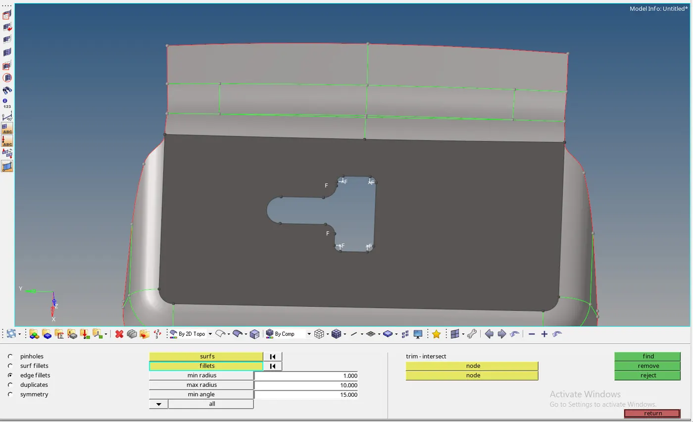
Figure 6.
STEP 11: Once done with the clean up I proceeded with the meshing. For Such rectangular surfaces make sure to enable the FLOW options: ALIGN & SIZE. So it automatically aligns a uniform mesh and avoids tria which in turn saves time. Check the link opposite edges with AR and make it Auto so it sets the aspect ratio automatically to the linked edges. (refer figure 7)
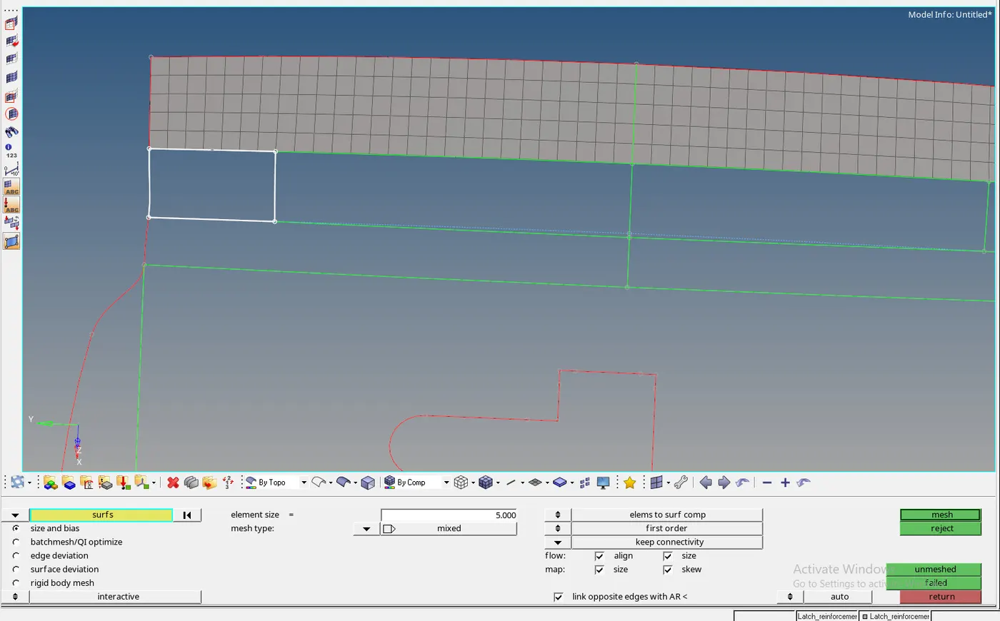
Figure 7.
STEP 12: Solving narrow surface edges helps reduce tria and prevents form element fail as Skewness and minimum length. (refer Figure 8 a &Figure 8 b)
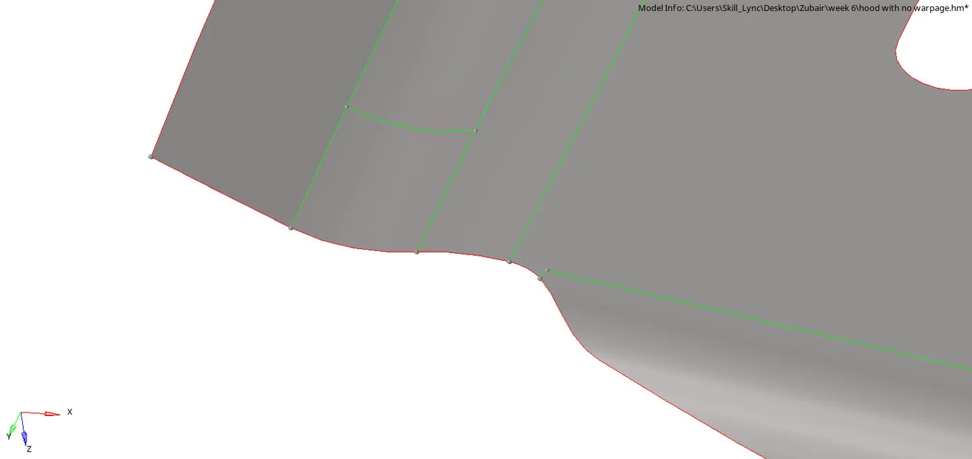
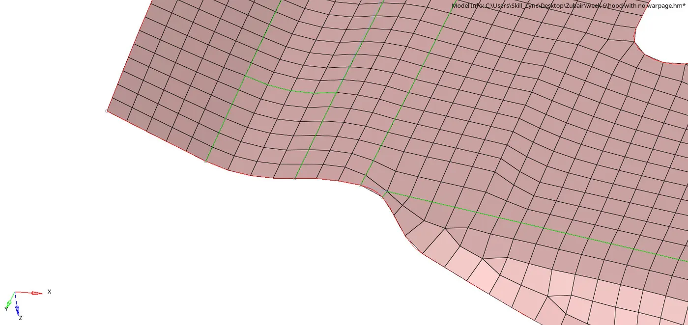
Figure 8(a). Figure 8(b).
HINGE
STEP 13: I Made the HINGE1 as the current component. Looking for geometry and I found uneven-shaped geometry. So to get good mesh flow and reduced trais I divided it into parts. (refer figure 9) (Strategy to get better mesh flow)
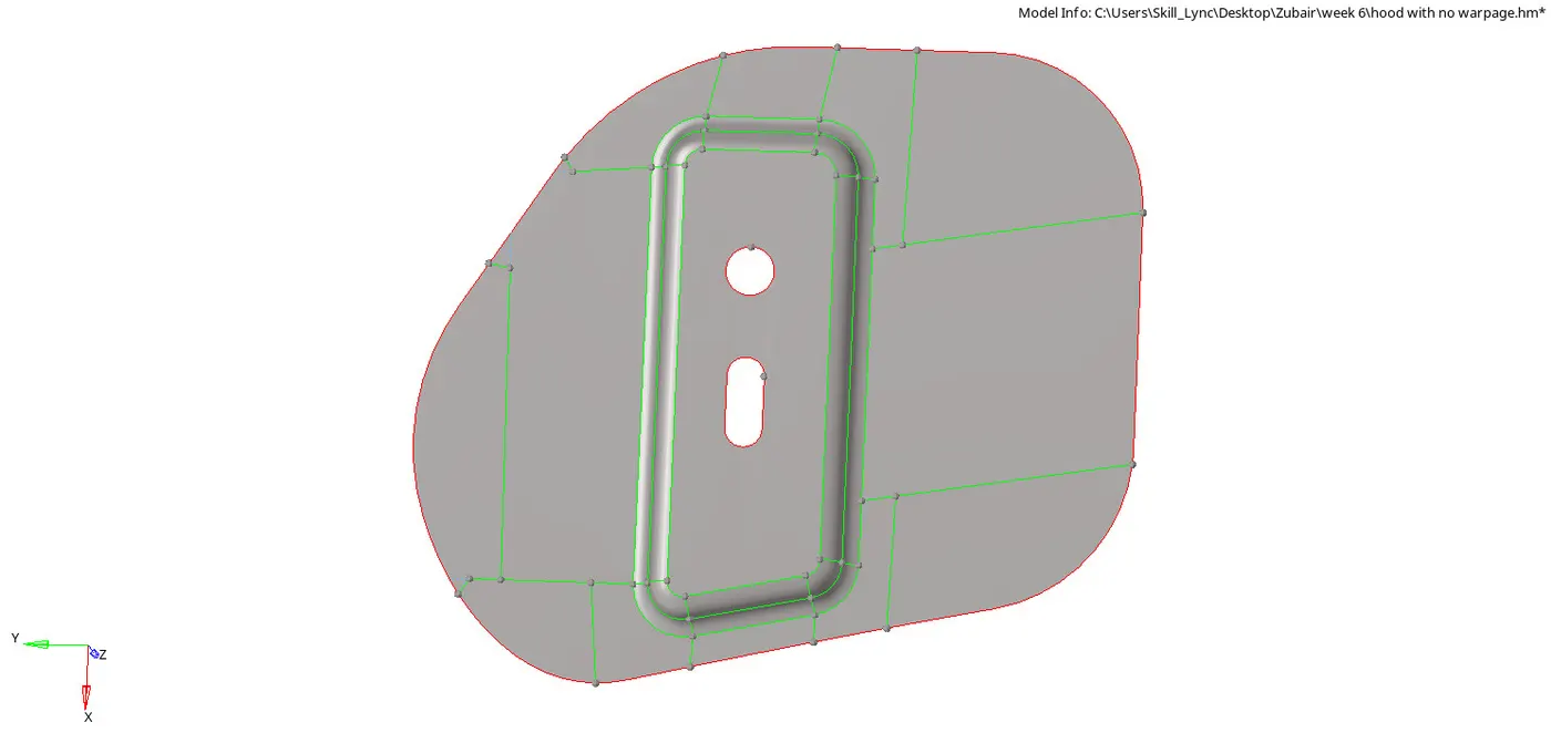
Figure 9.
Step 14: I Started meshing from the complex surface and started from the top (near holes) so that trias and number of nodes can be managed as I mesh towards the free edges. (Strategy to get better mesh flow)
For the elements failing try element optimize to solve. If it doesn't solve try remeshing. (refer figure 10)
- Do smooth opertation on elements after meshing. (Strategy to get better mesh flow)
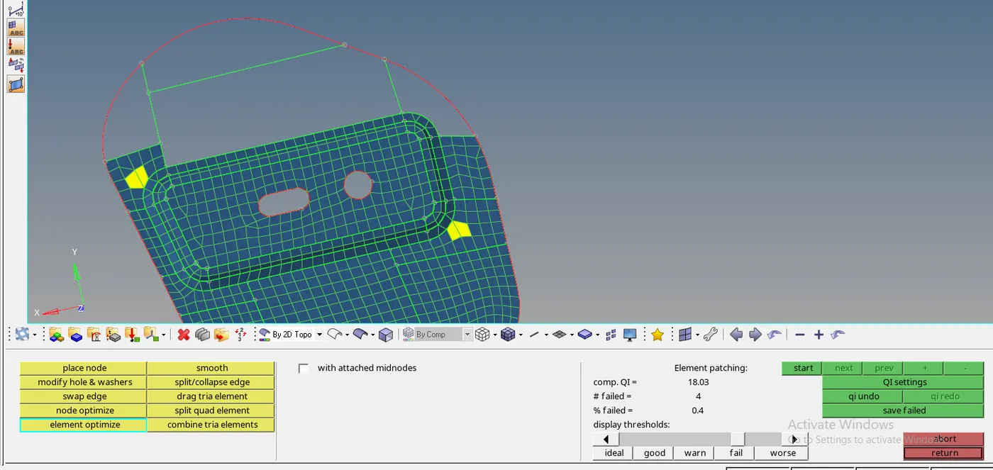
Figure 10.
OUTER PANEL
STEP 15: In this part, I have surface with curve-like fillets which are called HEMMING. Hemming is a forming operation in which the edges of the sheet are folded or folded over another part in order to achieve a tight fit.
since the distance of hemming is less than the desired quality I toggled the other lines and then defeature it. (refer Figure 11a & Figure 11 b) (Strategy to get better mesh flow within quality criteria)
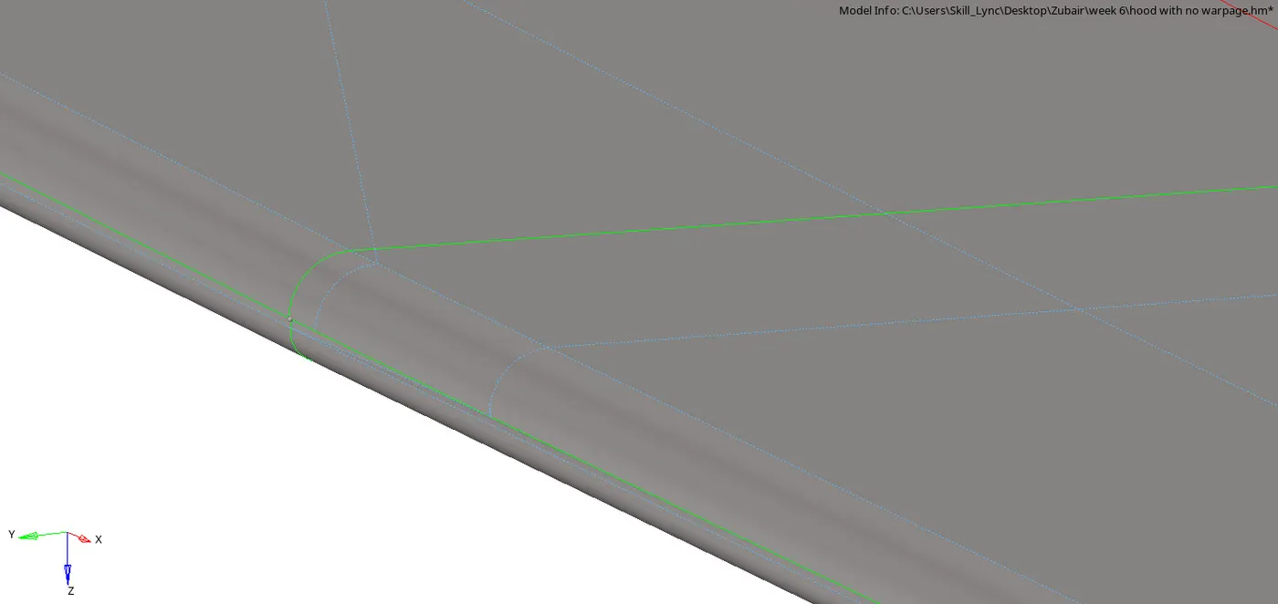
Figure 11 (a)
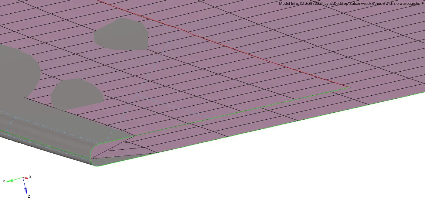
Figure 11(b).
Step16: Since the Outer Part is symmetrical I deleted half of the part and reflected it after meshing. (refer figure 12)
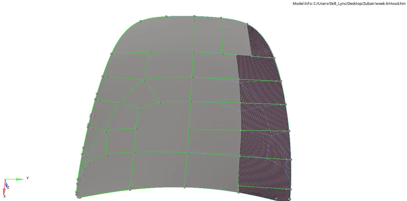
Figure 12.
STEP 17: Once half of the part has meshed with all the desired quality and mesh I reflected it. While reflecting I need to reflect elements and surface as well. TOOL>REFLECT. (refer Figure 13a & Figure 13b)

Figure 13 (a)

Figure 13(b).
From options select elements and select DISPLAYED and again from element options select DUPLICATE> CURRENT COMPONENT. Since my meshed part is symmetrical and I need to reflect it on Y-axis. Select the base point at the corner (from the middle of the whole component) left side of the meshed component and select REFLECT. Similarly, I did the same procedure to reflect the Surface.
Step 18: Once after reflecting, Connect the nodes of elements at the axis of reflection. To give equivalence, select TOOL> EDGES. Select elements by Displayed and select FIND EDGES.
Here after switching off the mesh and surface visibility I checked for any non connected element nodes. If there is any connectivity issue I can equivalance the nodes by selecting elements and selecting the PREVIEW EQUIVALANCE tool.
The nodes with connectivity issues are being highlighted now keepin tolerance to 1 or 2 depending on the mesh quality criteria select EQUIVALENCE. (refer figure 14)

Figure 14.
INNER PANEL
Step 19: Make this component as current and hide or disable the visibility of the rest of the parts.
Step 20: Since after observing carefully I found it symmetrical, so I can delete half of the surface and reflect it later after meshing.
Step 21: Clean up the geometry. Toggle the lines that have a distance that can fail for minimum element length. Divide the big parts into small to get the best mesh with the least trias. (refer figure 15)
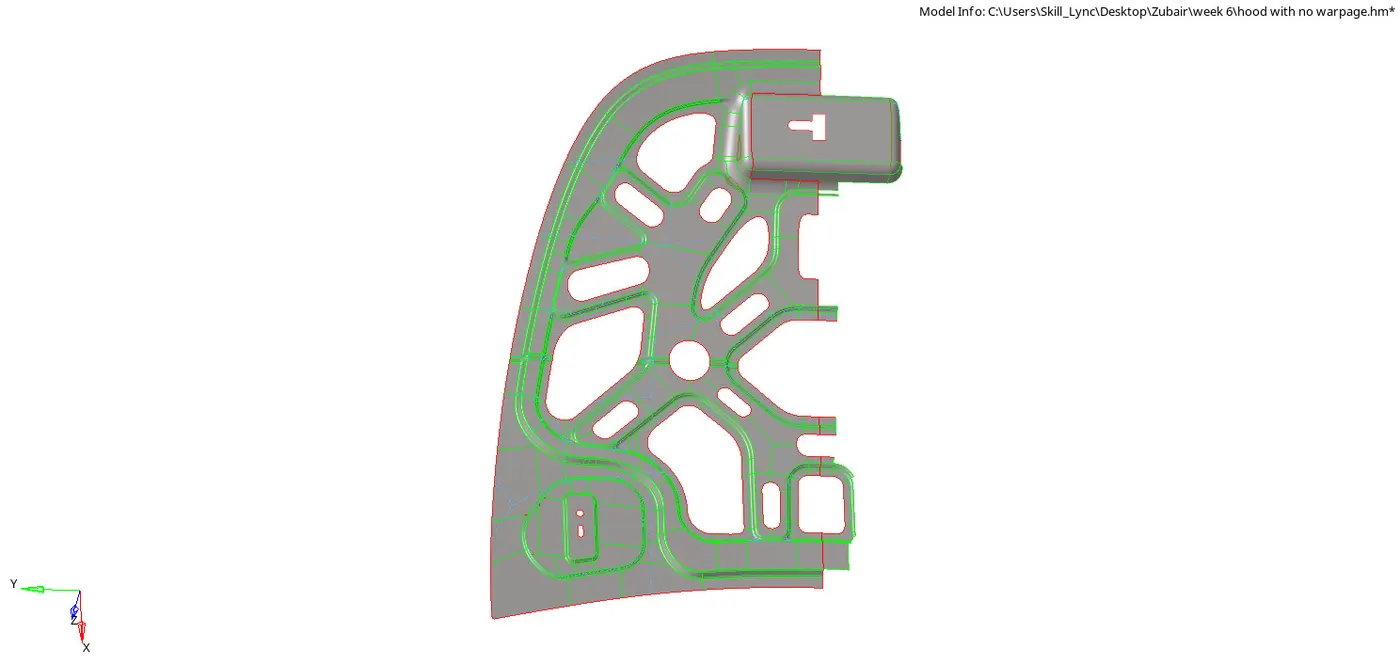
Figure 15.
(The Latch part in this is not symmetrical hence not deleting it. )
STEP 22: Mesh the component and do the same procedure till reflecting and equalizing the nodes.
(I Made sure to check for duplicates after reflecting) From TOOL>CHECK ELEMENTS and select duplicates after equivalencing. The information bar will shoe in left bottom corner if any duplicates available.
CHECKS:
Tria concentration: As tria being stiff element it is advised to avoid regions with trai concentration. And one method I used to detect trai concentration is changing element color mode to by config which shows trai in blue colour and rest of quads in pink colour so it gets easy to identify tria concentration and remesh that part or area.
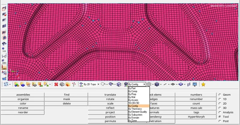
Checking normals : At last check for element normals. Go to Tool> normals. Setlect elements and select display. If all the elements on one side do not have same orientation (colour) then adjust them. Select Adjust. it automatically adjusts the normals. If it dosent there is a chance of duplicate elements.
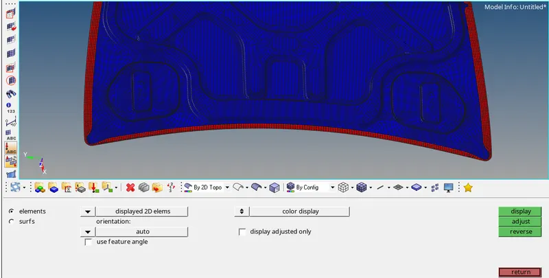
Result: A proper mid surface with geometry cleaned and meshed with zero elements failing for quality.
FINAL MODEL IMAGES:
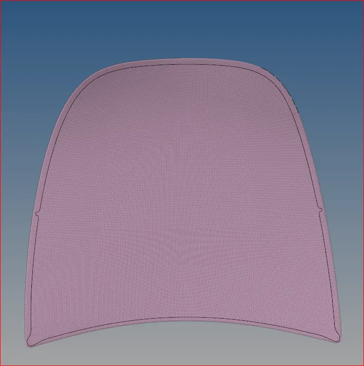
Outer Hood.
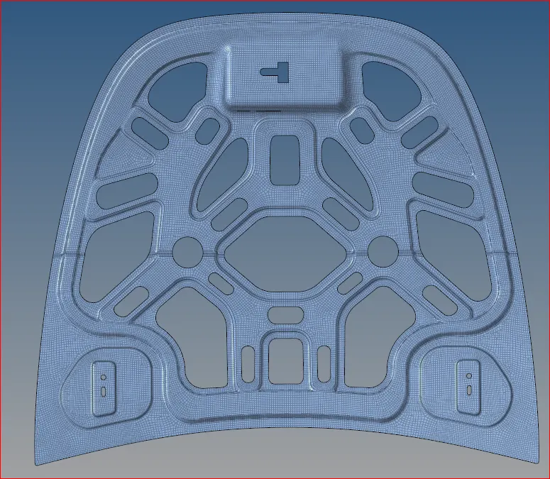
Inner Hood.

Right Hinge
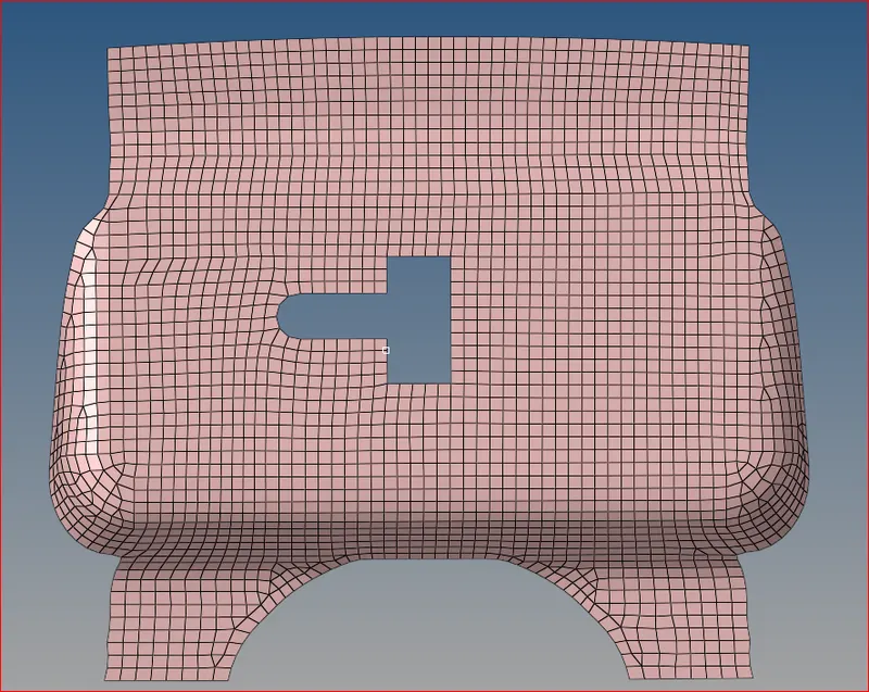
Latch.
Learning outcomes:
- Topology clean up.
- Midsurface extration
- Working with Trias.
- Working with Quality criteria.
- Working with Feature capturing.
- Maintaining proper Mesh flow.
- Checking normals.