Side pole car BIW crash analysis under FMVSS using Hypermesh & Radioss
OBJECTIVE:To Study the behaviour of Side Impact with given loading conditions and boundary conditions. That includes sectional forces at various parts, intrusions at passenger compartment.
(Since due to limitiation of 100k nodes in Student edition calculation is done on BIW model till B-pillar with 99084 nodes in total.)
ABSTRACT:
These tests are performed to simulate crashes that usually take place in intersections. Engineers performing these tests usually use two vehicles or a vehicle being hit by a steel structure with wheels that simulates another vehicle. The test is used to determine how efficient crumple zones are, how large is the deformation and how many elements enter the “survival cell”. Given the mechanics of this crash, it is one of the most dangerous ones and most likely to produce serious injuries or even death, because the side of the car doesn’t have a crumple zone big enough to absorb all the impact energy. That’s why car manufacturers went through a lot to equip their cars with side airbags, one of the most important safety features a car can get because it protects the upper torso and prevents the head from passing through the window.
Car to Car Side Impact Test – The vehicle is hit on the driver’s side by a mobile deformable barrier traveling at 50 km/h (31 mph). An important part of the test is evaluating how the car side intrudes and almost all cars going through this test are equipped with side airbags.
Pole Side Impact Test – The test involves a vehicle being projected sideways into a rigid pole at 29 km/h (18 mph). The pole’s diameter is 254 mm (10 inches) and it seriously damages the car.
In side pole impact collision cases, the load transfer from pole to the vehicle side structure, and then structure deforms and it contact with dummy pelvis location. Due to this structure to pelvis contact the load has transferred to the occupant. As only a very small crumble zone is available during a side pole impact, so we have to ensure that the impact forces are distributed over a wide area. The B-Pillars and side members along the vehicles flanks are mainly responsible for this. Both components are partly manufactured from ultra-high strength, hot formed high steel. The impact forces are transferred from B Pillar to the opposite side of the vehicle first and foremost via the transversely rigid seat and the center console. A further load dissipation path runs from the base of the B pillar to cross member under the seat and transmission tunnel braces. Asper base line study, identified the important load transfer path members are B-Pillar and its reinforcements, Roof bows, Sill, Transfers cross members. These parts stiffness increased by the way of design changes and material grade up.
"Pole" means a fixed rigid vertically oriented metal structure with a
continuous outer cross section diameter of 254 mm ± 6 mm, beginning no
more than 102 mm above the lowest point of the tyres on the impact side of
the vehicle in the laden attitude, and extending at least above the highest
point of the roof of the test vehicle.
ANALYSIS SETUP:
(Operations can be done in Hypermesh and in Hypercrash as well.)
1. Check unit system.
In BEGIN card, we can see the unit system we'll be considering throughout.
(it is important as same numbers with different unit system results in wrong calculations.)
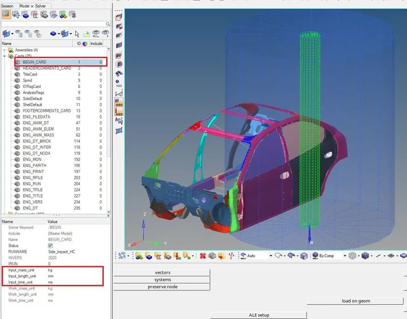
or can be checked or changed fron Engine File
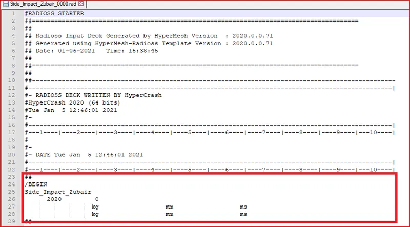
Here we will follow [Kg mm ms].
2. Use added masses to reach target weight 700kg while getting CG about the required range. (Done in Hypercrash)
- Browser > Added Masses > create new object
Type=1 Mass is distributed to each node of the node group (to randomly select nodes in some area)
Type=4 Final mass is distributed on part group. (to assign it to whole part)
- Add mass to target weight 700 kg.
CG matters most during crash. CG, during a crash deccides whether your car is going to roll forward or yaw.vehicles with higher centers of gravity are at a greater risk of rollovers even when another car is not involved. The risk is even higher when these types of vehicles travel at high speeds. like Bus.
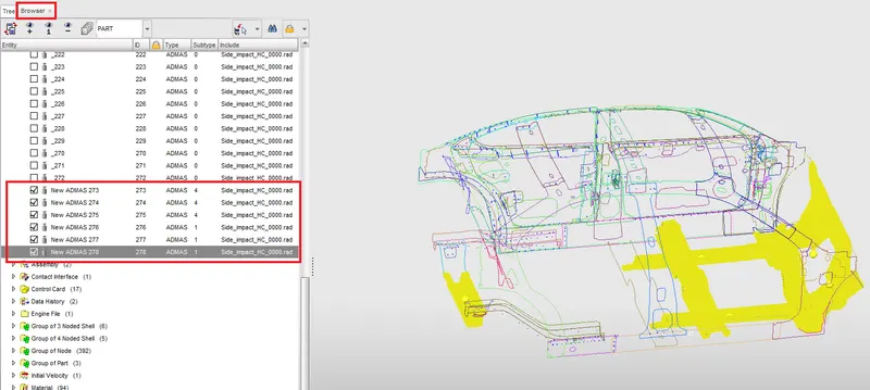
[Note: while adding mass check the unit Ton or kg, as it will change whole results.]
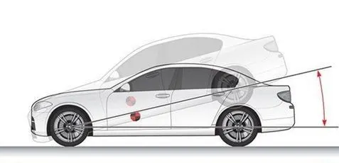
Usually Ideal place of Cg in Car is under driver seat. As shown below.
3. Create appropriate interface ,friction 0.2 and recommended parameters.
(interface can be made in hypermesh also.)
The more interfaces we create more time will it take to compute. so no unnecessory interface should be ctreated.
Here we will create self impact contact interface as during front crach there are high chances of parts self impacting.
[Process :in Browser tab right click Create new> A-C > contact interface>Multi usage (type 7) ]
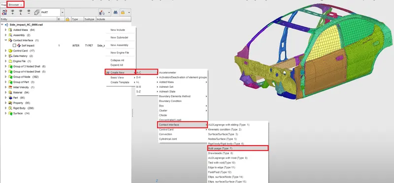
Type 7 interface:
(what is type 7 interface? )
It is a general purpose interface and can simulate impact between a set of nodes and master surface. Non oriented and slave nodes can belong to same master surface, hence self impact possible with type 7.
Recomended parameters
- Remove all intersectons to get physical results and to avoid solver error.
- Igap=2 Set varialble gap to take into account the true distance between parts
- Gapmin = 0.5 Minimum thickness of the model to avoid errors.
- Inacti=6 Remove initial penetrations where possible else where. reduce to lessthn 30% of the defined gap value.
- Istiff= 4 Stiffness of interface based on the surface of master & slave.
-Stmin=1 Specify a minimum stiffness in the contact to avoid too soft contact.
- Idel=2 Remove slave nodes sfrom contact because of element deletion.
- Iform=2 Sliding forces are computed using stffness parameters of interface.
4. Make sure of no penetrations and intersection.:
Quality> Check all solver contact interfaces.
Here we check penetrations after assigning the Type 7 properties as we define gap minimum which is used to check penetrations.
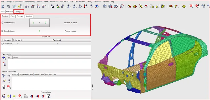
[ Exporting the file and continuing in Hypermesh.]
5. Create rigid wall with friction 0.1.
What is rigid wall?
Rigid Walls allow for an easy way to define an interface between a rigid surface and nodes of a
deformable body. A rigid wall is a nodal constraint applied to a set of slave nodes in order to
avoid the node penetration to the wall (In this case Cylindrical pole). If contact is detected, then the slave
node acceleration and velocity are modified.
The slave nodes to a rigid wall can be defined as a group of nodes and/or as nodes initially at a
distance less than the distance (Dsearch) from the rigid wall
• Each wall can be fixed (point M) or moving (node N)
• A Rigid Wall is a Kinematic Condition
• If a slave node penetrates the rigid wall surface a new velocity is computed
• From this velocity, the impulse and rigid wall force are determined
Rigid Walls /RWALL: Limitations
Some limitations with Rigid Walls
• Can only be fixed or have initial velocity – may want to move rigid object with an imposed
displacement function
• Can result in Incompatible Kinematic Condition – a result of nodes belonging to another
kinematic condition and the rigid wall
(A part of cylindrical rigid wall can also be used as speed breaker to study behaviour of car with tyres as slave node during contact )
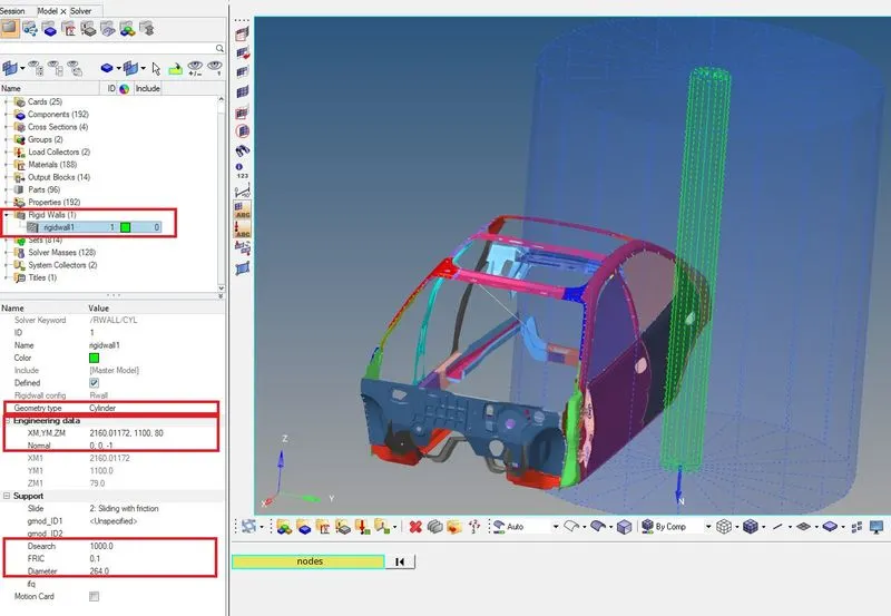
On B-pillar, create tempnodes and translate a duplicate of that node with 100 magnitude in Y direction.
Now Create Rwall from Model and in the tab Engineering data XM,YM,ZM select the translated node and proceede
in Normal select Z axis and proceede.
Geometry type: Cylinder.
In Support > Slide> 2: Sliding with friction.
in FRIC add 0.1.
Give dsearch as 1000.
What is Dsearch?
It is the search tolerance by master node for slave node. Node withing the range will follow master. A slave which is not in search tolerance may get deleted.
6. Initial velocity 35 mph.
In solver tab right click and select create> Boundary conditions >INIVEL
New INIVEL will be created. in grnd_ID, right click and select create & edit and select nodes of car body from extended entity selection displayed.
converting 35 miles per hour to m/s (i.e., 15.646 m/s or mm/ms).
In velocity component We give 0,15.64,0 with respect to Y axis and 0 velocity in X and Z derection.
7. Use model checker to ensure good quality.
Go to Tools in menu tab and from drop down list select Model checker> Radioss.
Model checker tab will open up. Run checke. Errors and Warning will be shown in the tab.
Note No more than 4-5 Warning should exist and only one those one which can be ignored.
8. Time-step :0.5 to 0.1 microseconds.
In model > Control cards Check
ENG_DT_NODA
ENG_DT_BRICK
ENG_DT_INTER
Change Tmin value to .001 (The actual value is supposed to be 0.0001 but to get simulations quickers just to check with the results we'll be running at 0.001
9. Run 80 ms.
In Model> Control cards> ENG_RUN
Give Tstop as 80.
10. Creating Sections. What are Sections?
Sectional force in the cross member.
- CH-CBN-SEAT-REINF-FT : Front Rail
- CH-RAILS-U-MID : Rear rail
To create Section at Front Rail, isolate parts that are going to be assigned under that section. one way is to Call display panel (shortcut D) and select parts and reverse display.
Now in Solver tab Create Local Moving frame. Right click CREATE>FRAME>MOV
- Select Origin node, Z-axis in direction toward rigid wall, and select Y node.
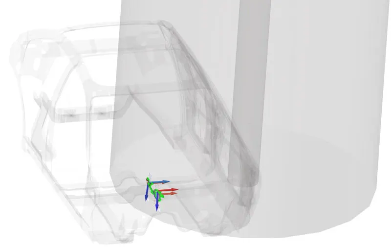
Create Section
- Right click ar solver and select Create > SECT > SECT.
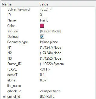
Geometry type: infinite plane
Select N1, N2, N3 same nodes as selected for frame
Frame_ID : select the Frame arrow we created.
deltaT : 0.1 (it is time step for saving the data)
alpha : 0.67 (it is coefficient for filtering, it should be less than 1)
gr_shelid: select the elements around the section (atleast 2 rows on bothsides of the section)
Do same for the rest of sections
11. Intrusions at B pillar,hinge pillar and fuel tank region.Provide recommendation on what can help to reduce Fuel tank intrusion.
What are intrusions
Intrusion results when the energy of the crash exceeds the strength of the vehicle frame, resulting in a violation of the occupant compartment. Injury may then occur either from direct contact with the vehicle structure, or passenger movement as a result of the acceleration imparted to the occupant from the vehicle.
intrusions in EV
side impacts are always fatal because of the limited deformation space to absorb impact energy. This precondition, combined with high intrusion velocities, results in a short time between the beginning of the collision and the moment when the intruding door panel contacts the power battery. In such cases, short-circuit phenomenon may occur within the battery system, which can easily evolve into more serious incidents such as thermal runaway and even flaming and explosion, owing to the use of volatile materials such as lithium metal and flammable solvents. Aroud 25-35mm is the maximum allowable intrusions in EV (depends on design, location of battery and distance od battery from door farme.)
Process:
- CH-CBN-SEAT-REINF-FT : Front rail : 123322-124316
- CH-RAILS-U-MID : Rear rail : 123280-124274
- CH-CBN-SIDE-MID-L: Rocker near fuel tank : 123161-124155
Create temp nodes at the points given by id. From 1D> Spring, Spring2 create spring by selecting 2 nodes.
Here We are taking spring element to calculate the change in distance between two nodes and since it is spring it should have some property, to avoid error we assign negligible mass of 0.001 and negligible stiffness of 0.001
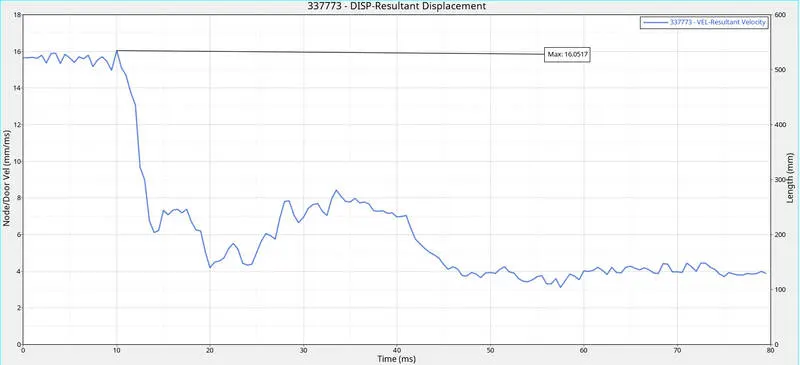
12. Peak velocity of inner node of the door.
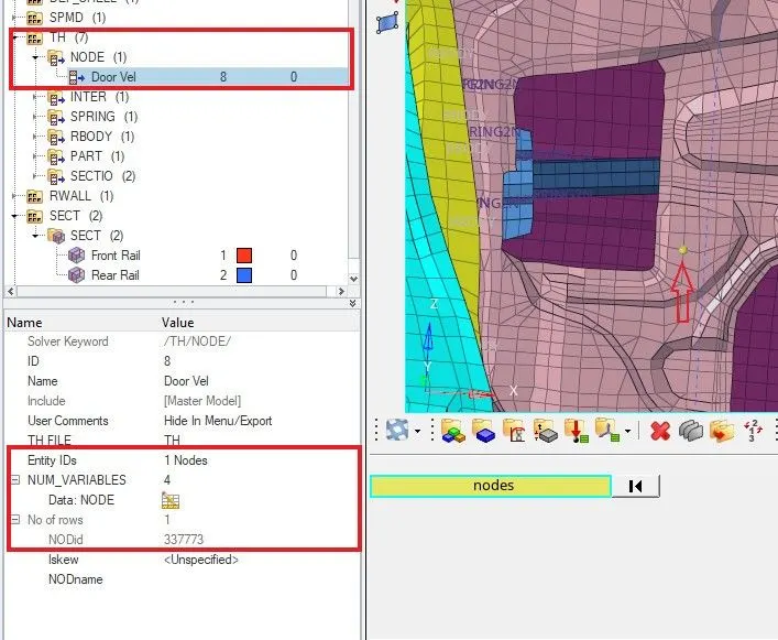
A Time history output for a node no 337773 on front passenger door is requested to check variation in velocity.
In solver in TH > create > Node> Select node and in NUM_VARIABLES add Total resultant velocity.
13. Correct rigid bodies if any issues.
Make connections to parts which are not connected to any other part. to check unconnected parts
Create new components as Rigids and Go to 1D and select rigids make it continuous nd multiple nodes selections. select two node of different part to establish a rigid connection.
RESULTS
SECTION FORCE
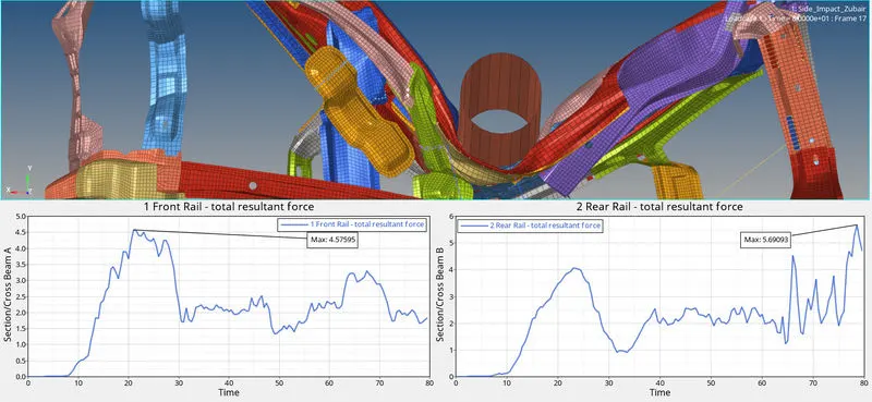
Here, we see
- Total resultant forces in A pillar Left are slightly greater than Right.
- Total resultant forces in Shotgun Left jumps greater than Right.
this is because the shape of CH-RAILS-FT-L-O and CH-RAILS-FT-R-O, Due to such shape L part deforms more henge generating more force than right side.
INTRUSION
- CH-CBN-SEAT-REINF-FT : Front rail : 9900039
- CH-RAILS-U-MID : Rear rail : 9900038
- CH-CBN-SIDE-MID-L: Rocker near fuel tank : 9900037
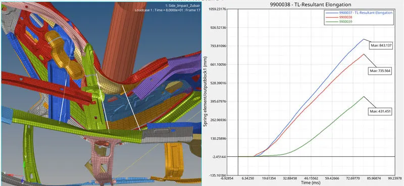
Here Spring no. 9900038 being the one below B-pillar and near to rigid wall has relatively less intrusion than 9900037 due to the shape of sturucture and its deformation as evident above.
Spring 9900039 being far from rigid pole hence has least intrusion of three.
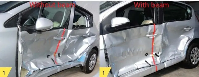
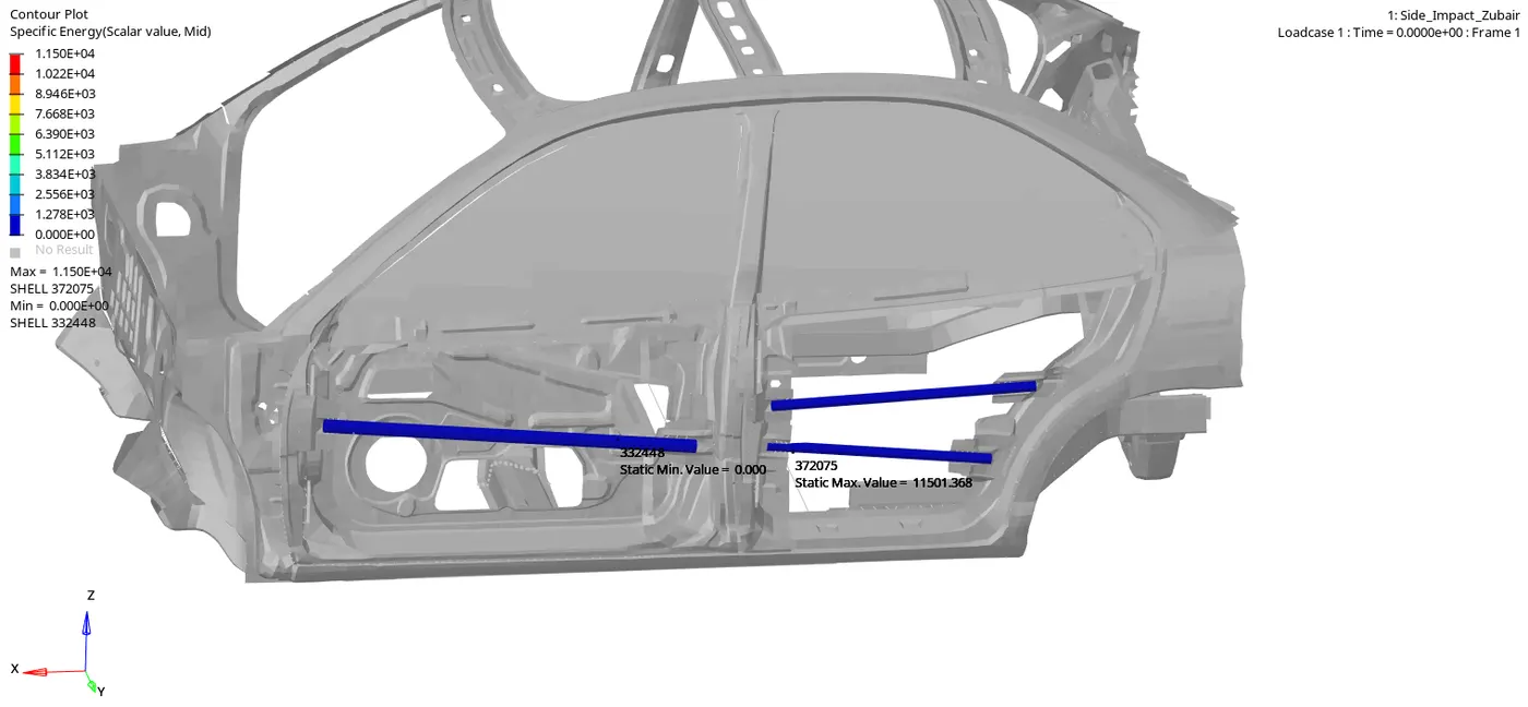
Since we considered
Anti-intrusion bars:
Load Transfer Path:
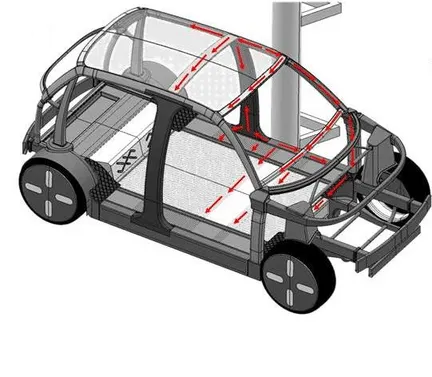
The entire side frame such as A- and C-pillars act to support the load transfer in the plane. After the initial load has been transferred away from the point of impact it is
transferred away from the impact side to the opposite face, for example over the roof and forward bulk head. The goal of this concept is to maintain the survival space of the occupants until curtains and side airbags are deployed and to keep the maximum intrusions into the passenger cell below a maximum value throughout the entire crash.
Peak velocity of inner node of the door.
As per law of inertia when the Car hits pole, the frontal and rear part of car tends to continue to be in motion and due to vibrations addingon to it we can se the velocity of node on door touches peak at 16.05mm/ms which initilly had velocity of 15.64mm/ms before hitting pole.
As per FMVSS 214 standards, During the Crash the Impact value on Dummies placed inside, injury limit is calculated and based on that the vehicle passes or fails the safety test.
| Injury Criteria | Max. Allowable IARV |
Measured Value |
Pass/Fail |
| HIC | 1000 | ||
| Upper Rib Deflection (mm) | 44mm | ||
| Mid. Rib Deflection (mm) | 44mm | ||
| Lower Rib Deflection (mm) | 44mm | ||
| Abdominal Load (front) (N) | |||
| Abdominal Load (mid) (N) | |||
| Abdominal Load (rear) (N) | |||
| Sum of Abdomen Forces (N) | 2.5 kN | ||
| Pubic Symphysis (N) | 6 kN |
CONCLUSION:
Since it is not a full model due to lmitations it is failing for safety as there are large intrusions on side and this may cause injuries to occupants.