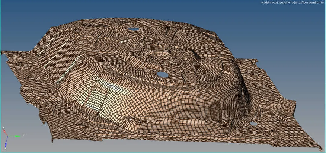
Preprocessing (Meshing) car spare-wheel floor panel using Hypermesh by Altair.
Abstract
The spare-wheel well is a common component on most passenger vehicles with a trunk or rear hatch (back door). This round or square pan is mounted into the trunk opening, where it holds an extra wheel and jack. Traditionally produced in stamped steel, and more recently in aluminum, this spare wheel well (SWW, also known as a spare wheel baffle) is a large, heavy, tub-like component.
This component must pass a number of tests. Spare-wheel wells mounted into the vehicle must meet impact requirements. The wheel well must stay attached to the vehicle frame after a crash. Impact performance is influenced not only by the structure of the well itself, but also by the amount of energy that is absorbed by the steel or aluminum wheel hub. This test is considered to be the most important requirement for any SWW design to pass. SWW components are also subjected to tests that evaluate resistance to noise/vibration/harshness (NVH), hot and cold climates, flammability, common automotive chemicals, and long-term heat aging and various standard mechanical tests conducted on complete parts for impact, tensile strength, etc
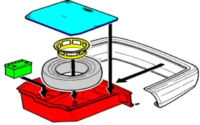
Procedure:
Step1: Import the model file from import solver deck. (refer figure 1)
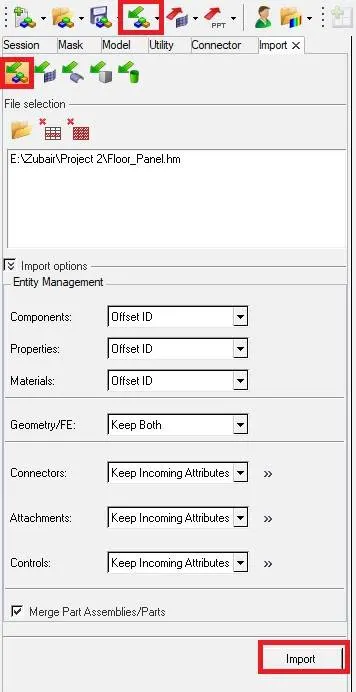
Figure 1 .
Step 2: (Inspect the model ) Switch to BY 2D TOPO from GEOMETRY COLOR MODE, that is in Visualization Tab. As shown below in (refer figure 2)

Figure 2 .
Step 3: After a little inspection we found 20 components, out of which one was main component and other were either part of main component or empty component. So organise it before starting makes easy for geometry cleanup.
- Delete the empty components. go to Delete panel Select Components from drop down menu and select Preview empty. Bottom right corner displyays the the number of entity component. Here ( components are empty. Select Delete entity.
- Check for the remaining components, delete the deformed surface parts that can be re created. Move the rest of the parts to the main component.
Go to Tool > Organize and from dropdown select the surface. Make the main component as current component and in destination component select the main component.Select move. (refer figure 3)
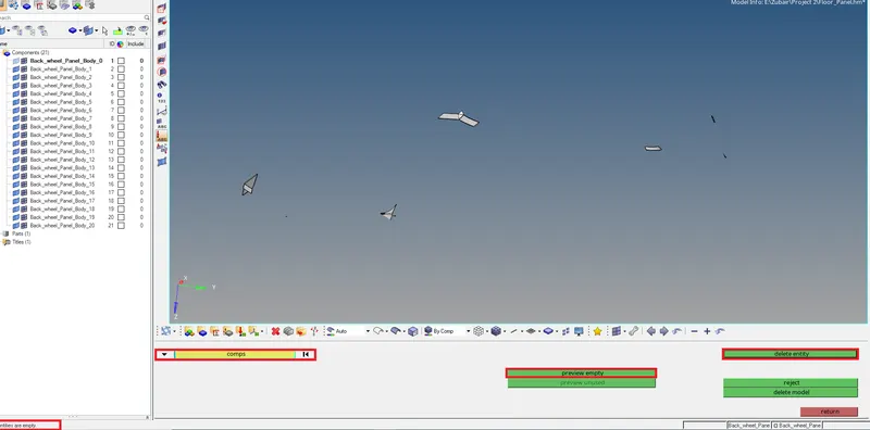
Figure 3.
Step 4 :For ease for topology repair, we can go to Visualization tool at visualize tab. check and uncheck the visibility of free,shared suppresed edges, t- junctions and that makes easy to detect the geometry. as shown below. (refer figure 4). Here we can see Red line as there is a open surface or gap.
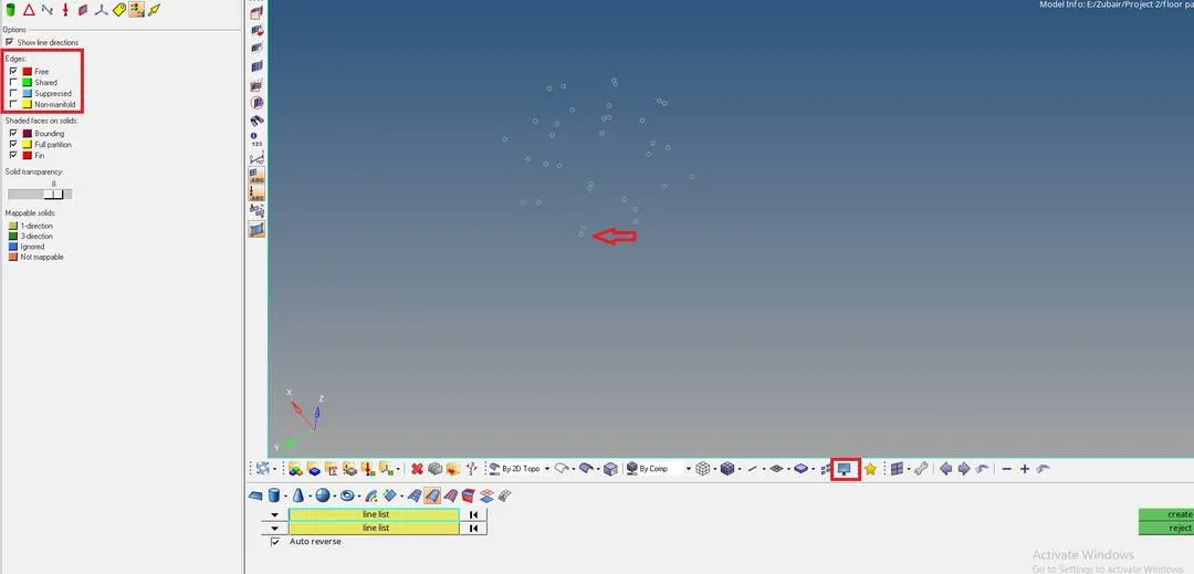
Figure 4.
Step 4: Geometry clean up is the basic step before meshing as it improves the mesh quality. In this Model we have few geometry cleanup to do as shown below
- There are few small pinholes which can't be captured with the quality of minimum element length. Delete such features.
- Figure shows red & yellow lines ( free edges and t junctions which should be green as shared edge)
After Inspecting it by masking the surface, there is a tiny unwanted surface which needs to be deleted to clean this on both the sides. (refer figure 5)
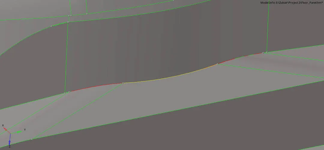
Figure 5 .
- Figure shows duplicate surface as when selected we can see overlapping surface or deformed surfacre.
Mask the top layer of surface . There is deformed surface which has points that can be replaced.
Still it has duplicate surfaces that is obvious since it has yellow edges.
Go to delete panel ( shortcut : f2) from options select surface and select the over lapping surface and delete the surface. (refer figure 6 & 7)
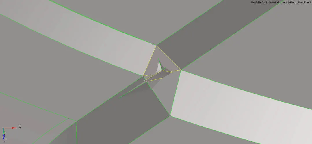
Figure 6 .
- Here we cam fix the deformation just by replacing the point as it is obvious as the green shared edge is diverging to triangle below .
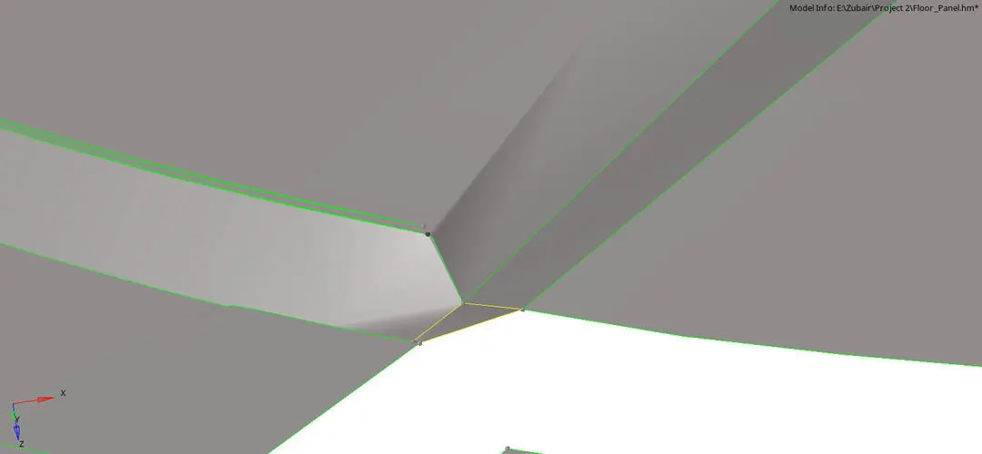
Figure 7.
- Figure shows the pinholes with diameter 2.5 mm which is near to our minimum element length which is 2mm, the elements won't be able to capture the hole properly so we delete the holes from delete panel and then fill the hole. Go to Geom > quick edit (shortcut : f11) and select the filler tool select the hole and toggle the hole surface from toggle tool. (refer figure 8)
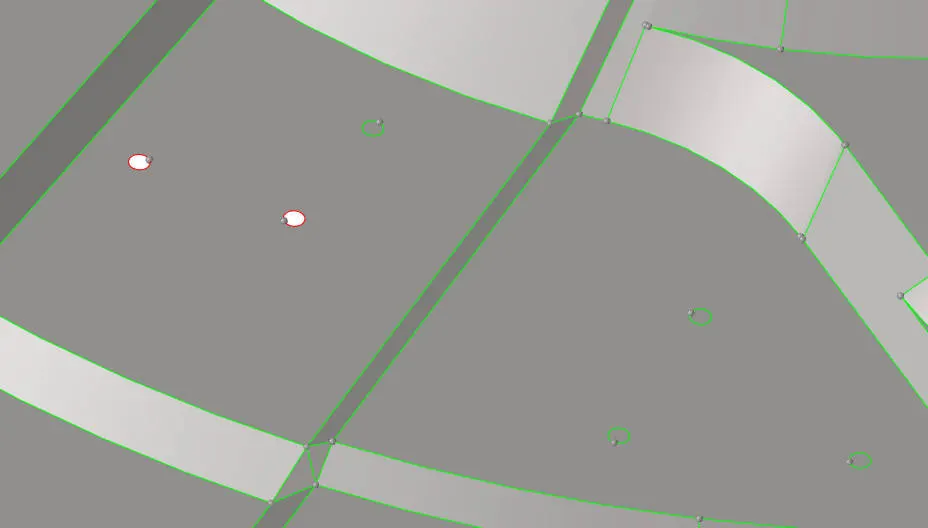
Figure 8.
Step 5: Toggle the unwanted lines which can cause minimum element failure when meshing. to toggle go to Geom > quick edit (shortcut : f11). Create cuts in surface to make rectangular surface where ever possible to get a good mesh flow.
Step 6: Moving to Second major step i.e. Midsurfacing. ( If not turned on turn on the display fixed points options from pannel which makes easy to measure distance from point to point.)
- Check the distance at random points of surfaces. go to Geom > Distance ( shortcut F4) and select two points option.
- Since the thickness is varying between 0.75 and 1.64mm we can take auto midsurface by Offset + plane +sweeps
- Go to Geom> Midsurface. From options select extraction options select Offset + plane +sweeps. Go to Auto extraction , select surfaces and from extended entity selection menu select Displayed. and select Extract.
Step 7: Reflect or position the half sphere rather than fixing each and every features. (refer figure 9)
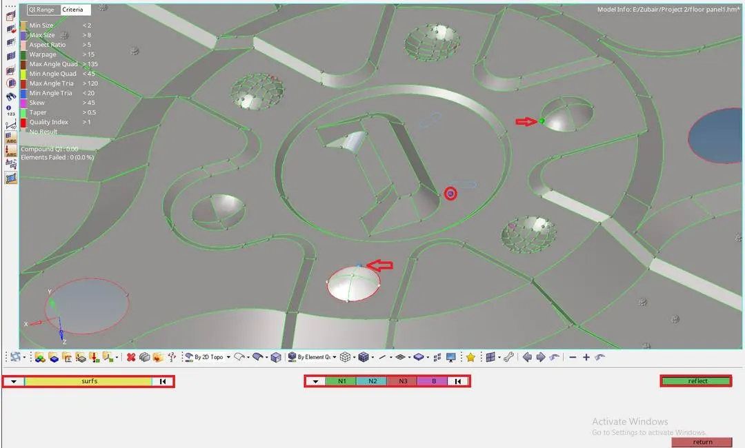
Figure 9.
Step 8: Once the Midsurface is created with proper shared edges check again for geometry .
- Toggle the lines that may fail for minimum length.
- Remove the unwanted points on the surface that can lead to element fail.
Midsurface check by colour contrast
- Turn on the parent & midsurface, change and give them contrasting colour.
- This will help indicate the for any missing midsurface or improper midsurface.
- Here in this one can easily identify the orange midline and the orange points of midsurface on the blue parent surface. (refer figure 10)
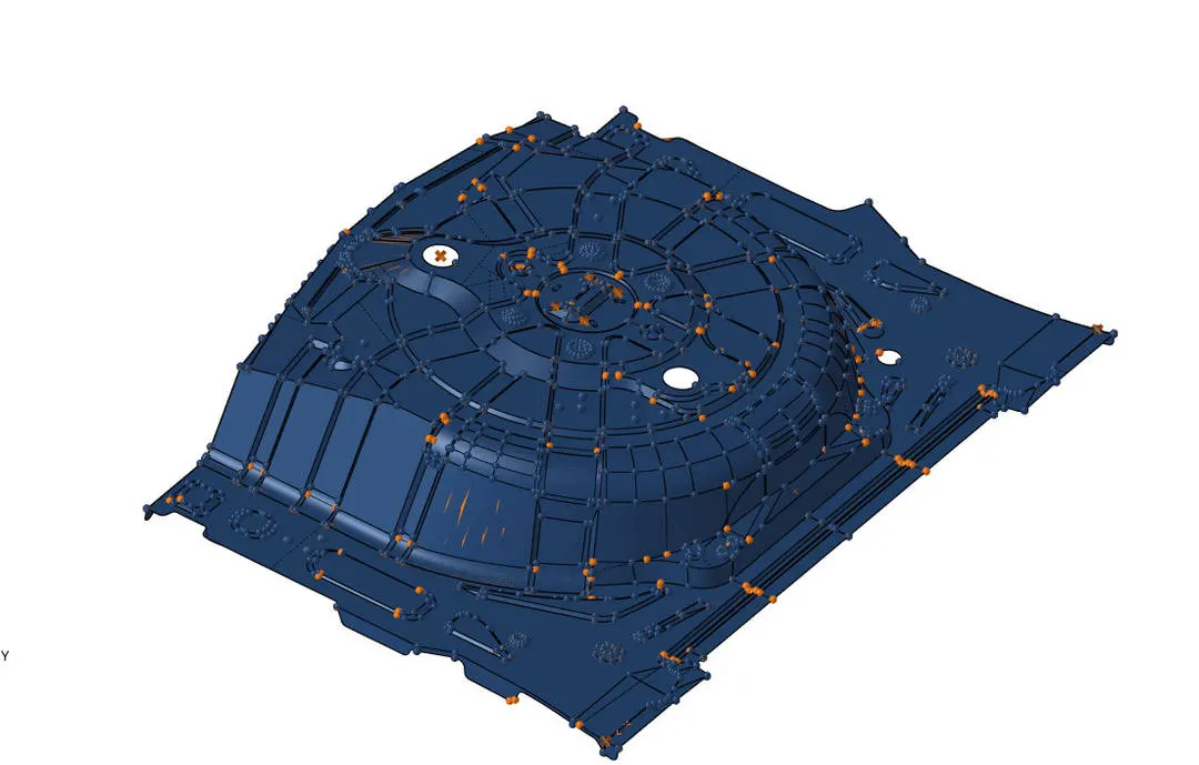
Figure 10.
Step 9: Moving to third major step i.e. Meshing.
- So first assig the quality criteria vaslues for the desired mesh.
- Go to prefrences > quality criteria from top tab.
- Given quality criteria are
Target Element Length = 5mm
| S.N | Quality Criteria | Value |
| 1 | Aspect Ratio | 5 |
| 2 | Skewness | 45 |
| 3 | Warping | 15 |
| 4 | Taper | 0.5 |
| 5 | Min. Length | 2mm |
| 6 | Max. Length | 8mm |
| 7 | Min angle Quad | 45 |
| 8 | Max angle Quad | 135 |
| 9 | Min angle Tria | 20 |
| 10 | Max angle Tria | 120 |
| 10 | Tria % | 10 |
TIP : To check for any unwanted points and lines left that can cause element fail for minimum length. we can give a mesh to whole component in one shot and turn on the quality for minimum length only rest can be resolved.
Once mesh is created go to quality index and select save failed.
- Go to Mask option (shortcut: f5) from options select elements.
- From extended entity selection menu select Retrieve.
- Select mask and select reverse all. (refer figure 11)
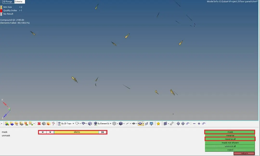
Figure 11.
Or you can manually check for elements failing.
Go to Geoms>Temp nodes select the elements and select add or cilck middle mouse button for confirmation. (refer figure 12)
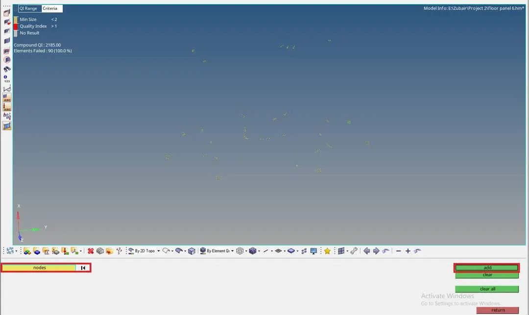
Figure 12.
After giving tempnodes for failing elements delete the elements and fix the geometry where temp nodes are given.
Step 10: Start meshing from a complex area or the area which is converging (refer figure 13)
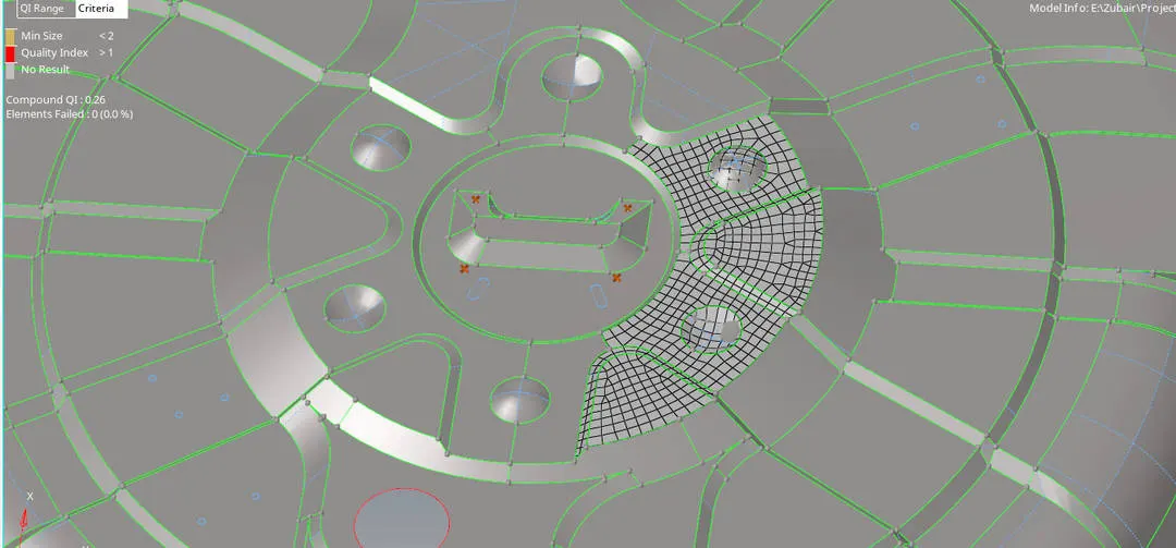
Figure 13.
Mesh part by part by part. go to mesh panel from 2D> Automesh
- Select Size and bias option
- Keep target element size as 5
- Do mesh with Elems to surf comp : will keep mesh on component irrespective of current component.
- first order: keeps the mesh in first order
- Keep connectivity: keeps the mesh connected to adjacent meshed surface.
- flow: align size: keeps th mesh in proper alignment and elememnt size within range
- map: size skew: keeps the elements size average throughtand avoids skew elements.
- link opposite edges with aspect ratio Auto: keeos equal number of nodes at opposite ends of surface to give a good mesh. (refer figure 14)

Figure 14.
Meshing at sharp corners
Meshing at sharp corners gives either Element fail for skewness or
- If we toggle the line it won't capture feature properly and give element failing for warpage.
In this model there are many such corners like this shown below. (refer figure 15)
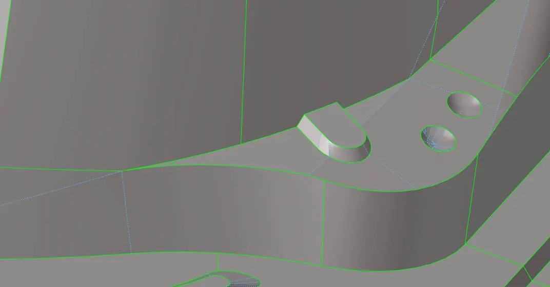
Figure 15.
Here we trim the corner surface with distance 2 mm as our minimum elemnt size criteria is 2mm.
- Now mesh the corner with adjacent areas and go to 2D> replace and Select Replace and select one node and from select another node.
Keep the mid node check box on so as to get tria between two surface to capture the surface and compromise little. (refer figure 16 a & 16b)
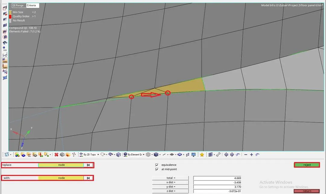
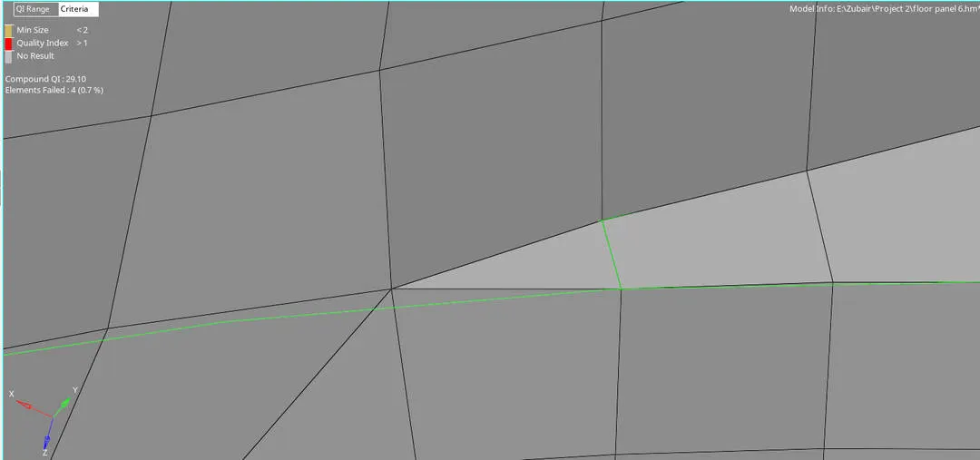
Figure 16 (a) Figure 16 (b).
Meshing at Holes
Step 12: To get a good mesh at holes we need to make the nodes at holw even and then rotate. make the nodes even while meshing.
- Create a node at center of circle by Geom>Nodes>Arc center.
- From option Select lines and select circle and select create.
Step 13: Now rotate and make the side of hole parallet to nearest edge. to rotate go to Tool>Rotate and selects nodest to rotate.
- Select N1, N2, N3 and base point as centre point.
- Put value 5 degree in angle and click rotate+/ rotate-. (refer figure 17)

Figure 17.
Step 14: Now go to auto mesh (Shortcut: f12).
- Select elements , from extended entity selection option select by Geom and select elements with rotated circle nodes.
- Select anchor nodes and select the nodes on circle. Basically anchor nodes freezes the selected nodes and rest nodes are remeshed.
Hence making it a good mesh flow around hole without trias touching to it. (refer figure 18)
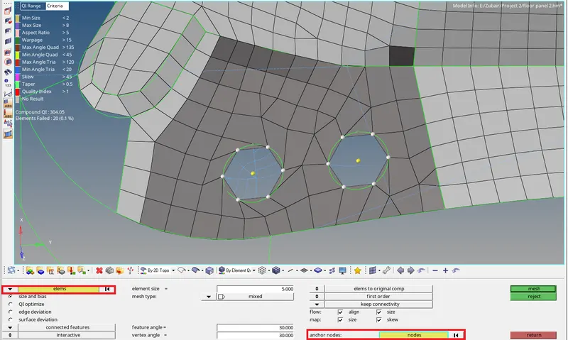
Figure 18.
Tip: Resolve the quality issues while meshing the surface itself and do not leave failed elements to resolve after finishing mesh.
Rules to have a good mesh:
- Maximum feature capturing is recommended.
- Reduce number of trias as much as possible
- Avoid surface with more tria concentration
- No trias touching the edges
- No opposite trias
- No trias in Fillet and hemmings
- No rotational Quads
- No back to back touching trias
- No tria touching another tria.
CHECKS:
=Trias in mesh
Once after the mesh is done Check for mesh violating trai rules. To get better view of tria in the visulization tab select by Config
It will show the trias and quads in contrasting colours which make easy to look out for trias.
Resolve the opposite trias, drag trias touching the edge wherever possible, drag apart tow or more touching trias. ( always give smooth after draging tria shift + f12) (refer figure 19)
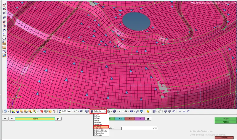
Figure 19.
.
=Free edge check by to junction and free edge
To check free edge go to Tools>edges (shortcut : shift + f3) and select elements and select free.
Select find edges. ( Rename the component created for free edges ^edges to free ) Aslo taking t-connections (yellow lines) to get a proper view.
- Again select elements and change free to T-connections select find edges
- Then hide the surface and mesh. look for any single red line in between meshed elements. (refer figure 20)
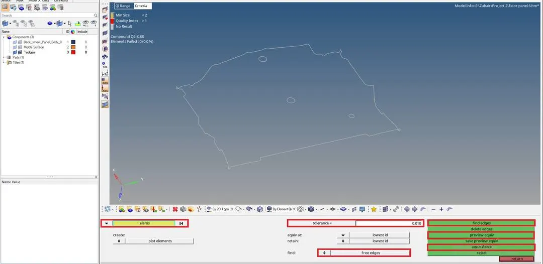
Figure 20.
Now if there are any such free edges, from same Edge panel select elements give tolerance as 1 and select preview equivalence.
- The free edge nodes within tolerance range will appear as green dots. Select equivalance and the nodes will be pasted.
- Even after equivalencing the nodes does not get pasted then do manual pasting or replacing nodes.
- Go to Geom> node edit (shortcut f3) select replace node and with as another node. Hypermesh will replace one node with other and hence no free edge will be left.
Step 15: At last check for element normals. Go to Tool> normals. Setlect elements and select display. If all the elements on one side do not have same orientation (colour) then adjust them. Select Adjust. it automatically adjusts the normals. If it dosent there is a chance of duplicate elements. (refer figure 21)
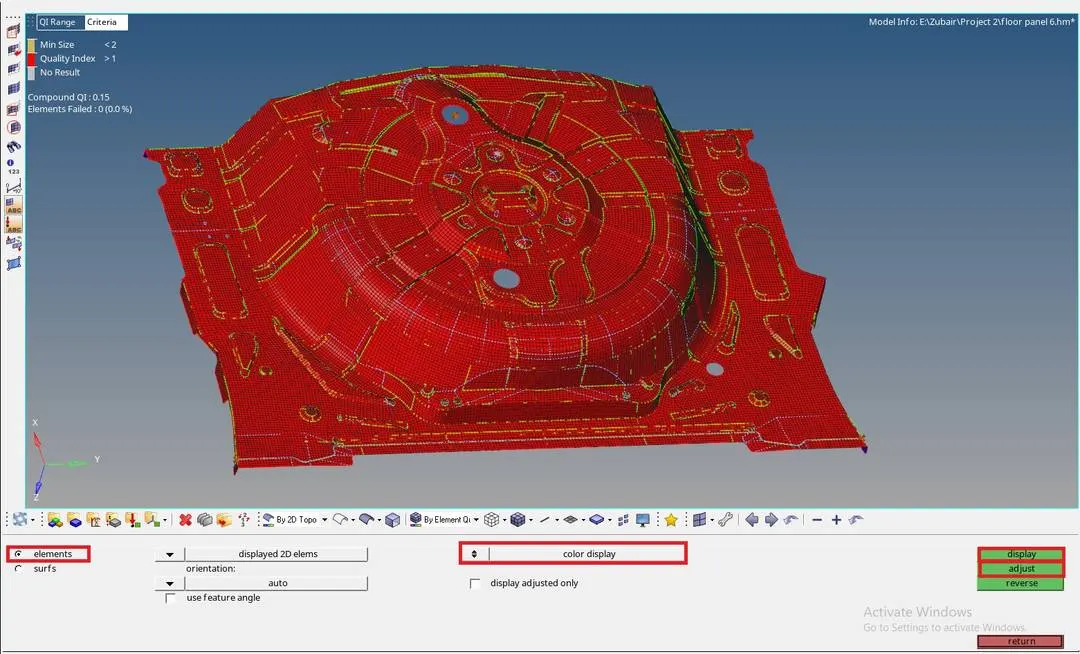
Figure 21.
Conclusion: The spare-wheel well floor panel is meshed with optimum meshflow and 2.1% tria. with assigned thickness and zero elements failing for quality.
Final image: