Week 6 Challenge
DESIGN AND ANALYSIS OF BRIDGE WITH PIPE LOADS
AIM
To Design and analyse a Truss bridge with Pipe loads using STAAD Pro. Software.
INTRODUCTION
As per the given data with reference of CPHEEO and standard formulas the DI Pipe load is being calculated manually.
Live load of DI pipe = π/4 x (d)^2 x Unit weight
Self weight of DI pipe to be referred from CPHEEO class K9 DI pipe data table
Total load = Self weight + Live load
FOR 200mm DIA DI PIPE
Live load of 200mm DI pipe = π/4 x (0.2)^2 x 10
So,Live load of 200mm DI pipe = 0.314 KN/m
Self weight of 200mm DI pipe = 0.194 KN/m (Referred from CPHEEO class K9 DI pipe data table)
Total load of 200mm DI Pipe = 0.314 + 0.194 = 0.50 KN/m
FOR 700mm DIA DI PIPE
Live load of 700mm DI pipe = π/4 x (0.7)^2 x 10
So,Live load of 700mm DI pipe = 3.84 KN/m
Self weight of DI pipe = 1.12 KN/m (Referred from CPHEEO class K9 DI pipe data table)
Total load of 700mm DI Pipe = 3.84 + 1.12 = 4.96 KN/m
PROCEDURE
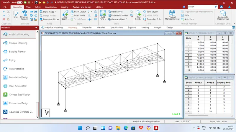
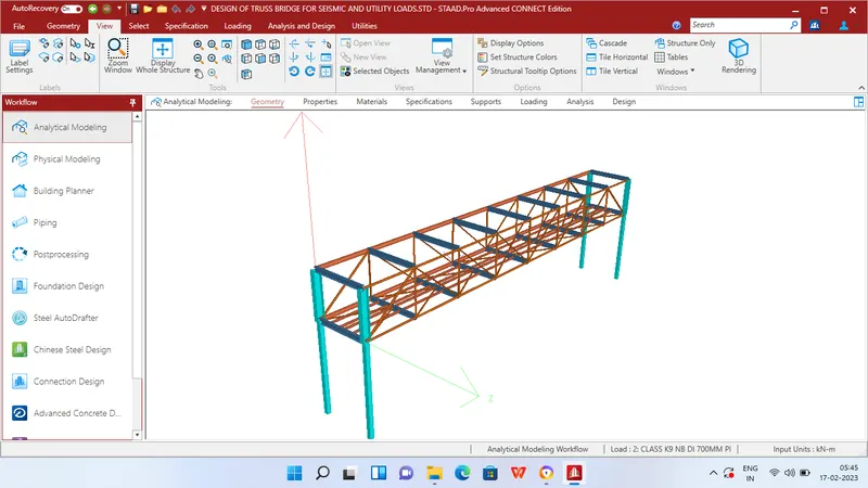
Step 1 - Create Nodes by entering the corresponding X/Y/Z values in the Node table for Creation of geometry for Truss bridge structure with elements such as Piers,Beams,Deck slab etc.,
Step 2 - After creating the nodes connect those nodes with add beam option.
Step 3 - Then Click specification tab and click fixed support tab
Step 4 - After that in create support dialog box add fixed support for all the piers in the geometry using assign for selected nodes option.
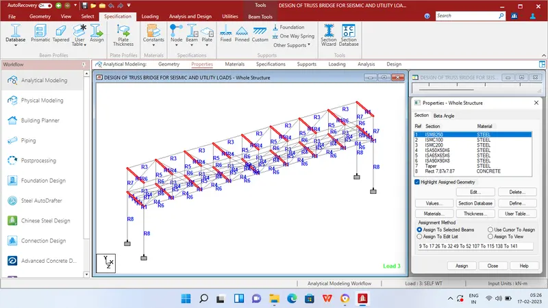
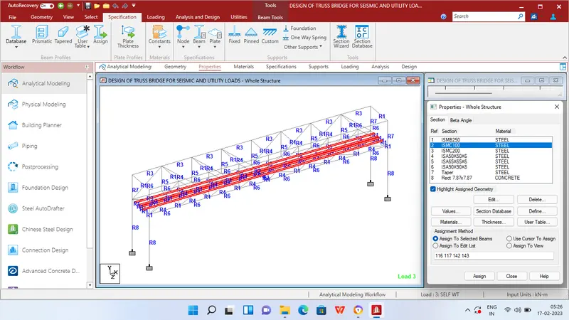
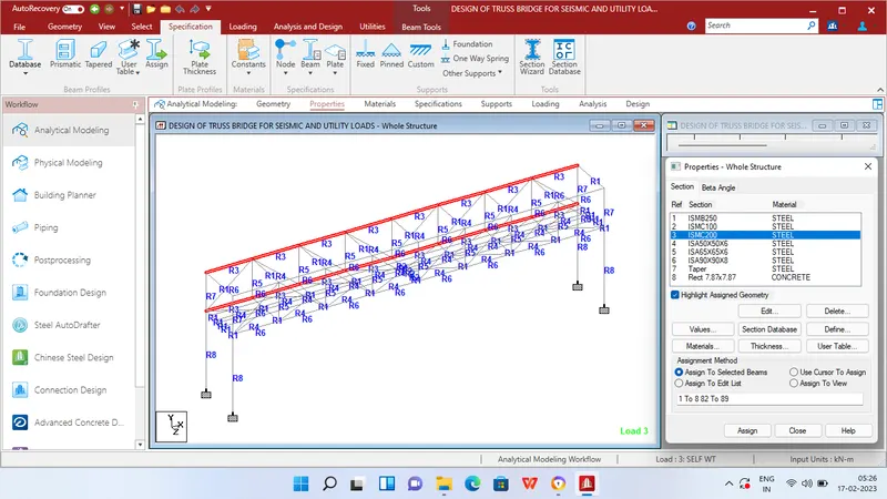
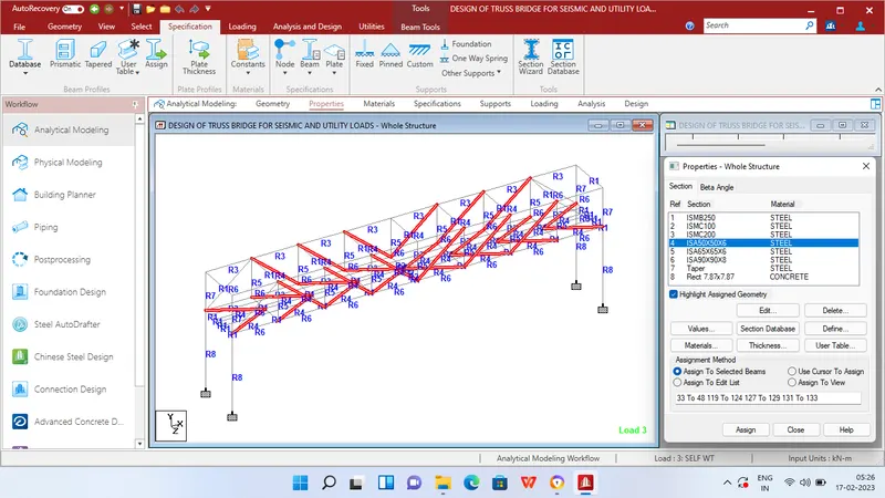
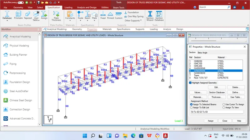
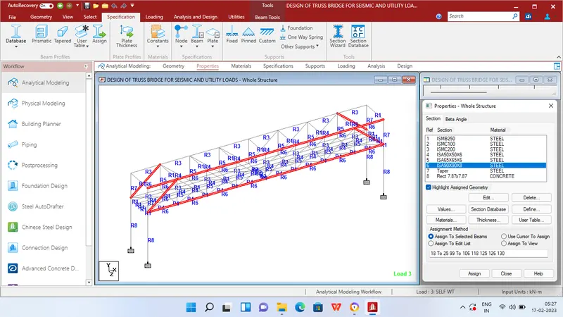
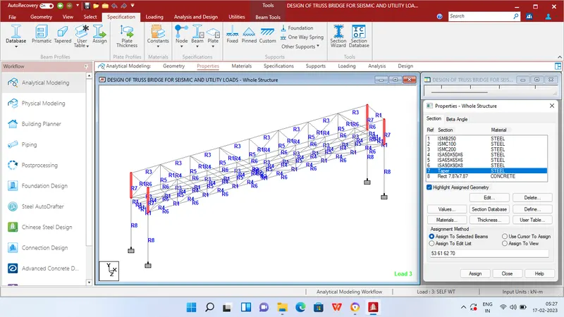
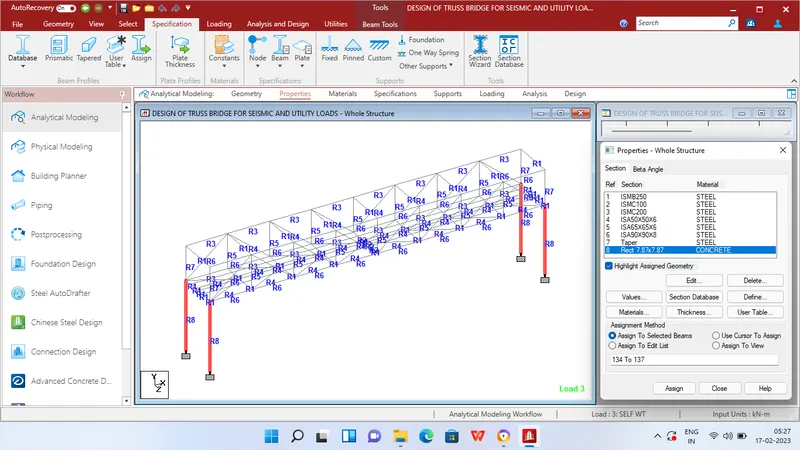
Step 5 - Then in Properties tab click Prismatic and add the I-Sections,Angle members,C Channels to the respective beams as given in the question data
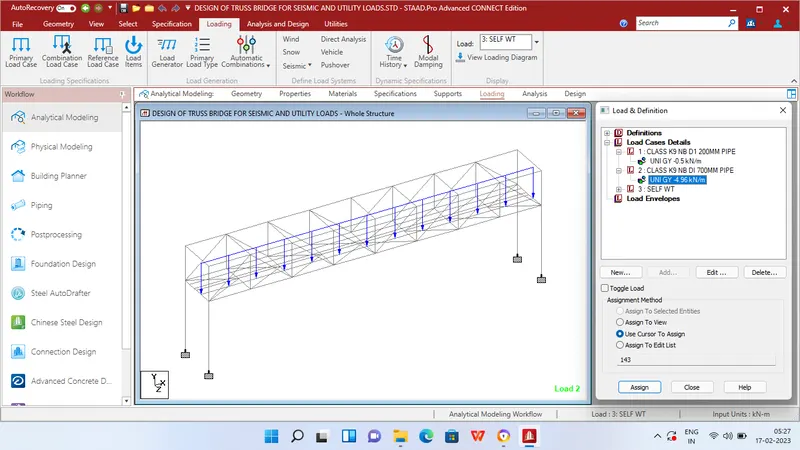
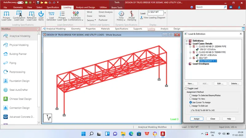
Step 6 - After adding the properties click Loading tab and add load cases for Self weight,200mm dia and 700mm dia pipe .
Step 7 - Then apply Member load as 0.5 KN/m and 4.96 KN/m for LOAD CASE 1: CLASS K9 200mm DI PIPE and LOAD CASE 2 : CLASS K9 700mm DI PIPE respectively to the beams created for pipe loads.Then apply self weight to the entire geometry.
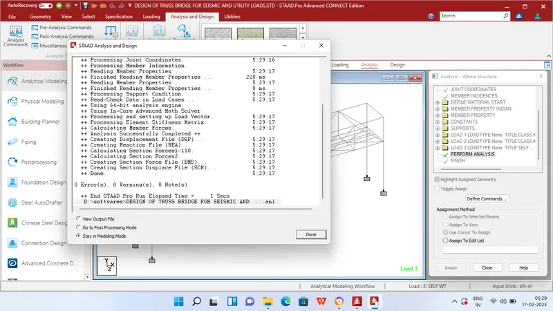
Step 8 - After applying the loads in analysis and design tab define commands for PERFORM ANALYSIS and click run analysis.
RESULTS

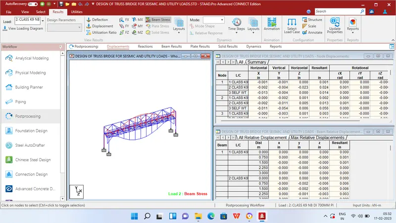
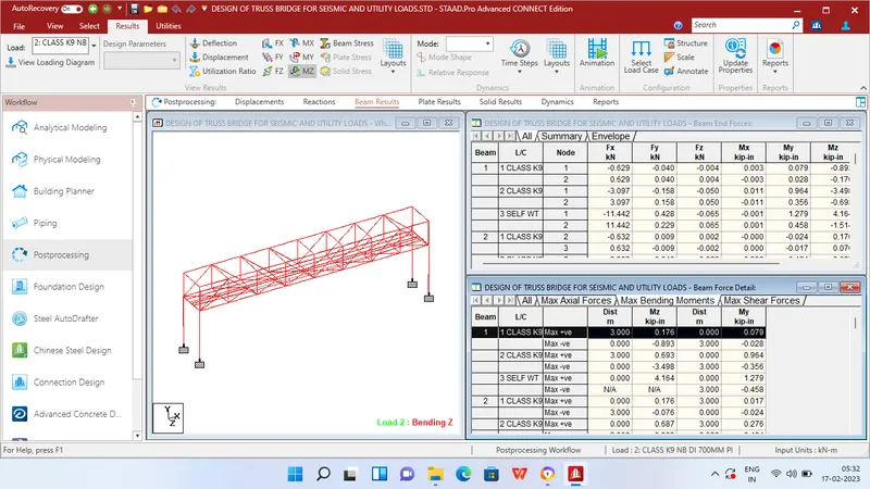
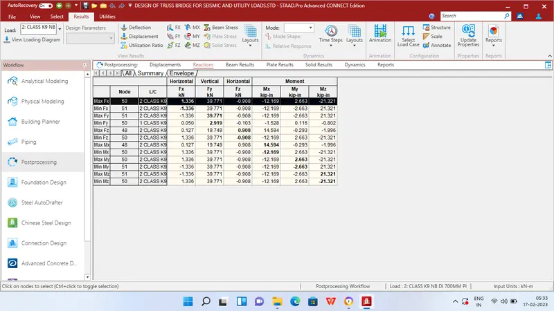
MAXIMUM BENDING MOMENT AT SUPPORT
Mx = 14.594 KN/m at Node 48
My = 2.663 KN/m at Node 50
Mz = 21.321 KN/m at Node 51
MAXIMUM SHEAR FORCE AT SUPPORT
Fx = 1.336 KN/m at Node 50
Fy = 39.771 KN/m at Node 51
Fz = 0.908 KN/m at Node 48
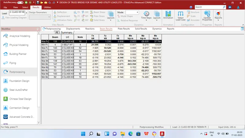
MAXIMUM BENDING MOMENT AT BEAMS
Mx = 643.35 KN/m at Beam 139
My = 74.486 KN/m at Beam 70
Mz = 1192.667 KN/m at Beam 143
MAXIMUM SHEAR FORCE AT SUPPORT
Fx = 39.771 KN/m at Beam 136
Fy = 59.52 KN/m at Beam 143
Fz = 3.759 KN/m at Beam 53
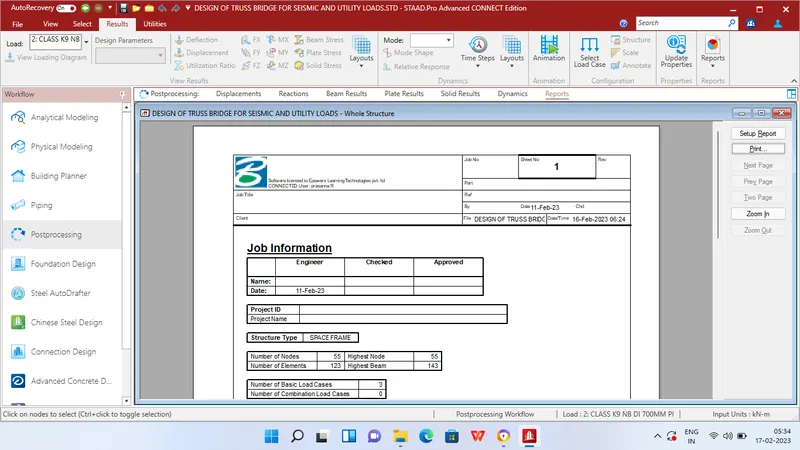
REPORT