Week 6 Challenge
Aim of The Challenge : To Model & Analyse the Bridge Section which is having 24.0m length span and 3m Width, for 2 Different Pipe Loads, 700 Dia NB D and 200 Dia NB D Pipe, and Location of the Bridge is Stated near Narmada River, in Staad Pro and Brielfy Identify The Displacement, Bending Moments, Shear Forces & Plate Stresses Developed on the Structure while subjecting to Pipe Load Conditions.
Introduction : As we Know Staad Pro is Desinged and Maintained by Bentley Systems Software Company, Staad Pro is used for Structural Analysis and Design Purposes, As the Given Structure is a Bridge of 24m span and 3m width, we have to analyse the structure for Pipe Loading and briefly describe the analysis results.
Procedure :
Calculations :
SELF WEIGHT OF DI PIPE
- For 700 mm dia and class K9 weight = 217.19 Kg/m = 2.1719 KN/m
- For 200 mm dia and class K9 weight = 45.28 Kg/m = 0.4528 KN/m
LIVE LOAD
- For 700 mm dia = 3.14 x (0.7 x 0.7) x 10 = 15.386 KN/m
- For 200 mm dia = 3.14 x (0.2 x 0.2) x 10 = 1.256 KN/m
TOTAL UDL
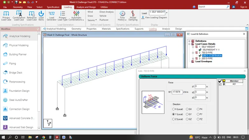
- For 700 mm dia = 15.386 + 2.1719 = 17.5579 KN/m
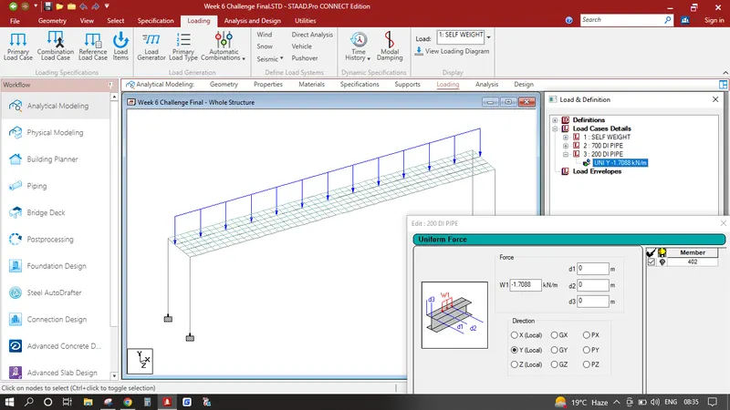
- For 200 mm dia = 1.256 + 0.4528 = 1.7088 KN/m
Modeling :
- 1. Open Staad Pro and Create a new Project and select Metric in Unit, this will allow us to model the structure in metres as shown in the given diagram and get results in Kn.
- 2. Input the origin node as 0,0,0 for and select the node and perform translational repeat number of steps 3 and distance is 1 Click Link Steps in Z direction, select all the beams and perform translational repeat number of steps 1 and distance is 24 Click Link Steps in X direction, select all the corner nodes press CTRL C+ CTRL V input -6 in Y and press ok which creates our Piers.
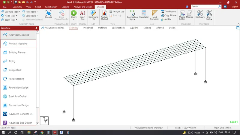
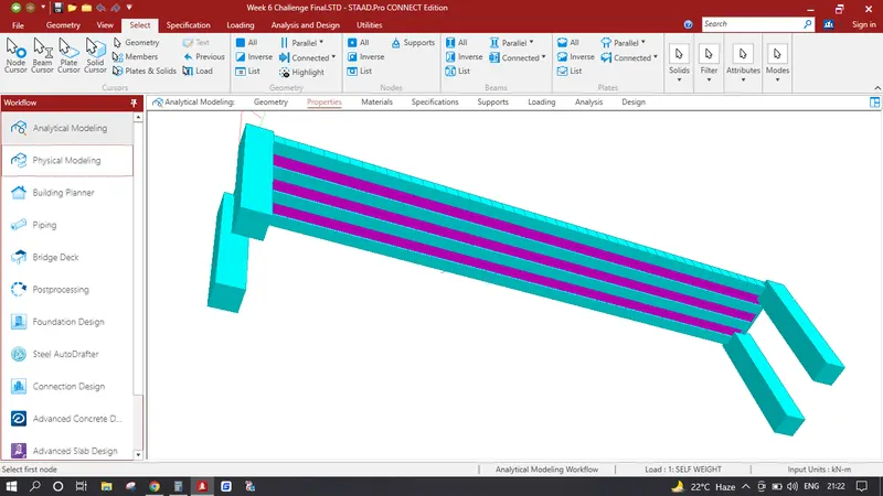
- 3. Create a Deck Slab Select the corner node press CTRL C+ CTRL V input 0.5 in X and press ok, Select both the nodes press CTRL C+ CTRL V input 0.5 in Z and press ok. Create a Plate Inside these nodes select the plate and perform translational repeat number of steps 47 and distance is 0.5 in X direction, again select all the plates and perform translational repeat number of steps 5 and distance is 0.5 in Z direction which creates our Deck Slab.Which is Shown in the Image Below.
- 4. Now we can have to Provide Supports in Pier Bottom Select all the bottom Nodes Click on Specification in Upper Tab Create a Fixed Support and Assign the Bottom Nodes to Fixed end Support.
Assingning Specifications :
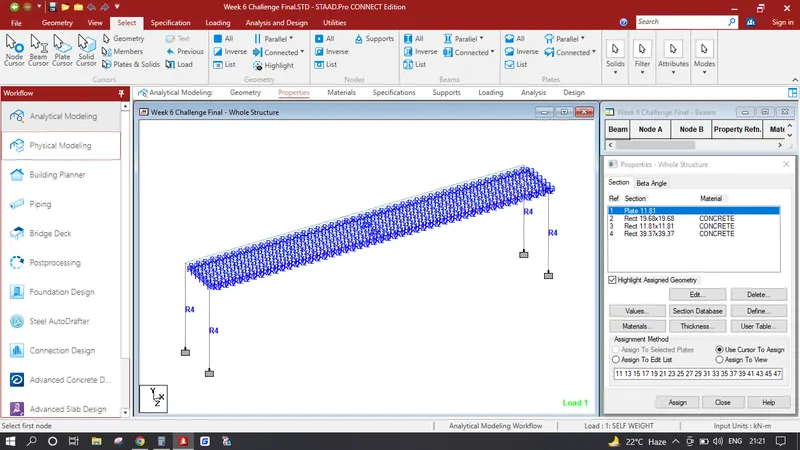
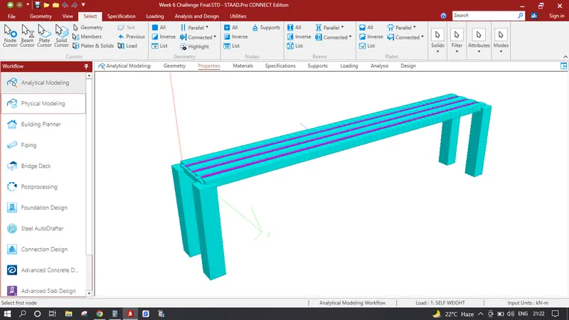
- 1. Click on Specification Tab click on Define click on Rectange Add a Pier Size of 1.0 x 1.0 m Click Add, Again Click on Define Click on Rectange Assign the Vertical Girders as 0.5 x 0.5 m. Again Click on Define Click on Rectange Assign the Cross Girders as 0.3 x 0.3 m, Again Click on Plate Thickness input 0.3m click add.
- 2. Select all the Piers and Assign the Specification having 1.0 x 1.0 m Configuration, Similarly Click on Select click on Parallel under Beams click on parallel to X Which selects all the Vertical Girders and Assign the Specification having 0.5 x 0.5 m Configuration, Similarly Click on Select click on Parallel under Beams click on parallel to Z Which selects all the Cross Girders and Assign the Specification having 0.3 x 0.3 m Configuration, Similarly Select all the Plates and Assign the Specification having plate thickness 0.3m Configuration, After assigning all the properties the model should look like the image provided below.
Adding Pipe Loadings:
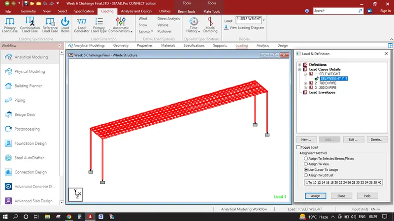
- 1. Click on Load Cases Details Click add Write Name Self Weight Click add, again click on Self Weight click add under self weight give the value as -1 in Y direction, after adding select the created self weight and assing to view which assigns the self weight of the whole structure to our model.
- Click on Load Cases Details Click add Write Name 700 DI PIPE click add, again Click on 700 DI PIPE click add and click on Uniform Force under Member Load and input values as shown in the diagram. apply this load in (X-0, Y-0, Z-2) node.
- Click on Load Cases Details Click add Write Name 200 DI PIPE click add, again Click on 200 DI PIPE click add and click on Uniform Force under Member Load and input values as shown in the diagram. apply this load in (X-0, Y-0, Z-1) node.
Analysis & Results :
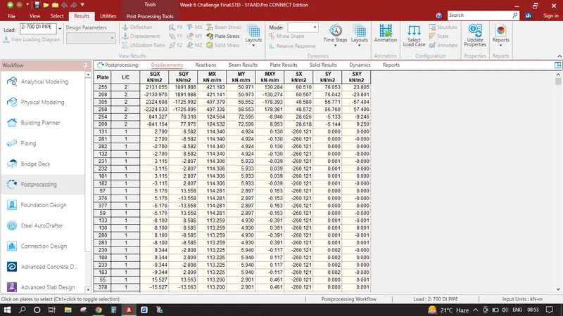
- 1. Click on analysis and design run analysis, again go to post processing
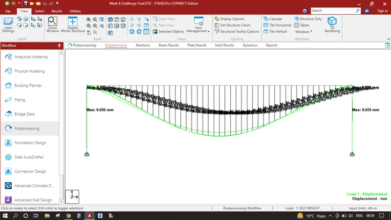
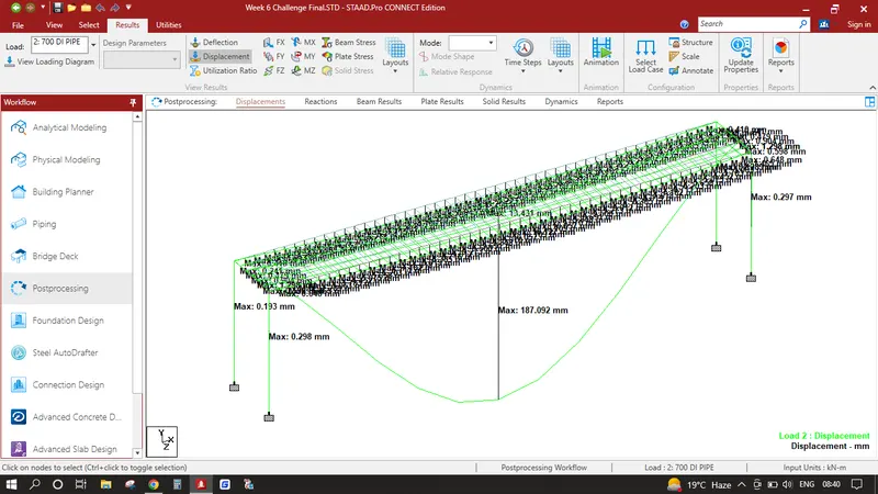
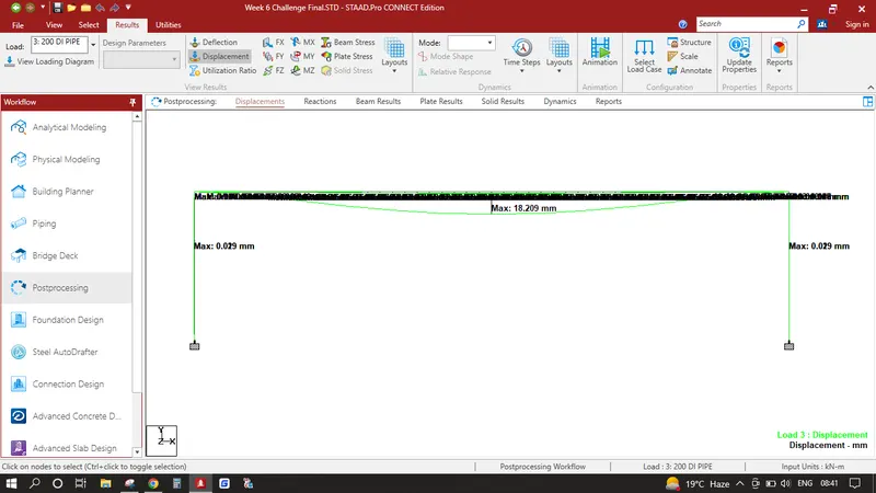
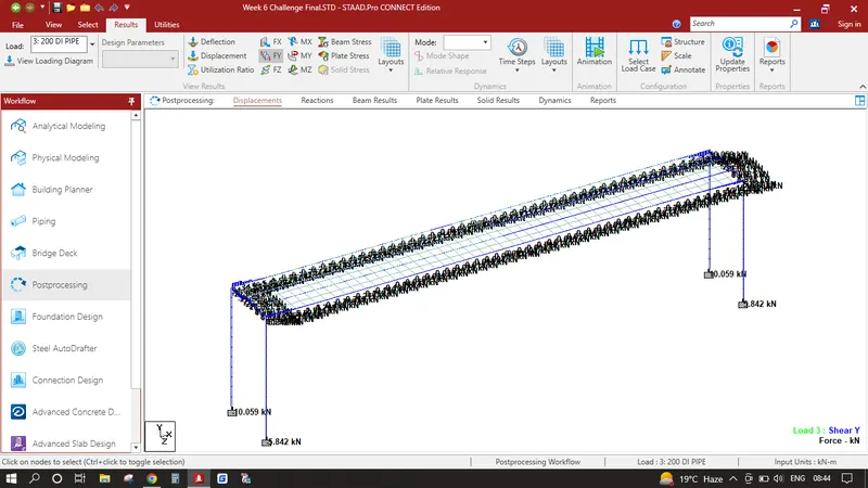
In Results Tab Displacement Pattern show in the image below
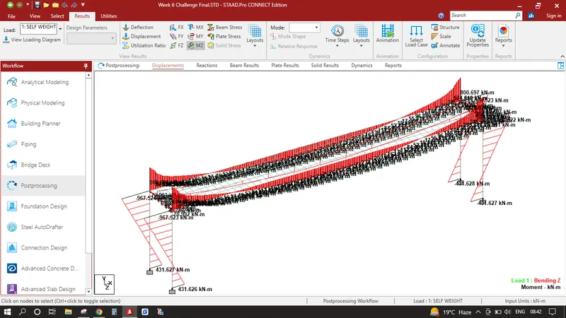
In Results Bending Moments shown in the image below
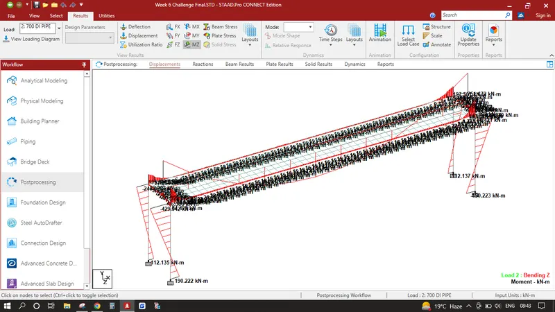
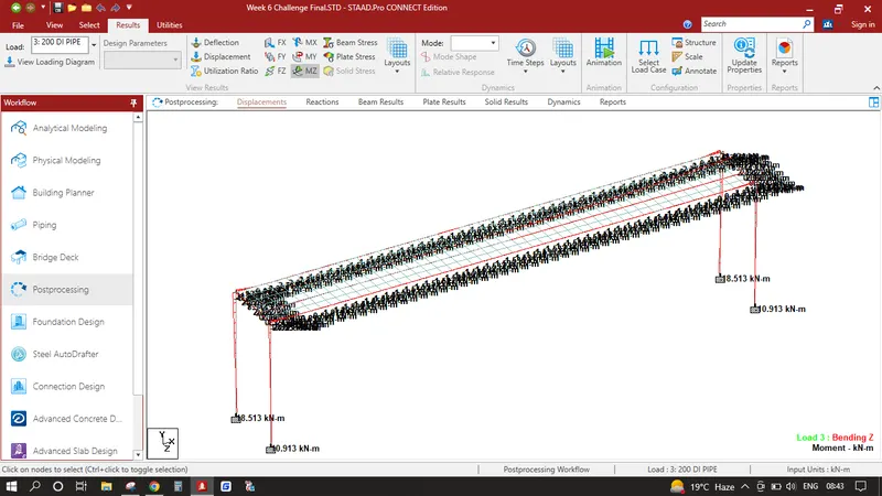
In Results Shear Stresses are shown in the image below
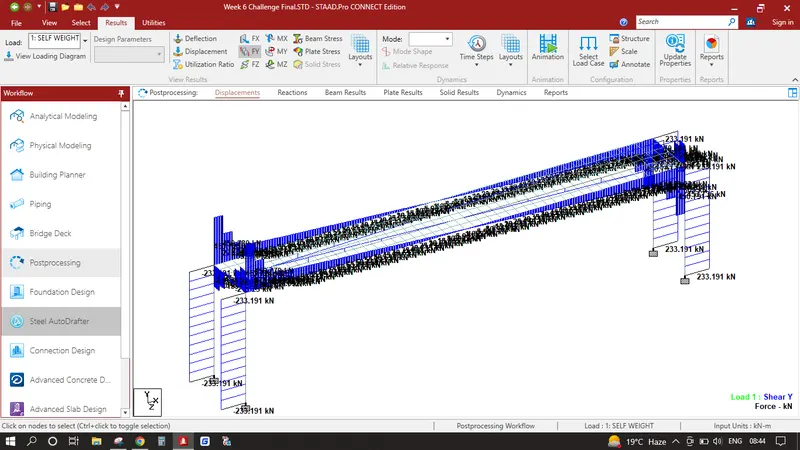
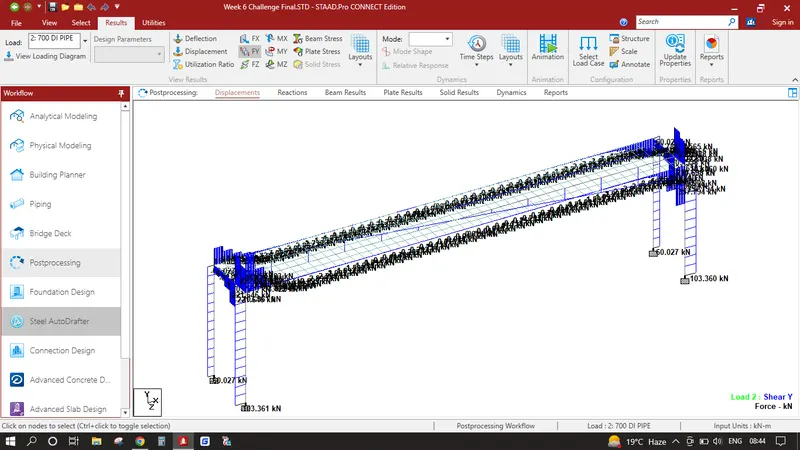
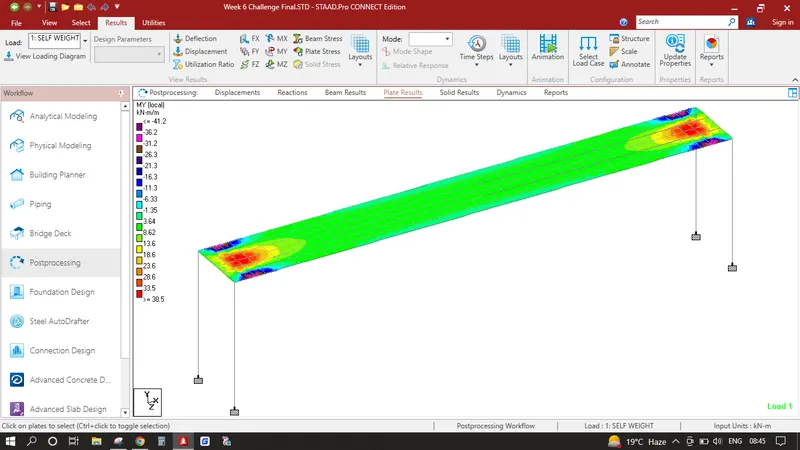
In Results Plate Stresses in MY Local are shown in the image below
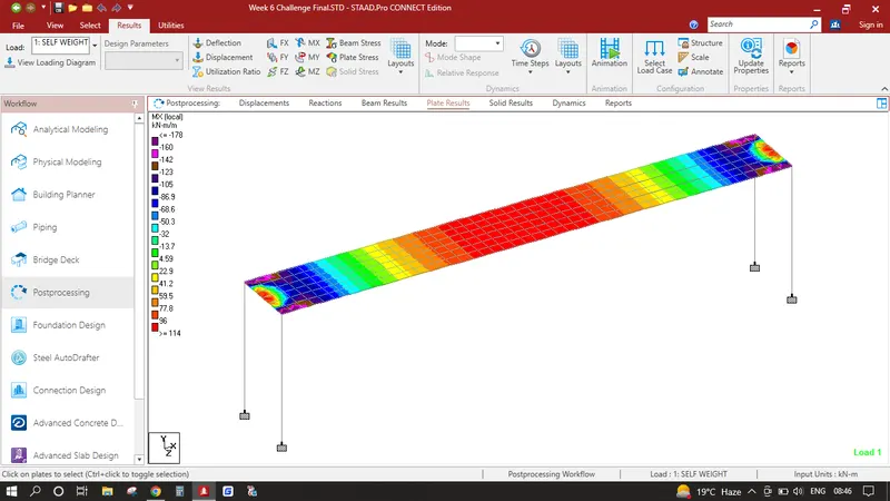
In Results Plate Stresses in MX Local are shown in the image below
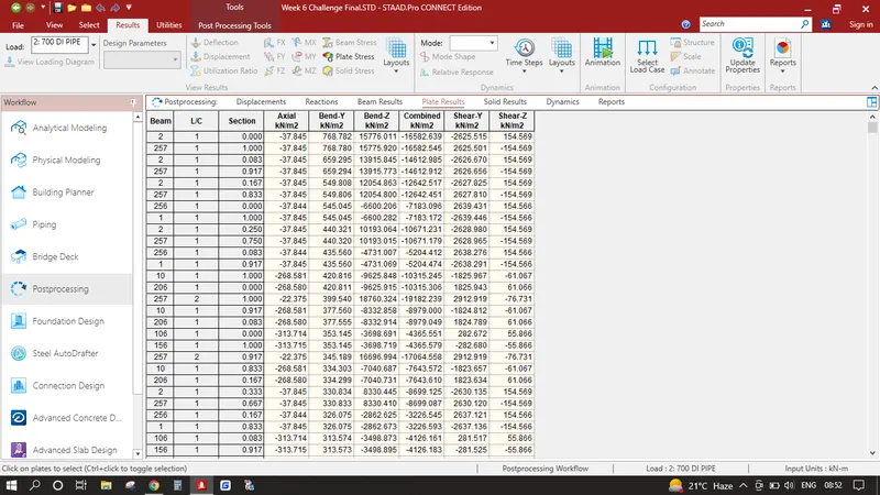
Select all the beams click on reports click on Beam Stresses click on Bending MY click ok
Select all the Plates click on reports click on Plate Stresses click on Bending MX click ok