Week 6 Challenge
Aim : To calculate the pipe loads for the bridge located in the banks of the river Narmada .
Given data :
Width of the bridge – 3 m
It is located in banks of the river Narmada .
Pipe dia ( N B , Ductile iron pipe ) – 700 mm
Pipe dia ( N B , Ductile iron pipe ) – 200 mm
Span of the bridge is – 24 m
Theory : The Pipe load are calculated using the given formula below. The self weight of the pipe is given by CPHEEO manual. By referring the manual pipe loads are calculated.
The Calculation of pipe load is given by:-
Self weight for 700 mm NB dia of D.I pipe – 217.19 kg/m, 2.17kn/m
Live load due to flow of water = area x unit weight
= 0.38 x 10= 3.8 kn/m
Self weight for 200 mm NB dia of D.I pipe – 45.28 kg/m, 0.45kn/m
Live load due to flow of water = area x unit weight
= 0.031 x 10= 0.31 kn/m
Total load on bridge of 700 mm dia pipe = self weight + live load due to water flow
= 2.17 + 3.8 = 5.97 kn/m
Total load on bridge of 700 mm dia pipe = self weight + live load due to water flow
= 0.45 + 0.31 = 0.76 kn/m
Aim : To prepare the model in a STAAD Pro and perform the analysis and justify with the results.
Theory : The general steps to be create a STAAD Pro model is given below,
Step 1 : Create the nodes by using the nodes cursor.
Step 2 : Joining the nodes by using the respective beam plate cursor.
Step 3 : Supports given to the nodes whether its pinned or fixed or any other custom supports
Step 4 : specifications given to the respective beams plates
Step 5 : Assign the live load as per calculation
Step 6 : Save the model and perform the analysis
Step 7 : The results are obtained and discuss with the results
Step 8: Take the print out of report of necessary results.
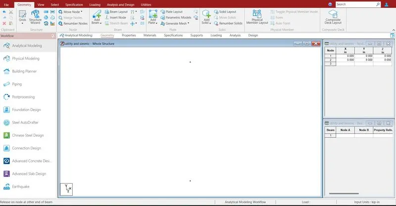
Creating the nodes by using node cursor.
Open the STAAD Pro window > Select > Node cursor > enter the value with respect to X Y Z axis > click enter.
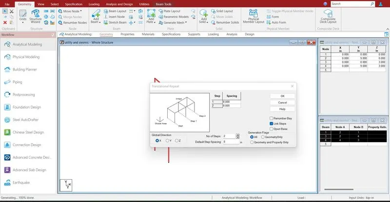
Join the nodes by using beam cursor.
Select > beam cursor > join by dragging the mouse or enter the node numbers > click enter
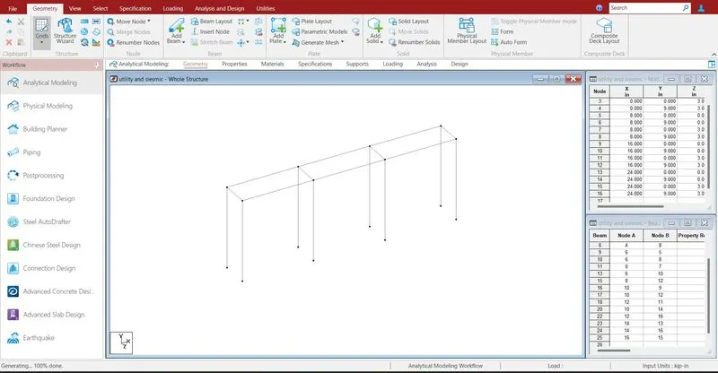
Model has been prepared.
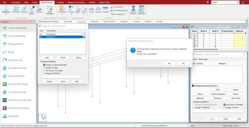
Supports are given to the respective nodes.
Specifications > Supports > select the supports > click enter
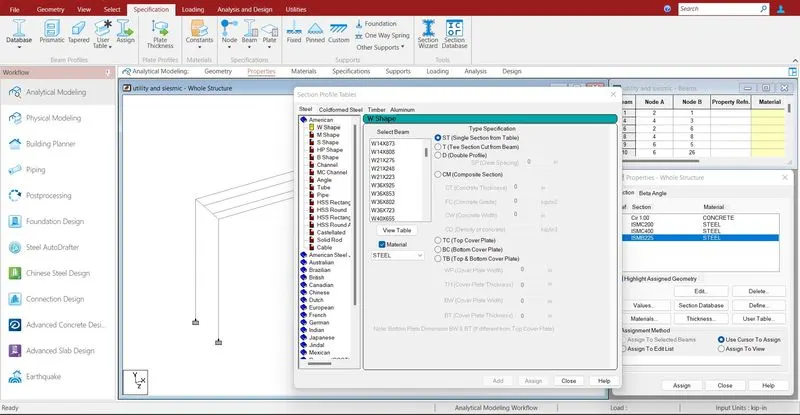
Defining the properties to the beam and pier.
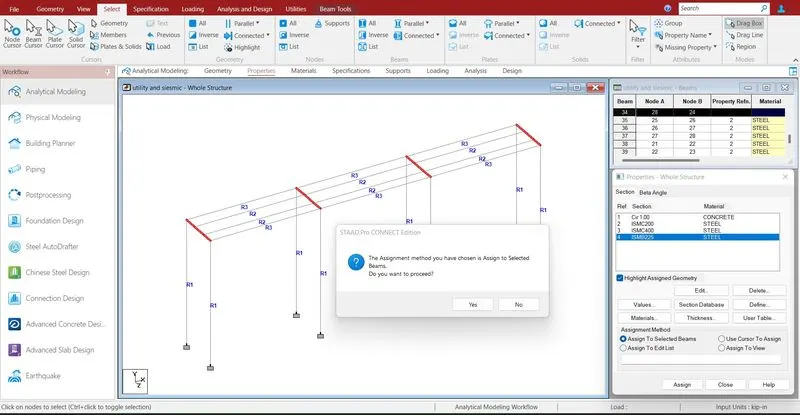
Assigning the properties to the beam .
Specification > Prismatic > Rectangle > enter dimensions > select the beam > assign the properties to selected beams.
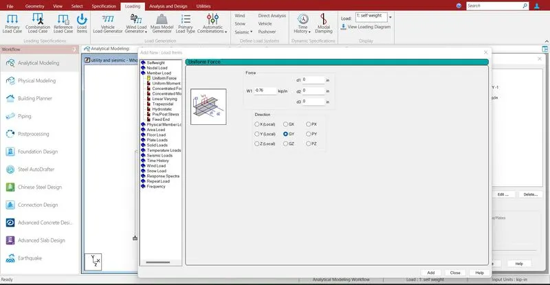
Defining the load cases .
Loadcase > utility load > Add
Load case > Add > member load > enter the load value > add
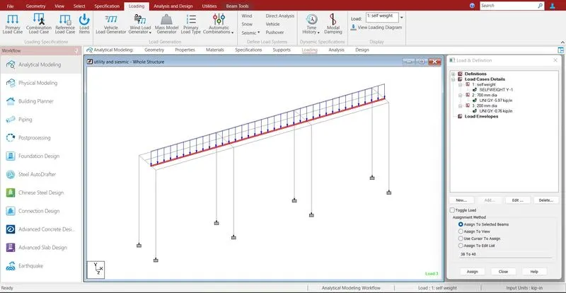
Loads are assigned.
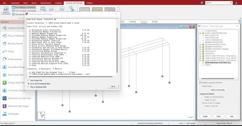
Run analysis > go to post processing mode > Results
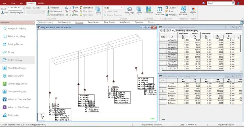
The reactions are generated at the end of the nodes .
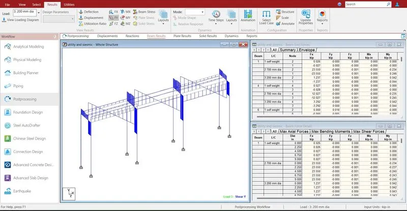
- The maximum shear force at x direction is 23.88 KN.
- The minimum shear force at x direction is 0.02 KN.
- The maximum shear force at y direction is 31.013 KN.
- The minimum shear force at y direction is -24.046 KN.
- The maximum shear force at z direction is 0.002 KN.
- The minimum shear force at z direction is -0.002 KN.
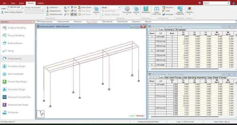
- The maximum bending moment at x direction is 1.191 KNm.
- The minimum bending moment at x direction is -1.191 KNm.
- The maximum bending moment y direction is 0.044 KNm.
- The minimum bending moment y direction is -0.250 KNm.
- The maximum bending moment z direction is 2.085 KNm.
- The minimum bending moment z direction is -58.552 KNm.
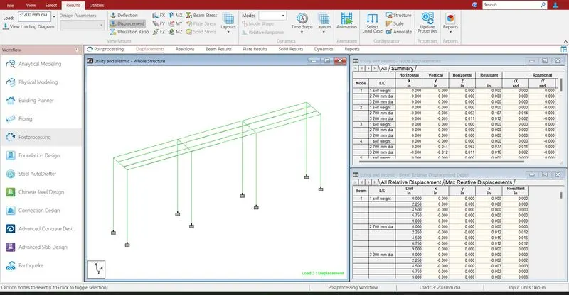
- The maximum deflection at x direction is 0 mm.
- The minimum deflection at x direction is 0 mm.
- The maximum deflection at y direction is 0 mm.
- The minimum deflection at y direction is -0.087 mm.
- The maximum deflection at z direction is 0.011mm.
- The minimum deflection at z direction is -0.063 mm.
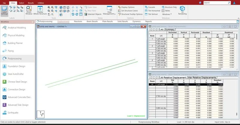
- Deflection of pipe load.
- Reports are taken printout which ever is necessary by using report option.
- In the report option we obtain the results of section forces, displacement, reactions, plate stresses.
- The exact report is to be taken further move to design process.