Week-6 Calculate the Stretch Ratio by comparing the ELFORM (-2,-1,1,2) with Ogden_Material Model.
AIM:
To create a solid cube with dimension 10 X 10 X 10mm in all direction. Ogden material is used which is a hyper elastic material. An uniaxial tensile loading is performed. One end of the box is constrained in x direction and the other is applied with displacement. While defining the section for this solid part, four different elform values are used to check how the elform values influences the result of the analysis.
To solve this non linear problem, implicit solver is used.
PROCEDURE:
- The given key file consist of ogden material card, then a solid block of 10 X 10 X 10mm is created using the command Mesh>shape mesher>box solid>enter x,y and z coordinates as 10>no of elements in x,y and z direction as 10>create>accept.
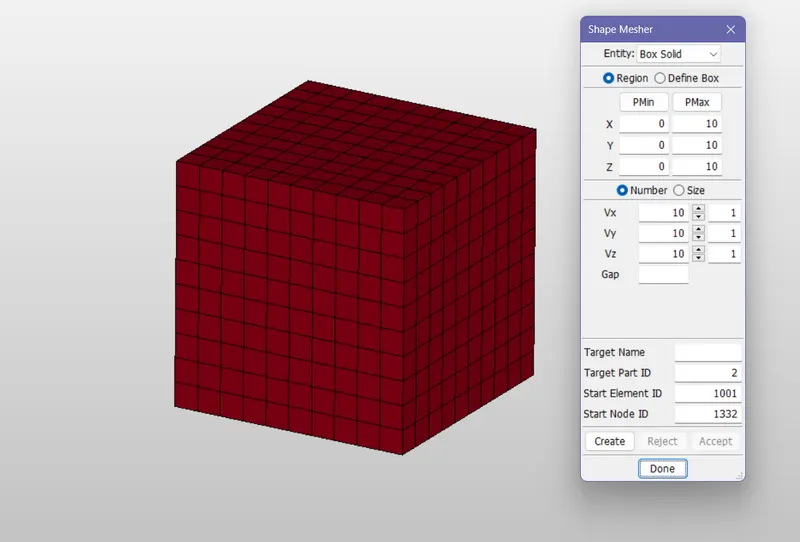
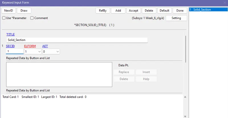
- After creating the box, we have to define the section for that go to keyword>Section>solid>enter section id and elform value and click accept.
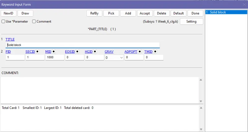
- Now go to part>select the section and material.
This analysis is splited into 4 cases:
CASE 1:
In section id, elform value is given as 1 ( constant stress solid element).
CASE 2 :
In section id, elform value is given as 2 ( Fully integrated S/R solid).
CASE 3:
In section id, elform value is given as -1 ( fully integrated S/R solid intended for elements with poor aspect ratio, efficient formulation).
CASE 4:
In section id, elform value is given as -2 ( fully integrated S/R solid intended for elements with poor aspect ratio, accurate formulation).
- Now go to part, select the section and material id for the created box and click accept.
- For creating boundary conditions, node set data need to be created for that go to model>create entity>Set data>set node> select one end of the nodes. Now go to Boundary SPC set>constrain in X direction> click ok.
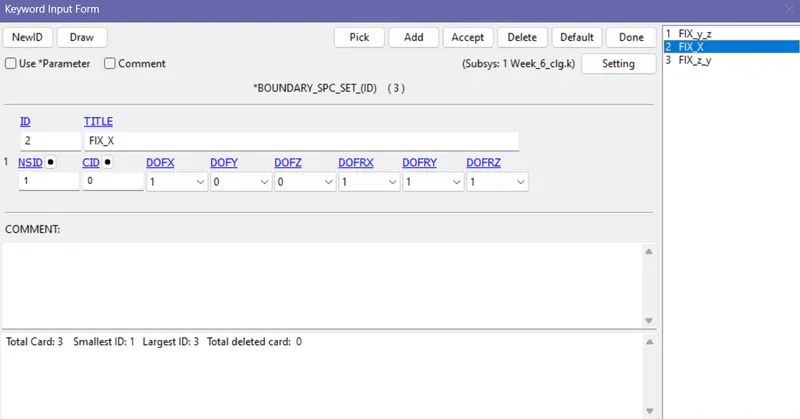
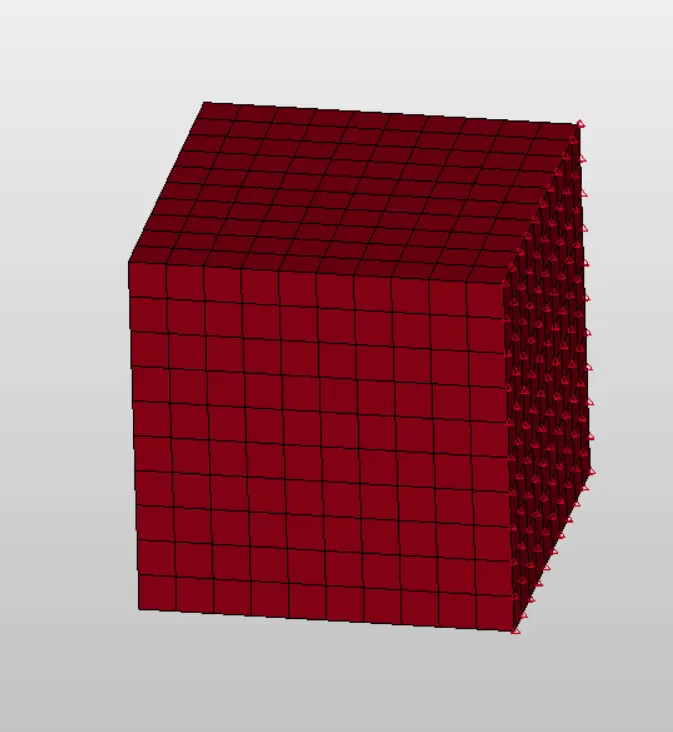
- Next constrain the set of nodes in the middle on y direction along z. Again constrain the set of nodes in the middle on z along y direction.
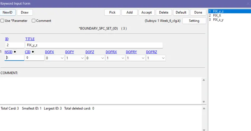
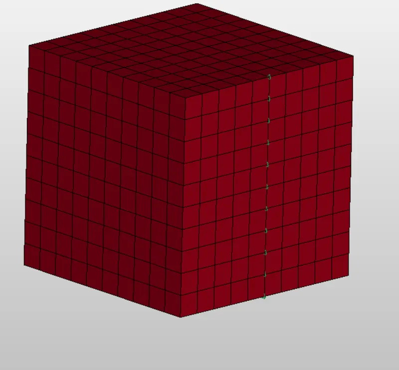
- Again constrain the set of nodes in the middle on z along y direction.
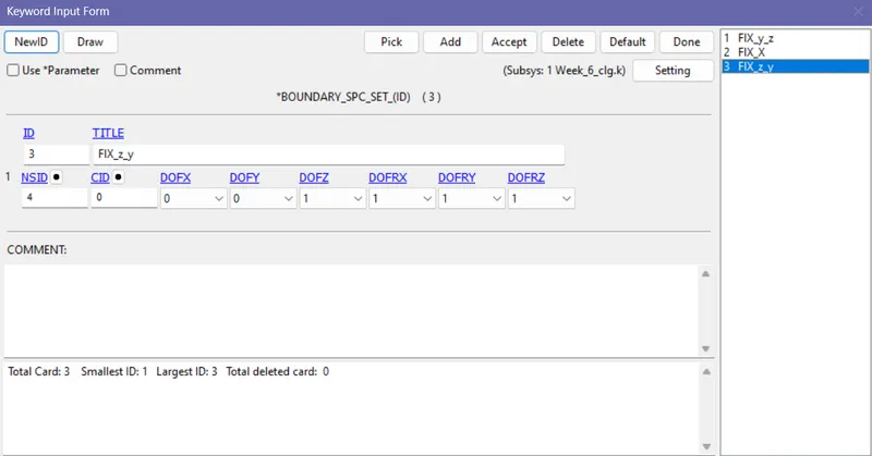
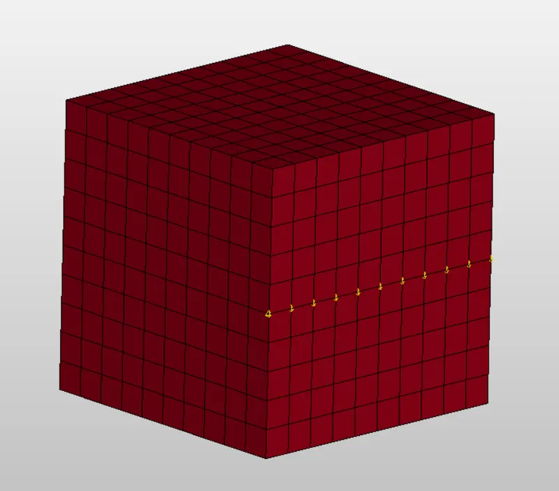
- The reason for giving this type of constrain is, while fixing the one end of the box in all the direction won't let decrease in diameter while stretching in x direction.
- After one end is constrained, the end is applied with load i.e., displacement. To attain a stretch ratio of 7, minimum load required need to be determined.
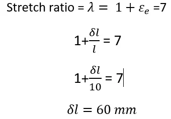
Where  is the minimum load required to attain the stretch ratio of seven.
CONTROL CARDS:
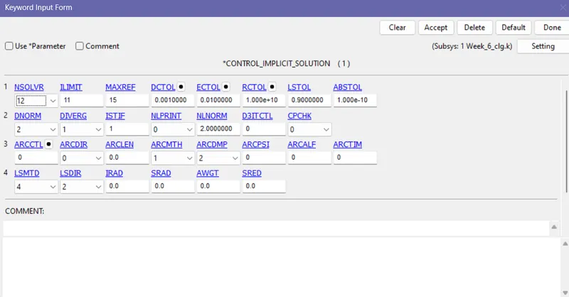
It is observed that the stress strain graph of hyper elastic material is highly non linear so implicit solver is used to solve the non linear problems.
- CONTROL_IMPLICIT_AUTO: It is used to control the time step size automatically during analysis. IAUTO = 1 represents the automatic adjusting of time step size.
- ITEOPT= It is the optimal iteration count. ITEWIN= is the allowable deviation from the optimal iteration count.
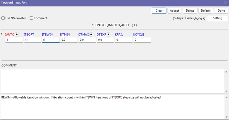
- Here the Optimal iteration value is given as 11 and the allowable iteration value is given as 5 which means which implicit analysis the iteration count can varies from 16 to 6.
- CONTROL_IMPLICIT_GENERAL: It is used to control the switching between implict and explicit flag based on the iterations count and time taken to solve it.
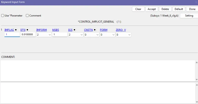
- IMFLAG= 1 Represents implicit analysis.
- Enter initial time step value in DT0
- IMPLICIT_SOLUTION: To define whether the problem is solved with linear or non linear solutions.
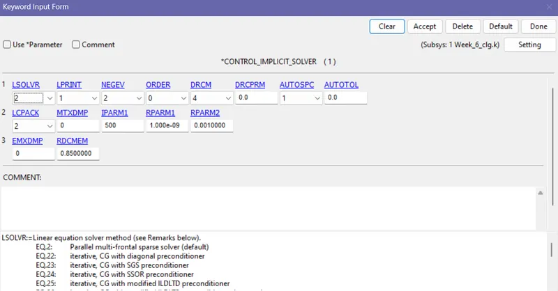
- CONTROL IMPLICIT SOLVER: This card is used to specify iterative methods and control implicit calculations.
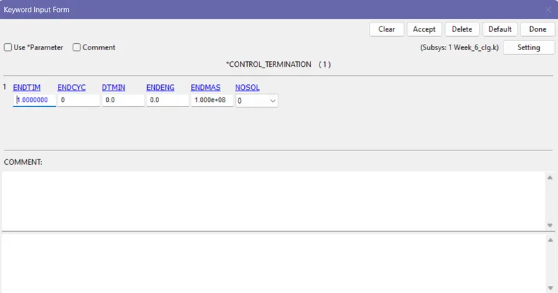
- CONTROL TERMINATION:
- End time is specified as 1 which means the box is stretched to 60mm distance within 1ms and the output is recoreded for each 0.01ms.
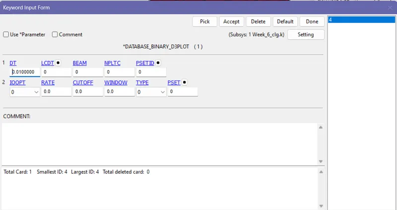
DATABASE:
- BINARY D3_PLOT : To record the animation of the completed simulation. Time step is given as 0.01ms which means it records output for each 0.01ms.
- HISTORY_SOLID: To record the results of solid elements like Element displacement, stress induced, effective plastic strain developed.
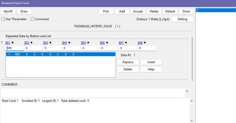
- ASCII OPTION: ELOUT and GLSTAT options are selected with time step size of 0.01ms.
OUTPUT:
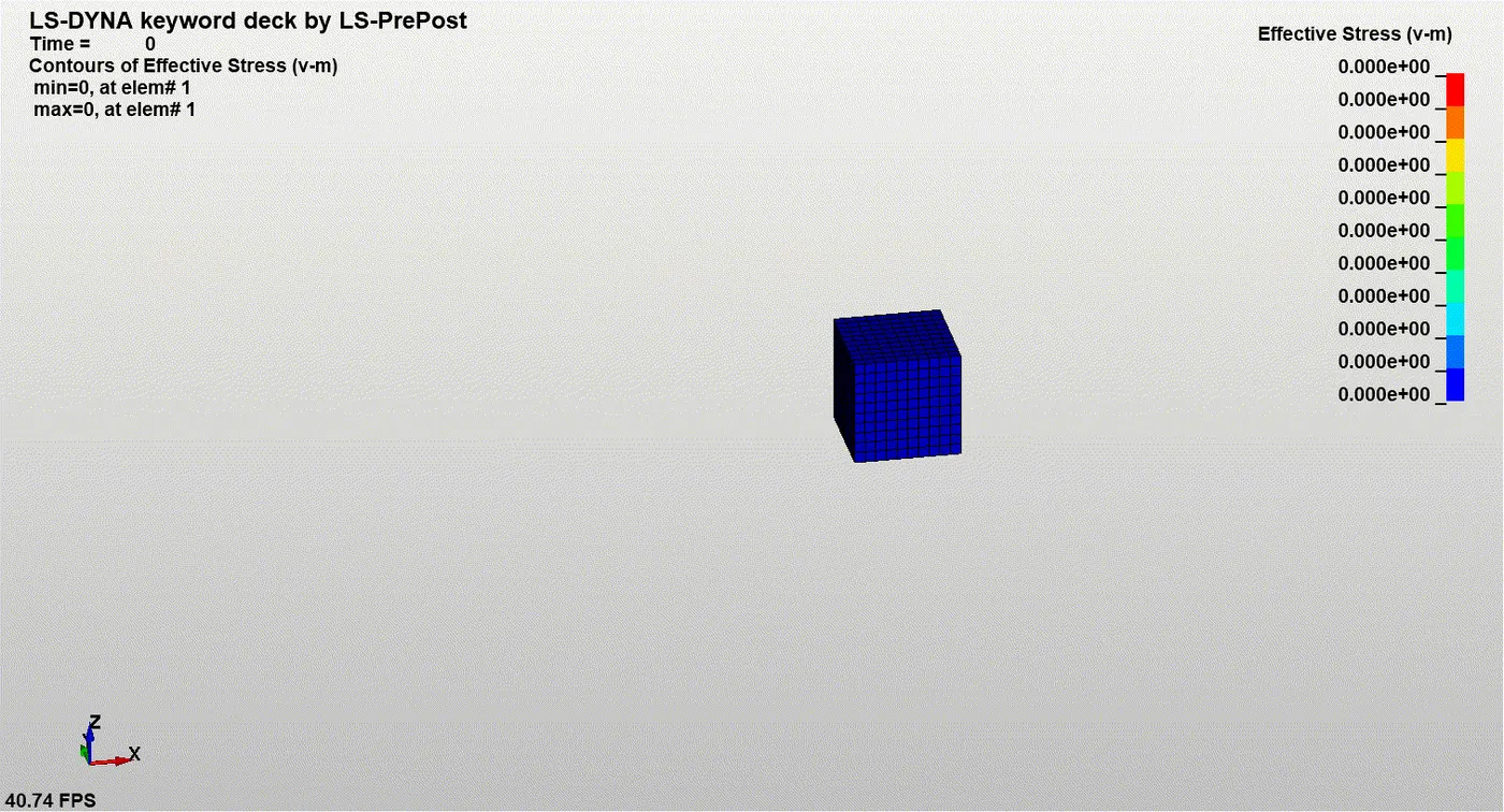
ELFORM_1:
EFFECTIVE STRESS:
EFFECTIVE PLASTIC STRAIN:
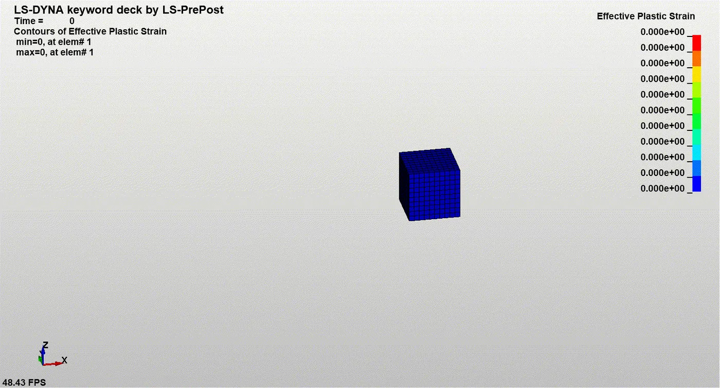
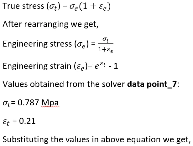
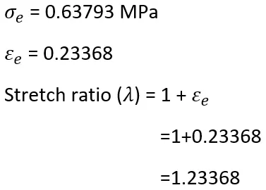
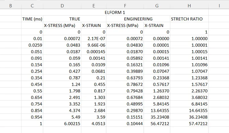
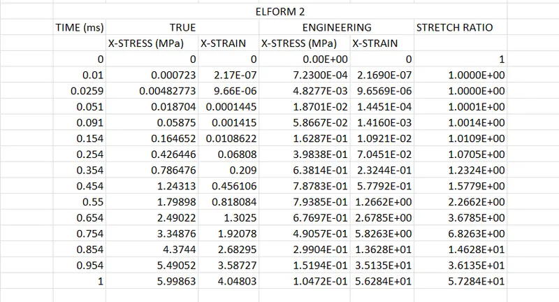
The results of effective stress and strain given by LS dyna are with respect to instantaneous area so the resuts are true stress and true strain. For determining the stretch ratio, the engineering stress and engineering strain values are needed.
CONVERTING TRUE STRESS TO ENGINEERING STRESS:
ELFORM 2:
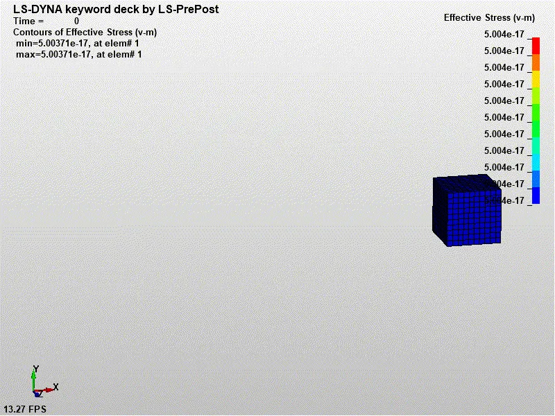
EFFECTIVE STRESS:
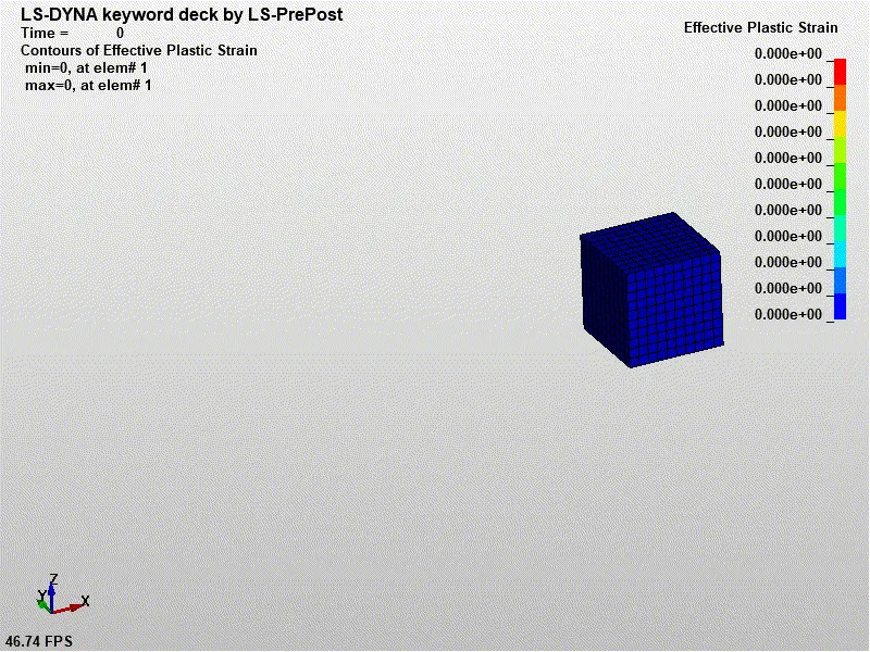
EFFECTIVE PLASITC STRAIN:
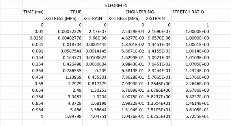
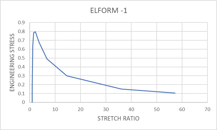
ELFORM -1:
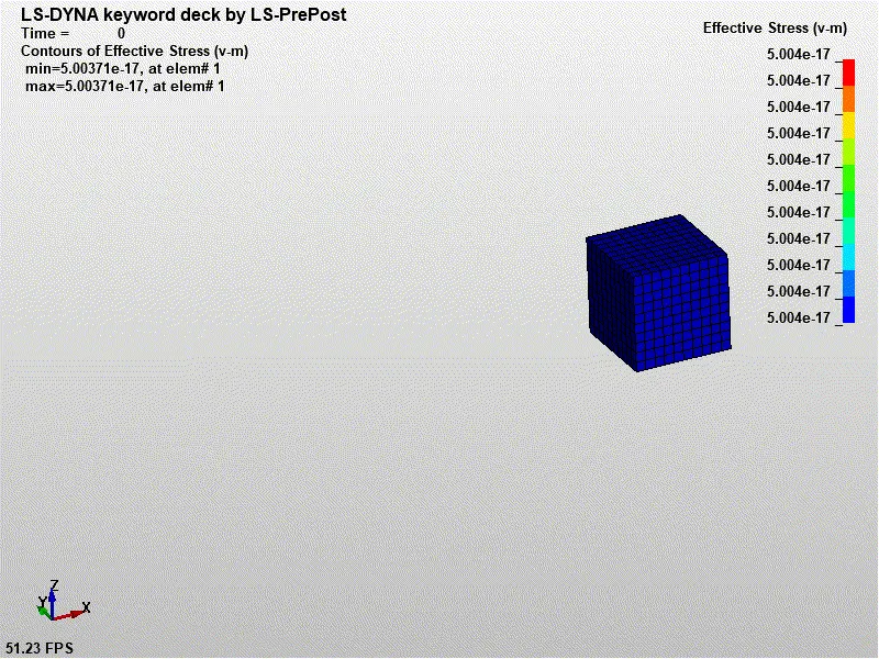
EFFECTIVE STRESS:
EFFECTIVE PLASTIC STRAIN:
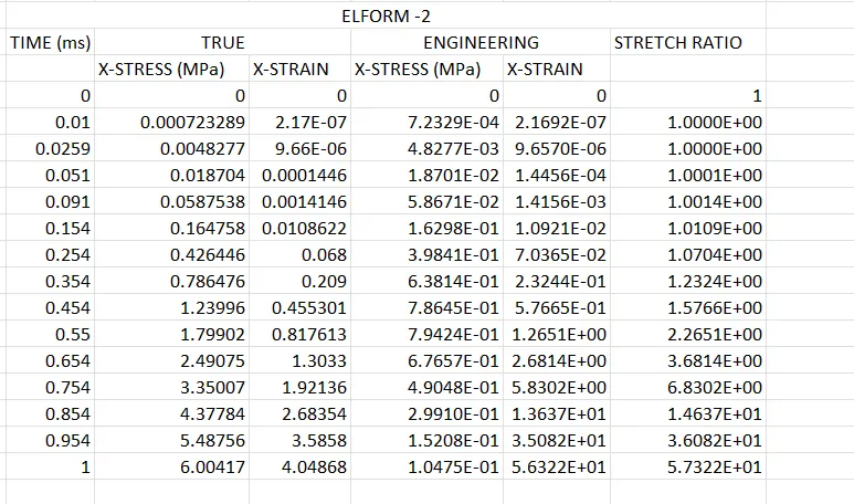
ELFORM -2:
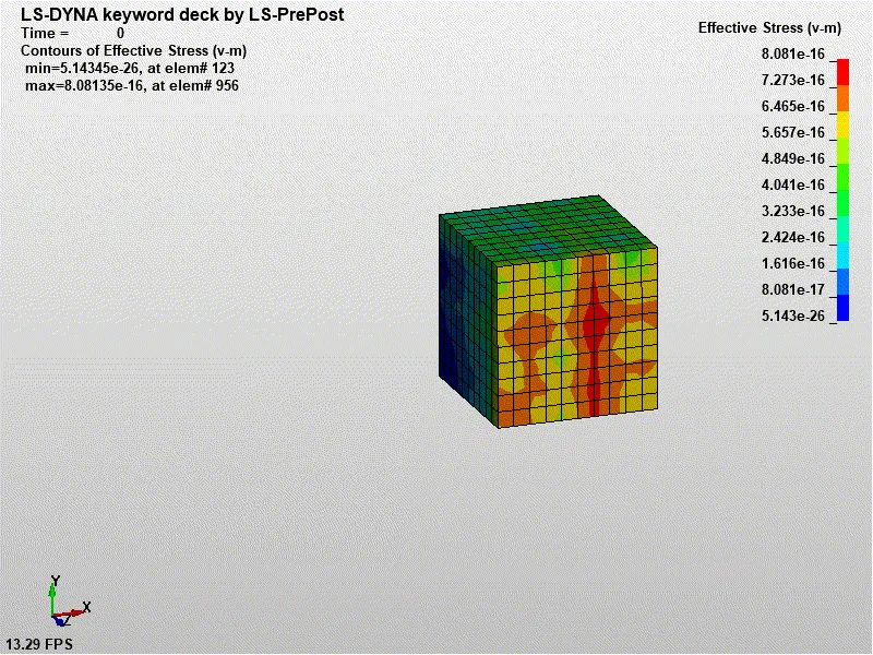
EFFECTIVE STRESS:
EFFECTIVE PLASTIC STRAIN:
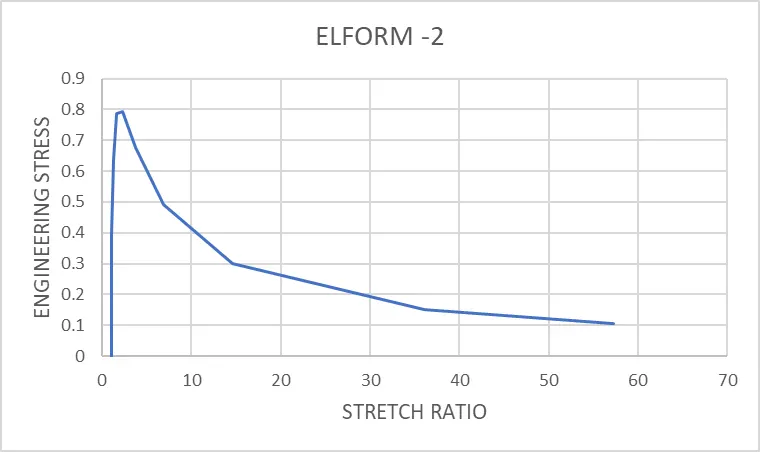
CONCLUSION:
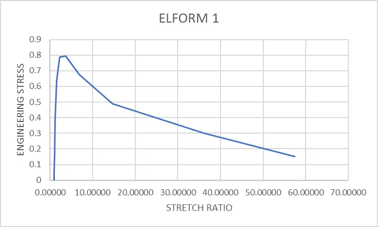
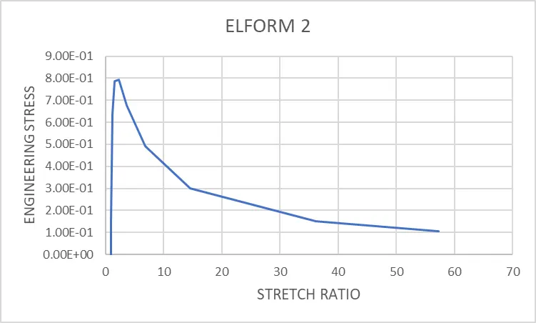
Thus the given box is applied with minimum load of 60 mm at one end and fixing the other end. By observing the stress strain data, The stress value increases steeply for stretch ratio up to 2.26. After that the stress induced decreases due to micro cracks developed and the increase in strain rate is observed. By changing the ELFORM values for the solid section a slight variation is observed. For ELFORM 1 we get stretch ratio of 57.47212, for ELFORM 2 we get 57.284, for ELFORM -1 we get 57.255, for ELFORM -2 we get 57.322