Week-6 Calculate the Stretch Ratio by comparing the ELFORM (-2,-1,1,2) with Ogden_Material Model.
Aim: Calculate the stretch ratio of a cubic block subjected to tension, used with ELFORM (-1, -2,1,2) using Ogden Material Model in LS-DYNA, and compare the uniaxial plot of stress vs stretch ratio plot among each case.
Problem Statement: To compare the results, obtain from the simulation of solid block using ELFORM -2, -1, 2, 1 The Solid Block Parameter as given below
- To create a solid block of dimension 10mm*10mm*10mm with 10 elements for each direction.
- To attach the given material model Ogden_Material.k extension file which is the representative material for this problem.
- Use appropriate boundary condition to simulate the Tensile behavior of the model and compare the results having different element formulation.
- To choose a type of solver implicit or explicit and justify the chosen solver.
- To create an excel sheet with proper conversion and calculation of stress/strain and stretch ratio for all the ELFORM.
Note: The unit of μ in the material definition is in Mpa and α is dimensionless quantity, the unit system we follow here is g mm ms
Theory:
Engineering Strain and True Strain:
Engineering strain is defined as ratio of total deformation to the initial dimension of the material in which the force is applied. The engineering normal strain or nominal strain of a material line element or fiber axially loaded is expressed as Change in length ∆l per unit original length l of the line element or fiber.
The normal strain is positive if the material fiber are stretched and negative if they are compressed
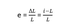
Where e is the normal engineering strain and L is the original length of the body and l is the final length of the body. Measured of strains are also expressed in terms of parts per million or micro-strains.
The logarithmic strain is the true strain, which is defined as
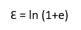
Where Ɛ is the true strain and e is the engineering strain. The logarithmic strain which is nothing but true strain provides correct measure of the final strain when deformation take place in series of increments, taking into account the influence of strain path.
Stretch ratio:
Stretch ratio is a measure used for highly extensible material such as rubber, of normal component of strain subjected to tension, and is defined as ratio of deformed length to the original length of the material body.
The stretch ratio is used in the analysis of material that exhibit large deformations, such as elastomers, which can sustain stretch ratio of 3 to 4 before fail. Whereas traditional engineering material will fail at lower stretch ratios
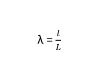
and relation between stretch ratio and engineering strain is given as
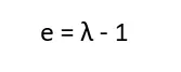
This equation implies that the normal strain is 0 when stretch is equal to unity.
Procedure:
- Import the Material Keyword file (Ogden_Material,k) which is basically a hyper-elastic material, this file only contain the material keyword only, and we proceed with this file.
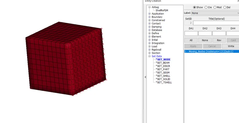
- Next step is to create the block, for that go Mesh option >> Shape Mesher >> Solid box and define the vx, vy, vz as 10mm to create the Solid box or cube of 10mm*10mm*10mm, and block is created with 10 element each in global direction.
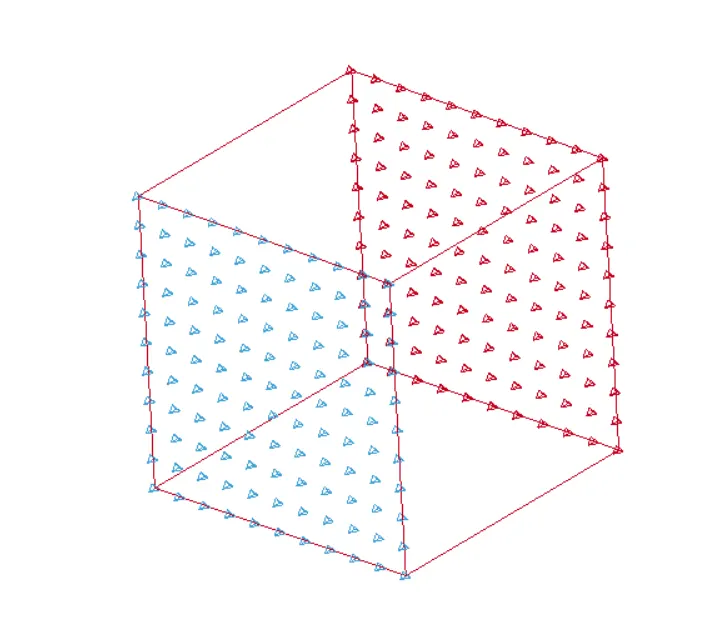
- After that we need to create a node set for defining the proper boundary condition, we created two nodes set one for the spc constraint and second is for the prescribed motion.
 l
l
Defining Node Set for Boundary Condition
- After defining node set, the next step is to create the spc on one side and fix the translational X DOF, so that it can’t move during stretching of model.
- Now define the Prescribe motion set for the node, select the node set id and define the proper displacement curve.
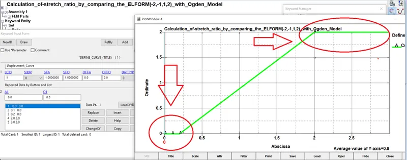
Defining a Displacement curve
Here we are applied displacement with respect to time, as per recommendation we don’t apply abrupt displacement, which is not recommendable, so we give time for displacement to be applied in steps, also if we solve this problem using implicit analysis, it is recommended to use displacement loading rather than Force because of more stable behavior.
Material Setup:
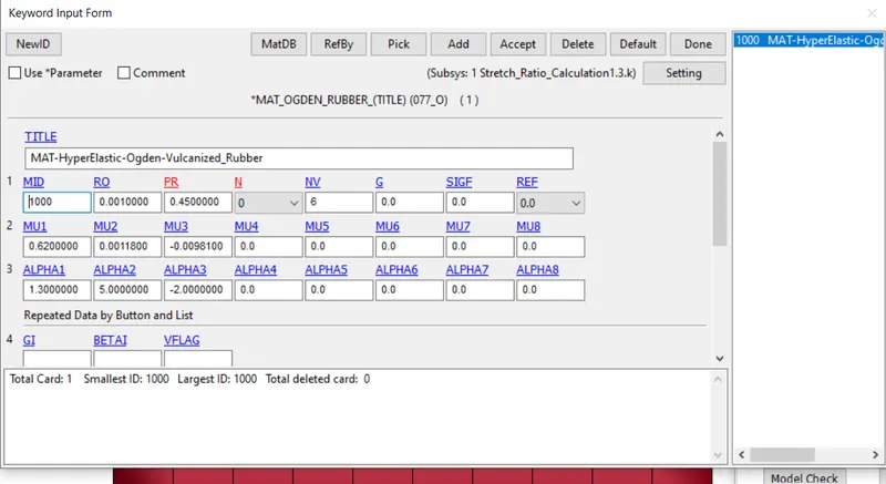
The block is modeled with *MAT_077 Ogden material model, which is a hyper-elastic material model used to describe the non-linear stress strain behavior of complex material such as polymers, rubber and biological tissues.
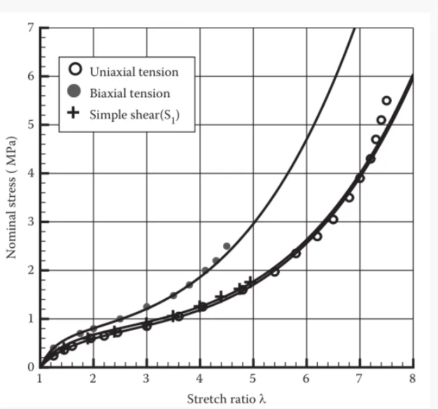
The Ogden material is referenced to the block using part option, the strain energy function in the Ogden material is written with components stretch ratio λ, shear modulus μ and constant α
The following fig displays the details of various property of Ogden model rubber material
Analysis method:
In order to run the tensile behavior of the block we use implicit analysis scheme.
LS-Dyna employs both Implicit and Explicit analyses methods to solve static and dynamic problems, that differ in the approach to time increment.
In implicit analysis each time increment has to converge, but we can set a long time increment, Explicit analysis on the other hand doesn’t need to converge at each time step. Implicit analysis work in a way that at each time increment global equilibrium is established, this basically happens in iterative methods, generally implicit analysis method is used for its accuracy in results and can be applied for longer duration problems.
- For implicit analysis we have to define some necessary Keyword, the most important kword is *CONTROL_IMPLICIT_GENERAL which is necessary for the problem to solve by implicit scheme, because LS-Dyna is by default solve all the things by explicit approach, so we need to define the control implicit general in order to activate the implicit solver.
*CONTROL_IMPLICIT_GENERAL This keyword make it sure that the analysis will start in an implicit manner since the default analysis made for Ls-Dyna is explicit, we can set some initial time step.
There are also some necessary but not essential option for implicit analysis are
- *CONTROL_IMPLICIT_AUTO: Strategy to change time-step, due to unconditionally stable in implicit we can change the time step or load step depending upon how your solver will going to solve the problem.
- *CONTROL_IMPLICIT_SOLUTION: This keyword is for non-linear solver, Numerical method and convergence tolerance section along with output diagnostics.
- *CONTROL_IMPLICIT_SOLVER: This keyword is for linear solver parameter, the solver that perform matrix inversion.
- *CONTROL_IMPLICIT_DYNAMICS: Activates dynamic analysis and define time integration constraints.
- *CONTROL_IMPLICIT_EIGENVALUE: Activate implicit eigen value analysis
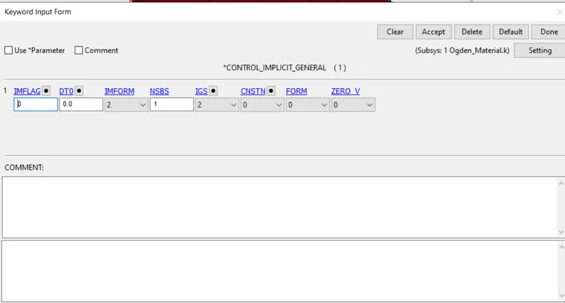
*CONTROL_IMPLICIT_GENERAL is defined
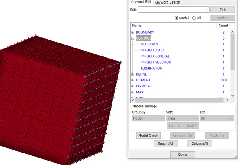
Defining rest of parameters for Implicit
- To run the simulation properly we need to create the control card, without creating control card simulation will not start, and the most important one is termination card, which will define the running time for the simulation. Control Hourglass energy, Accuracy, Energy.
- Now our initial setup is done, now we need to define the output, for that go to Keyword >> binary d3 plot, this is the main animation file also we need to request the ASCII output as well and in it contains the result of GLSTAT, MATSUM, RCFORC, etc.
Note: Here we need to add *DATBASE_EXTEND_BINARY card and activate STRFLAG to get the strain data.
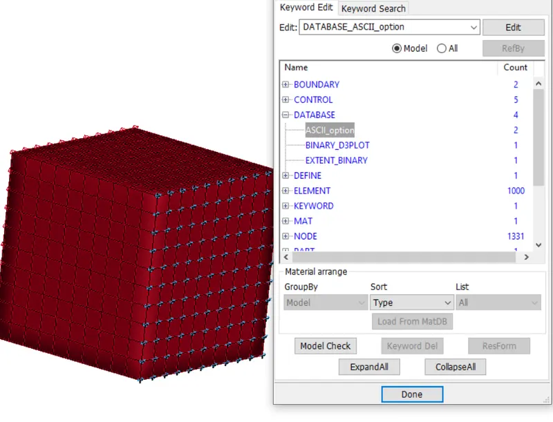
Defining ASCII and Binary output
Section Setup:
The FE model of block is modelled with solid section in LS-DYNA. Element formulation deals with mathematics and assumption that derive the development of the displacements for different finite element types. Insights gained from displacement of the element help determine the strain, stress and nodal forces of that type of the element.
Element formulation such as ELFORM -2,-1,1,2 are used in this case to validate the results.
ELFORM-2: Fully integrated S/R solid element intended for elements with poor aspect ratio, accurate formulation
ELFORM-1: Fully integrated S/R solid intended for elements with poor aspect ratio, efficient formulation.
ELFORM1: Constant stress solid element
ELFORM2: Fully integrated S/R solid.
The solid section is referenced to the block using part option.
Model Checking and Solving the setup
One of the most important pre-processing task is to ensure the validity of CAE model before submitting it to the solver for solution.
A good and rich suite of check reduces engineering errors, increases confidence in the simulation results and minimize the duration of simulation cycle by eliminating multiple back and forth from the solver to pre-processor
- Now our deck setup is completely, now one thing left is only to check the file, whether there is any error present or not, if present then remove those error before giving them to solve in solver.
- After that we can save the file, but before that one important thing is to check the error before solving the file, if error is present then file is not able to solved by the solver, so make sure to solve all the error and after that save the file.
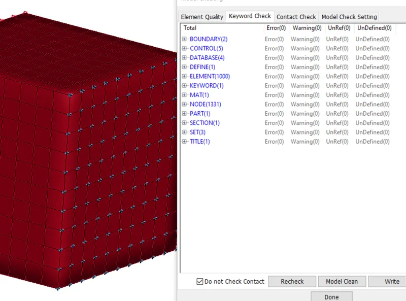
No keyword error and warning
- After saving the file, the next step is to open the file in Notepad and edit or give the title and add Keyword ID, because it is a general practice and it is recommended, so that file and their result will not mismatch, otherwise if we don’t follow this then there are more chances of mismatch of results, if you do slightly change in the condition and you don’t know which result or d3 plot belong to which, so it is recommended to give them title and Keyword id so that, our result should coming up with proper name.
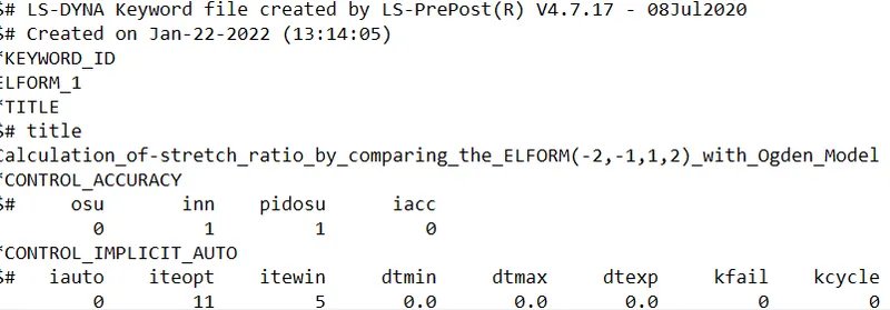
Giving a proper Title and keyword id to file
- Now our file is ready for solving. To solve the file, open the Ls-Dyna Run and import the file here and then run the file for solving, it will show you how much time it take to solve the file, after solving the file it will gives you result in the form of the input we define like main animation file like Binary d3 plot
- Now we got lot of files in the form of result, but our main file is the d3 plot which is a binary file, we can open it in any editor, but this file is not readable, but we have ASCII file which we can open it in notepad, but it is readable, so we again open the LS-Dyna and then open the dyna binary file in it.
Post processing results:
The requested outputs for d3plots, history and ASCII option are now ready to view in Ls-Prepost for post processing
Animation of the Simulation
- Uniaxial Stress vs Stretch ratio plots:
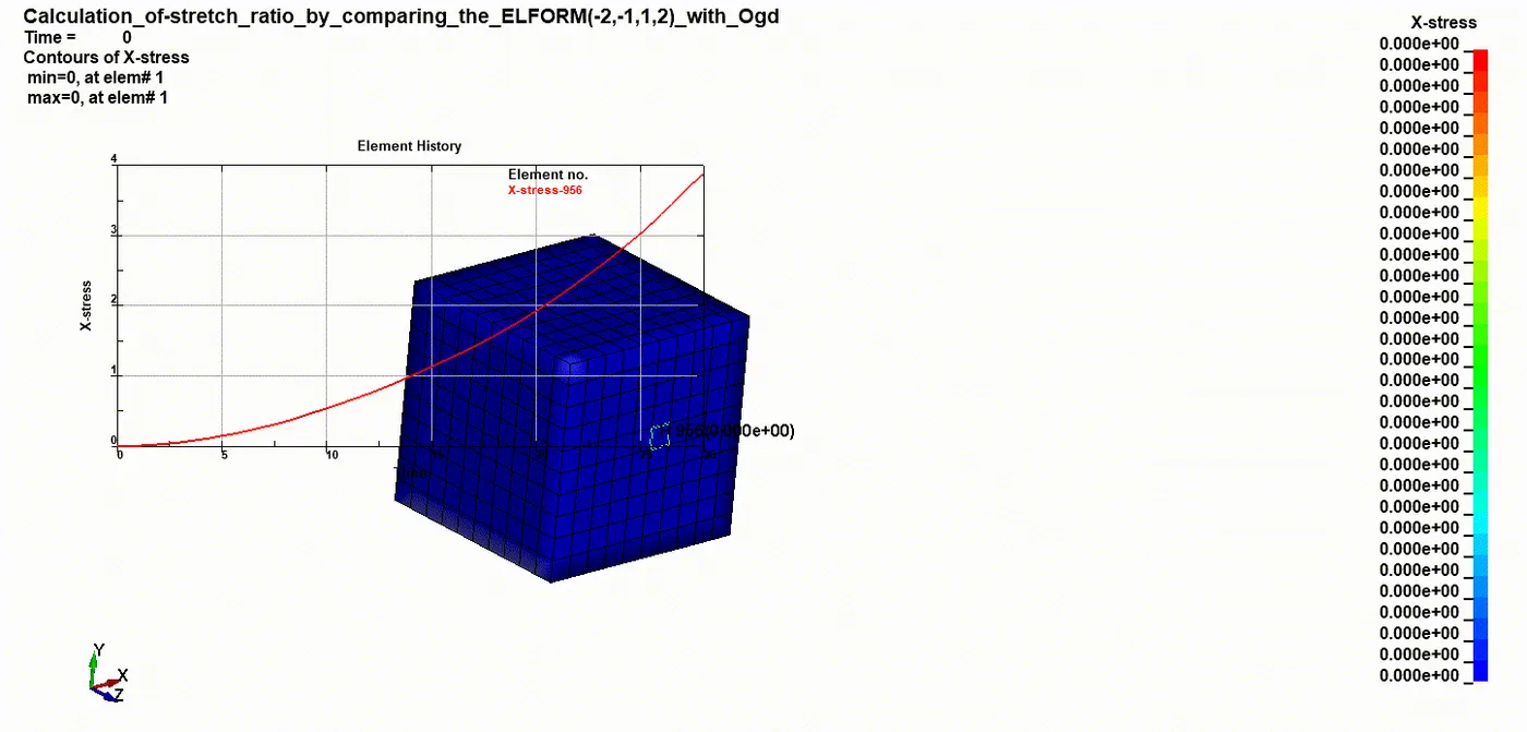
Since the block is subjected to tension only in global X direction, a uniaxial stress vs stretch ratio plot, for all element formulation cases is sufficient to validate the result.
The stress and strain in the fringe component of LS-Dyna postprocessing tool are actually a True stress and True strain value, therefore suitable calculation are need to performed to convert it into Engineering stress and strain.
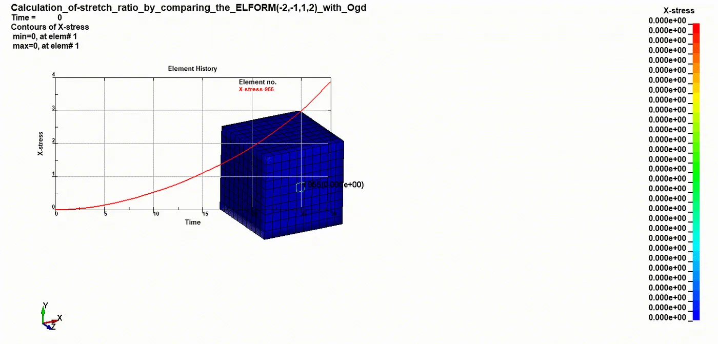
ELFORM 1
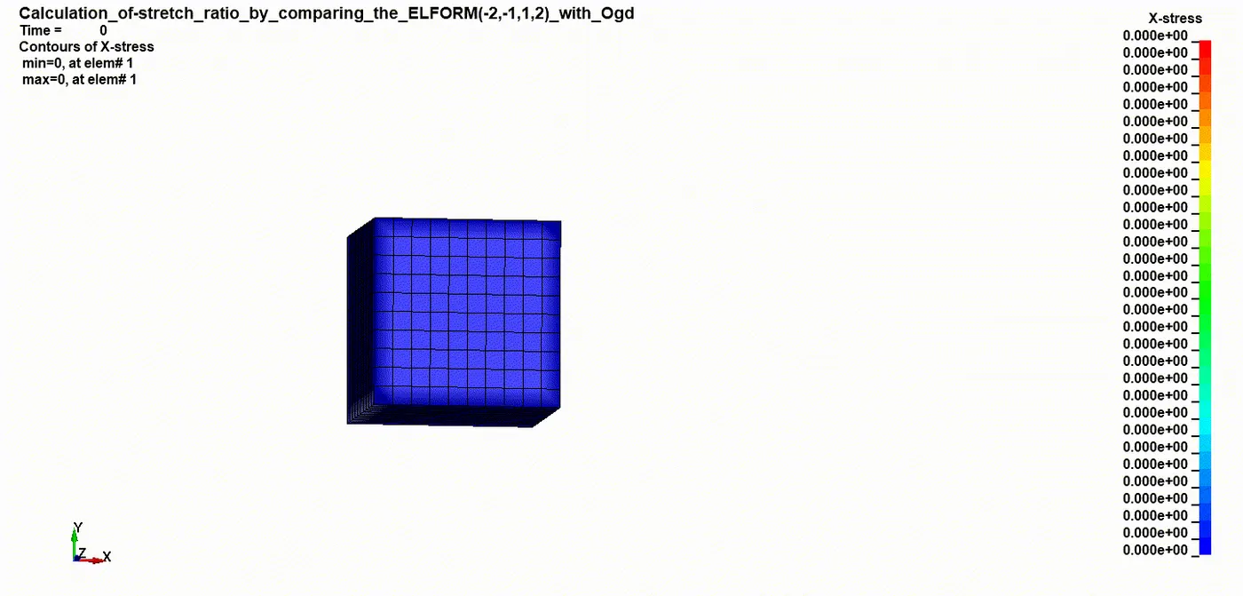
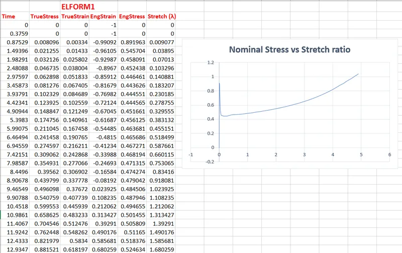
X-Stress vs Stretch
ELFORM 2:
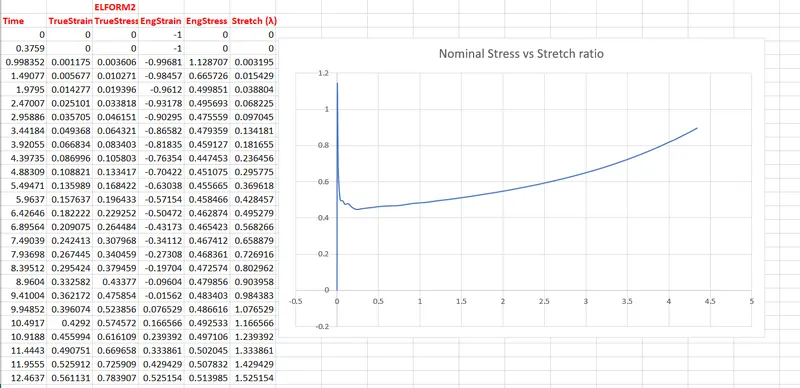
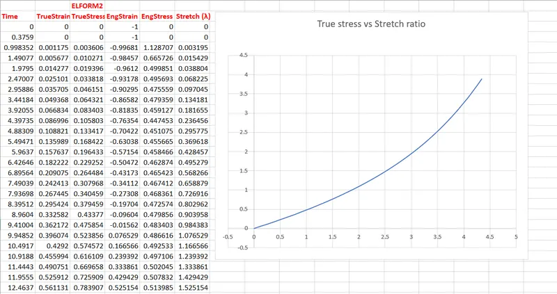
True Stress vs Stretch
ELFORM -1:
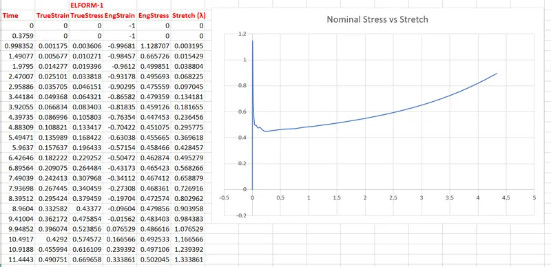
ELFORM -2:
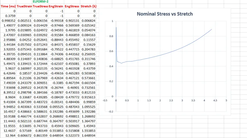
Comparative Inference: From the plot obtained from the simulation data, it is found that maximal uniaxial stress in X-direction of tension is typically same in all the solid element formulation cases. but we get higher value of stress for the ELFORM 1 (Constant Stress solid element) at the stretch value of approx 4.4
There might be little variation in the cases this is due to the use of different element formulation for Solid elements of Block.
Conclusion: Thus, a tensile loading simulation is performed on a cubic block using Hyper-elastic ogden model material like vulcanized rubber. Various solid element formulation had been applied in each cases accordingly and the post processing results are validated.
Implicit scheme approach is used to solve the problem in order to obtain an efficient formulation of results. Since the data obtain from the fringe component of LS-Dyna are in terms of True Stress and Strain, they are converted into Engineering stress and strain accordingly with suitable conditions.
The Plot of Nominal stress vs Stretch ratio plots for all element formulation cases has been drawn and data are concluded.