Week-6 Calculate the Stretch Ratio by comparing the ELFORM (-2,-1,1,2) with Ogden_Material Model.
Objective of the challenge: To calculate the stretch Ratio by comparing the different ELFORM types (-2,-1,1,2) with the material as Ogden Material Model
Unit system used: g-mm-ms
Introduction:
An Ogden model is a hyperelastic material model, that can be used for predicting the nonlinear stress-strain behaviour of the material such as rubber or polymer. The Ogden model has been frequently used for the analysis of rubber components like O-ring and seal. Even though the Ogden model is a hyperelastic material model, its strain energy density function is expressed by the pricipla stretch ratio.
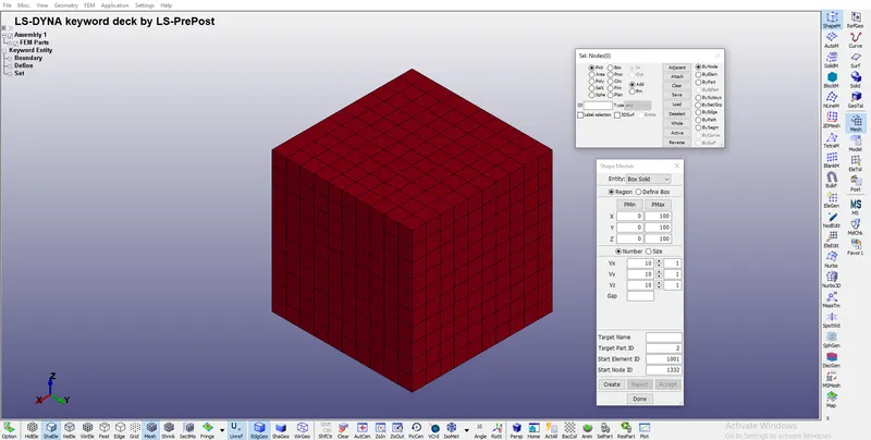
To start with the simulation we create a block of 10mmx10mmx10mm dimension with 10 elements for each direction, which results in having 1000 solid elements connected by 1331 nodes.
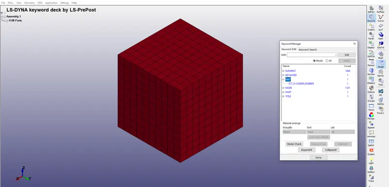
Now we have important keywords like MAT, PART, ELEMENT and NODE in the keyword Manager
1) *SECTION
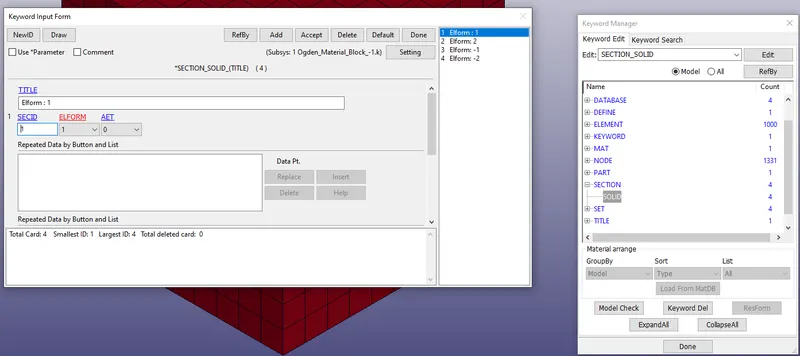
In the Section keyword, we create 4 different sections using *SECTION_SOLID having different Elform types as -2,-1,1 and 2 as given in the objective where Elform
=-2: fully integrated S/R solid intended for elements with poor aspect ratio, accurate formulation.
=-1: fully integrated S/R solid intended for elements with poor aspect ratio, efficient formulation.
= 1: constant stress solid element (default input in *section_solid)
= 2: fully integrated S/R solid
2) *MAT
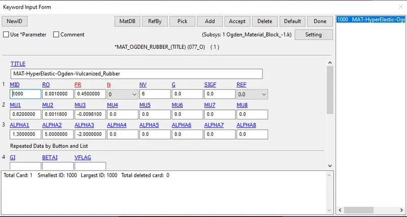
The material for the block is already given in the challenge which is MAT_077- OGDEN_RUBBER along with the paramteres assigned it to it. We use the same card for adding material to the block.
3) *PART
Using *PART keyword we link the section and material used for definign the block
4) *BOUNDARY
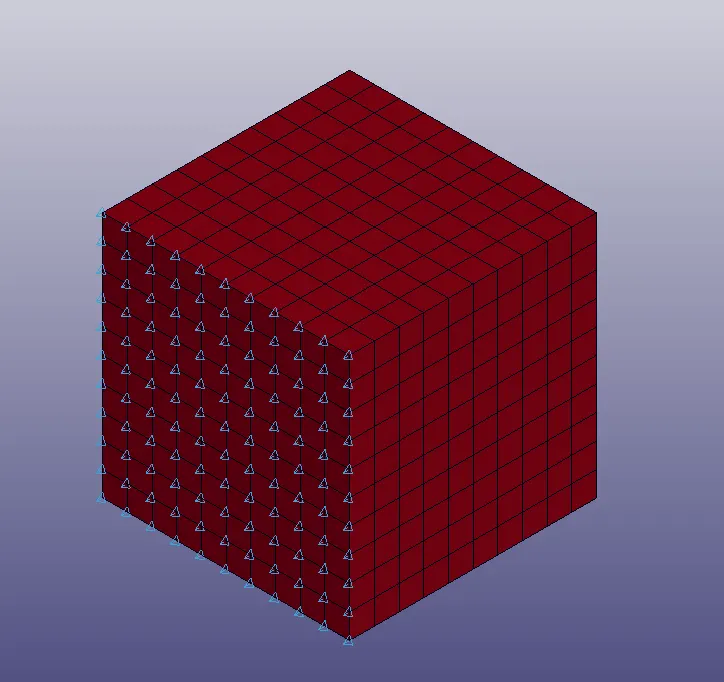
Using appropriate boundary conditions to simulate tensile behavior for the model, we fix one surface of the block and the opposite surface of the fix end is given a linearly varying prescribed motion of 10mm
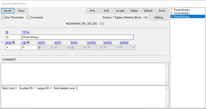
- SPC_SET
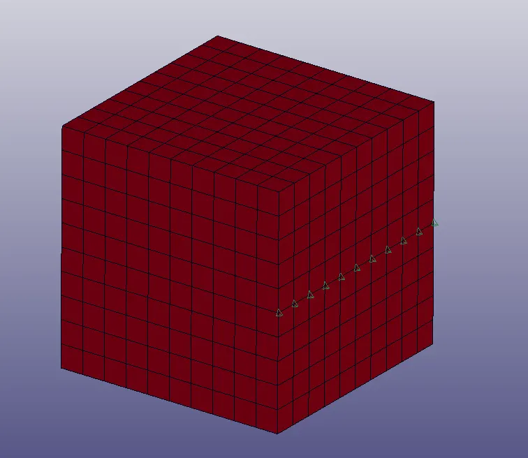
For SPC_SET, we create different sets of nodes to be constrained along different directions of the global coordinate system.
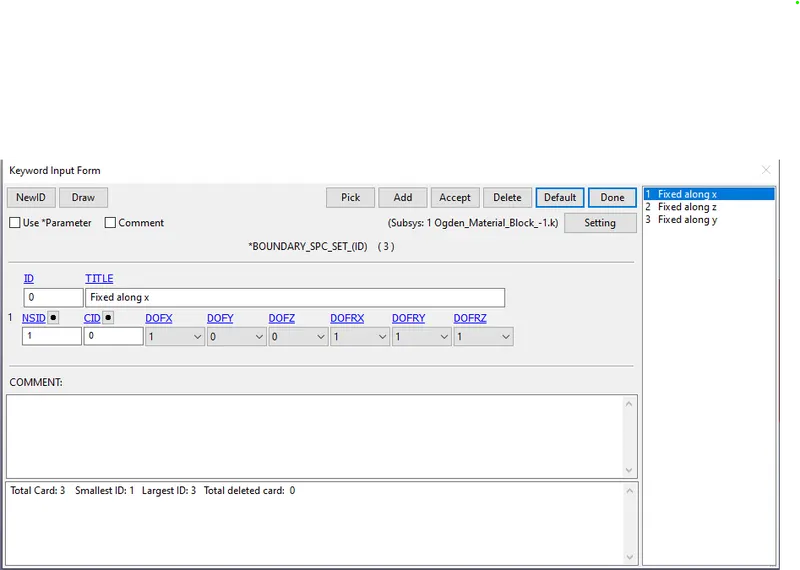
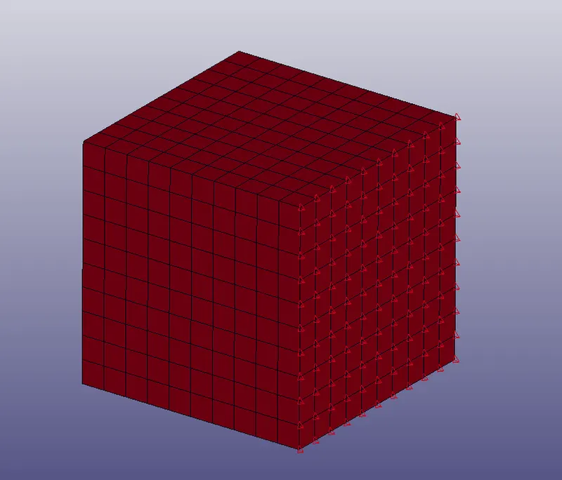
a) The set along x direction : In this case the whole face of the block is constrained only in x translation and rotational constarints along all three axis
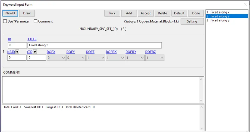
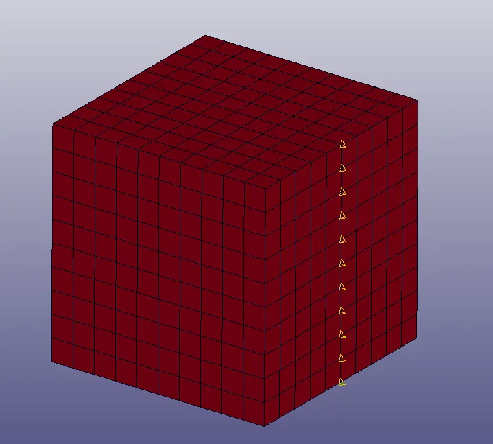
b) The set along y and z direction: In this case the centre set of the face of the fixed nodes ( in x-axis) are fixed in the y direction and z direction of translation, so as to incorporate the effects of Poisson ratio of the material
- PRESCRIBED_MOTION_SET
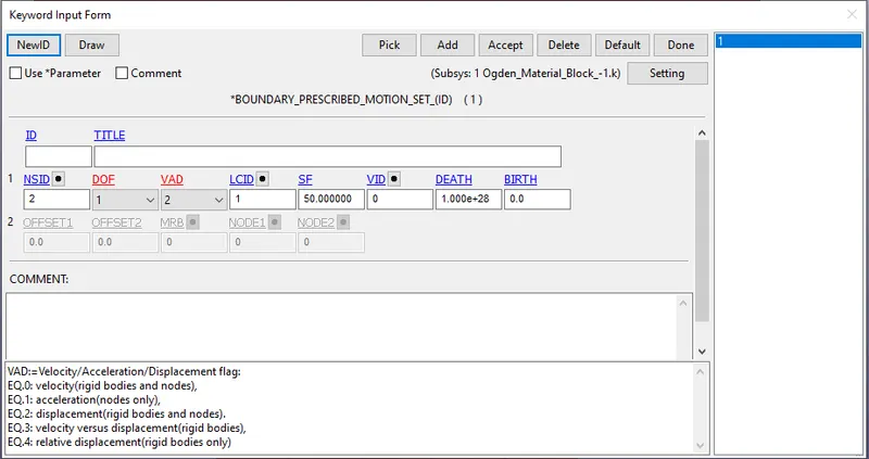
For prescribed motion set, the degree of freedom is chosen to be 1 which in the x-direction translation where the set of nodes move with fixed displacement which is given by VAD flag equal to 2. The motion of these nodesets is determined by defined by the load curve ID (LCID) using the *DEFINE_CURVE in the keyword manager.
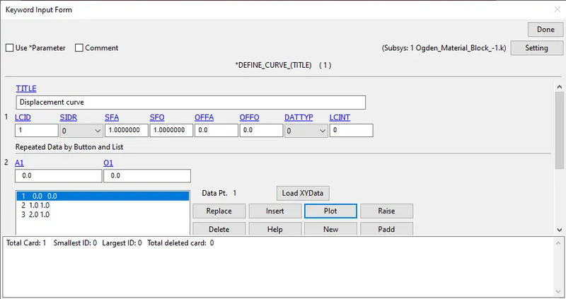
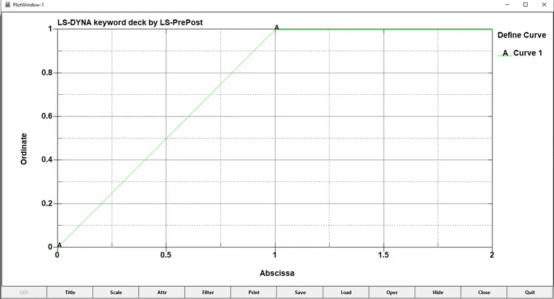
The value of the displacement is chosen as follows:
The load to be applied to the moving face to attain the stretch ratio is calculated where Stretch ratio `lambda` is defined as the ratio between the final length `L` and the initial length `L_0` of a component. In other words, it can alos be termed equal to (1 + engineering strain)
Stretch ratio, `lambda=1+epsilon_0` where
`epsilon_0=frac{L}{L_0}`
In the given problem, we need to analyze till stretch ratio of 5 and length of the block is taken as `L=10mm`
`5=1+frac{deltaL}{10}`
`Rightarrow deltaL = 40mm`
For the safer side the displacement is chosen to be 50mm. A curve is defined with displacement of 50mm.
As the material we use here is an Ogden Material which is a hyperelatic material model that can be used for predicting the non-linear stress strain behaviour of material such as rubber or polymer. In the Implicit Method, displacement loading is recommended rather than force load to achieve a more stable load. So this problem is solved using Implicit method.
5) *CONTROL
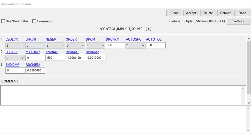
As LS-Dyna is a general purpose explicit software, there are some cards which can be used to switch to implicit solving methodology.
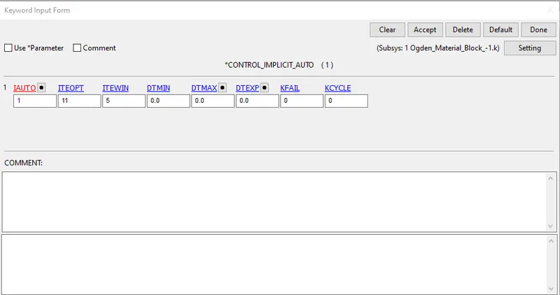
*CONTROL_IMPLICIT_AUTO:
Define parameters for automatic time step control during implicit analysis using parameter IAUTO=1
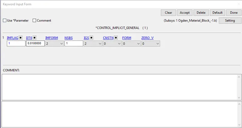
*CONTROL_IMPLICIT_GENERAL:
Activate implicit analysis and define associated control parameters. This keyword is required for all implicit analysis. The parameter IMFLAG is responsible for Implicit/Explicit switching flag which is set to 1 for Implicit analysis. The Initial time step size, `DT_0` is set as 0.01 for implicit analysis.
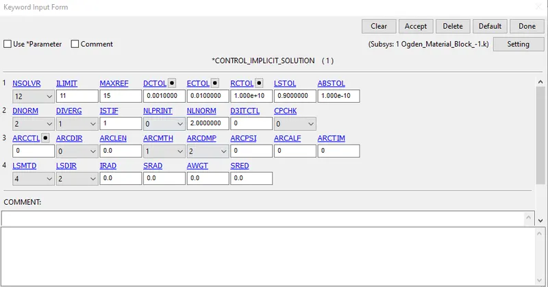
*CONTROL_IMPLICIT_SOLUTION: These optional cards apply to implicit calculations. These cards are used to specify whether a linear or nonlinear solution is desired.
*CONTROL_IMPLICIT_SOLVER:
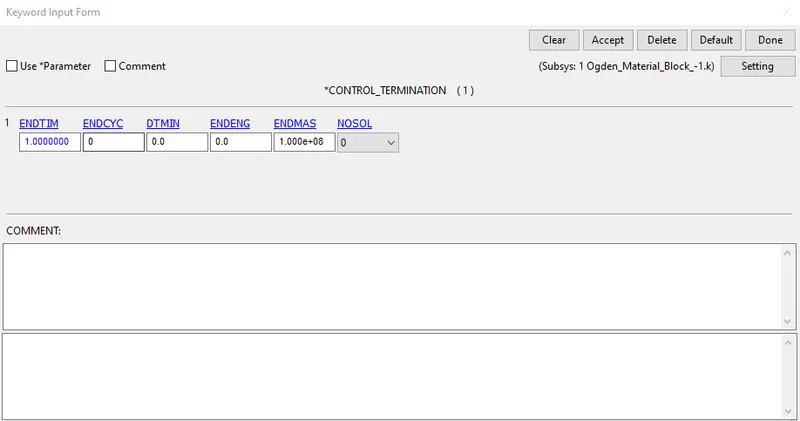
*CONTROL_TERMINATION: The termination of this simulation is set as 1ms
6) *DATABASE
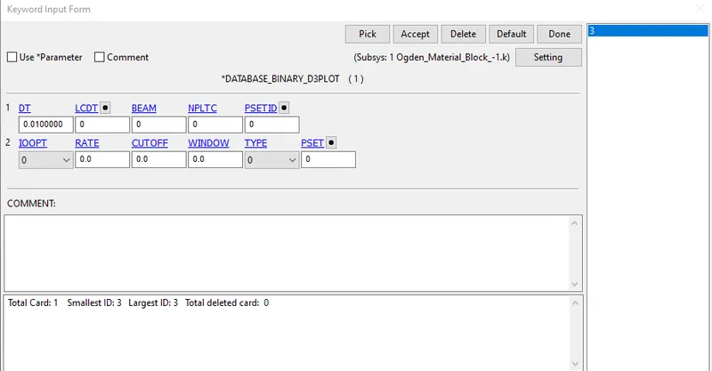
- BINARY_D3PLOT
The animation file for the final simulation is read for every 0.01ms
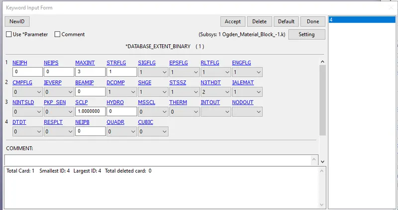
- *Database_Extend_Binary
Adding this option to activate the STRFLG to 1 to get the strain data.
OUTPUT
The stresses and strains obtained from the postprocessing fringe components are essentially the output true stress and true strain
We need to convert to Engineering stress in order to plot the graph for stretch ratio and stress
The following are the relations used for the calculation:
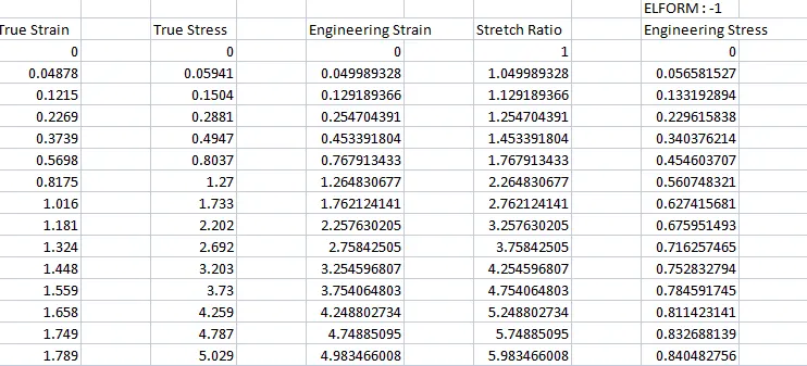
True stress, `sigma_t=sigma_e (1+epsilon_e)`
True strain, `epsilon_t=ln(1+epsilon_e)`
Stretch ratio, `lambda=1+epsilon_e`
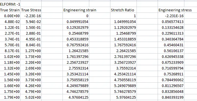
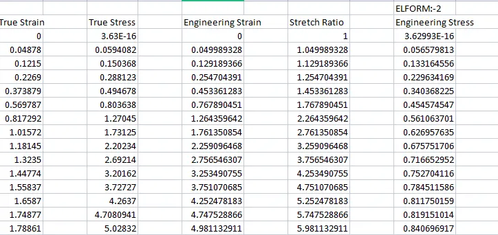
Using the above relations we generate the excel sheet as shown below:
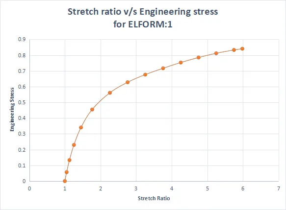
Data sheet and Stress vs Stretch data for Elform type 1
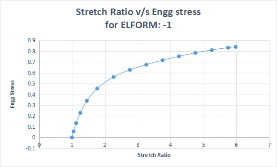
Data sheet and Stress vs Stretch data for Elform type -1
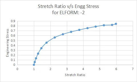
Data sheet and Stress vs Stretch data for Elform type -2
Data sheet and Stress vs Stretch data for Elform type 2
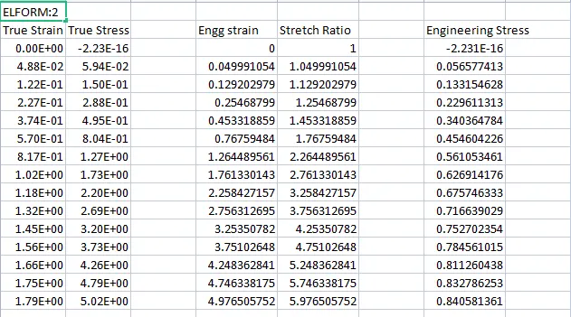
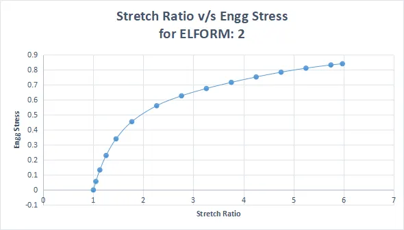
From the results it was found that the hyperelastic material exhibits stretch ratio of 5.9 at 0.85MPa.
Conclusion:
- The uniaxial test was performed on the cubical block with solid elements modelling with Ogden Rubber material model. The analysis was performed using ELFORM type -2,-2,1,2
- The true stress and true strain was found out from the results and available relations were used to calculate the engineering stress and stretch ratio. Finally the plot of stretch ratio and engineering stress was generated.
- Implicit methodology was used to solve the problem as the displacement imposed was low similar to that of a quasistatic modelling over a hyperelastic non-linear material.